Using GUIs To Control Two Robots — Update: Multi-Platform GUIs
By Edgardo Peregrino View In Digital Edition
In my last article, I showed how to control two robots at once using guizero, gpiozero, and pigpio. Since then, I have done more tests and found ways to make this run outside of a Raspberry Pi. I’ll explore those options in this update, as well as provide an introduction to PWM (pulse-width modulation) and how to use the L298N to control the speed of motors. This update is necessary to show users how to not be restricted to the confines of a Raspberry Pi and also to make it more portable than it already is.
Catching Up
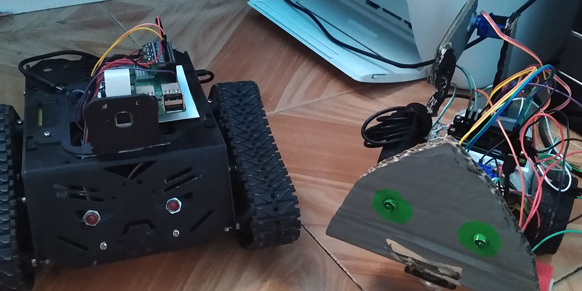
Before proceeding further, let me get you up-to-speed on my project. The project is based on the Python module guizero and also uses gpiozero and pigpio to control the robots remotely. Figure 1 shows both robots that I used for the last article.
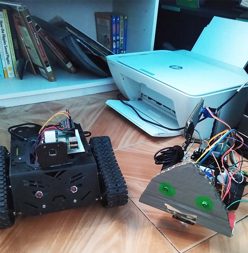
Figure 1: My robots, Torvalds (left) and Linus (right).
They’ll be the focus for this article as well.
Figure 2 shows the main GUI that was used to control both robots.
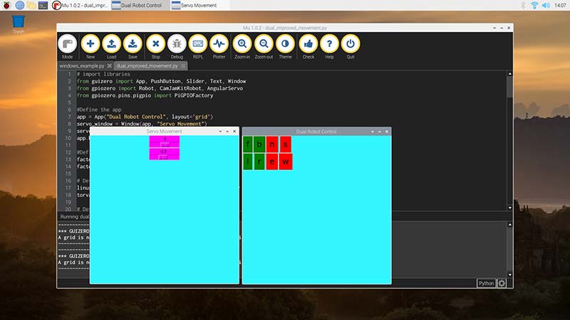
Figure 2: Screenshot of dual_improved_movement.py being run on Mu.
I also added an optional GUI to record video from a Pi camera, as well as an updated optional GUI that uses software speed control.
Here’s the list of items again that I used for both robots so you can catch up:
Linus
- Generic robot car chassis.
- CamJam Edukit 3, motors, and wheels.
- Jumper wires.
- L298N motor controller.
- CamJam Edukit 3 6V battery pack.
- Cardboard (for the face and servo arm).
- Gray and green paint (for the face and the servo arm).
- Two PC style power LED connector cables (for the eyes).
- Raspberry Pi Zero W.
- Raspberry Pi Zero W case.
- Plasticard (to mount the Pi and L298N).
- Two 9g servos.
- CamJam Edukit 3 breadboard (for the servos to avoid using both 5V rails).
- Standoffs for the L298N.
- 32 GB micro SD card.
- 5V 2.1A USB power bank.
- Micro USB cable with power switch.
Torvalds
- DF Robot Devastator Tank Mobile Platform.
- Two PC style HDD LED cables (for the eyes).
- LED bezels.
- Raspberry Pi 3B+.
- 32 GB micro SD card.
- Cam Jam Edukit 3 motor hat.
- Plasticard and standoffs for the Pi 3B+ and the base of the robot.
- Six AA batteries (for the motor).
- Raspberry Pi camera.
- 3D printed camera mount.
- 5V 3A USB power bank (to power the Pi).
- Jumper wires for the LED eyes.
Android/iOS Control
In order to use this project on an Android or iOS, I used a modified version of the project and renamed it to dual_robot_mobile.py. All I did was a slight modification. I removed the pin factory from my robot Torvalds, so now the code will run from a phone, tablet, or hybrid tablet/laptop.
To do this, I downloaded VNC Viewer on Android which is available on iOS as well. I also enabled VNC from the Raspberry Pi Configuration Menu. I then obtained the IP address from Torvalds and logged in with my username Pi and a password I changed from the default to avoid security issues.
It booted to a desktop and then I loaded the file by using Mu. Also, I accessed my other robot Linus using SSH and then made sure to enable pigpio by launching the sudo pigpiod command. This runs the pigpio daemon. Once that was set up, I made sure the pin factories were correct in the code and then I ran it. After that, I used the touch screen to press the buttons and move the sliders for the servo arm. Figure 3 shows a screenshot of VNC viewer on Android.
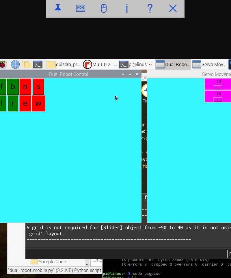
Figure 3: Screenshot of dual_improved_movement.py running on VNC Viewer in Android.
VNC Viewer Option
Aside from the Android/iOS, the dual_robot_mobile.py code can also be run on any computer that has VNC Viewer installed. Whether it’s Linux, MacOS, or Windows, make sure you have VNC Viewer installed.
Gpiozero Issues
Before proceeding further, there are some issues that need to be addressed because they continue to be a problem for users who try to run motors or a robot remotely. I ran into this problem myself.
Currently, there’s a bug in gpiozero that prevents motors and robots from running remotely. There is a workaround such as setting the PIGPIO_ADDR variable equal to the IP address of the Pi and then running the code with no reference to the pin factory. That’s fine, but in this case, we can’t do that because the code can’t run in a terminal since guizero is meant to run in an IDE (integrated development environment) such as Mu or Thonny.
So, I had to install the 1.5.2 beta which did work, but as of now the new version is known as 1.6.2. To bypass this, I had to make some changes to the code to make the project run on other desktops, laptops, and tablet/laptop hybrids.
Let’s talk about the gpiozero classes OutputDevice and PWMOutputDevice.
The gpiozero class OutputDevice is a base class that represents any output device that turns on or off according to the official documentation. This behaves similarly to the LED class, for example, where you can turn it off, on, and blink. This class will work with pigpio since it doesn’t suffer from the bug issue that a motor does. This class will be used with the L298N as well as the next class that I will discuss.
The next class — PWMOutputDevice — is a base class that represents any output device with PWM. I’ll cover this concept in the next section. The frequency of this class is set at 100 Hz which is optimal for most cases.
Also, the value of the duty cycle is between 0 and 1, similar to the speed set with the Robot and CamJamKit Robot classes. This one and the last class I mentioned will be needed to run on Linux, Mac, and Windows, and I’ll explain how PWM works with the L298N.
Intro to PWM
To begin with, pulse-width modulation is a process where the power level of an electrical signal is reduced; hence, is represented as a square wave. PWM is always between 0 and 1 unlike digital signals that are either on or off. In gpiozero, PWMLED uses PWM to control the brightness of an LED.
Similarly, RGBLED controls the brightness level of its three colors: red, blue, and green, thus creating different colors such as cyan, yellow, and orange.
The Servo class also uses PWM to control the position of its arm and AngularServo uses PWM to control the angle of the servo arm. Motor and Robot also use PWM for speed control.
In the next section, I’ll explain how the L298N and other motor controller boards and HATs use PWM.
PWM and the L298N
The L298N isn’t just used to control the motors. It’s also used to control the speed of motors. In Figure 4, the two arrows point to the enable pins which keep the motors at high speed at all times, unless software PWM is implemented.
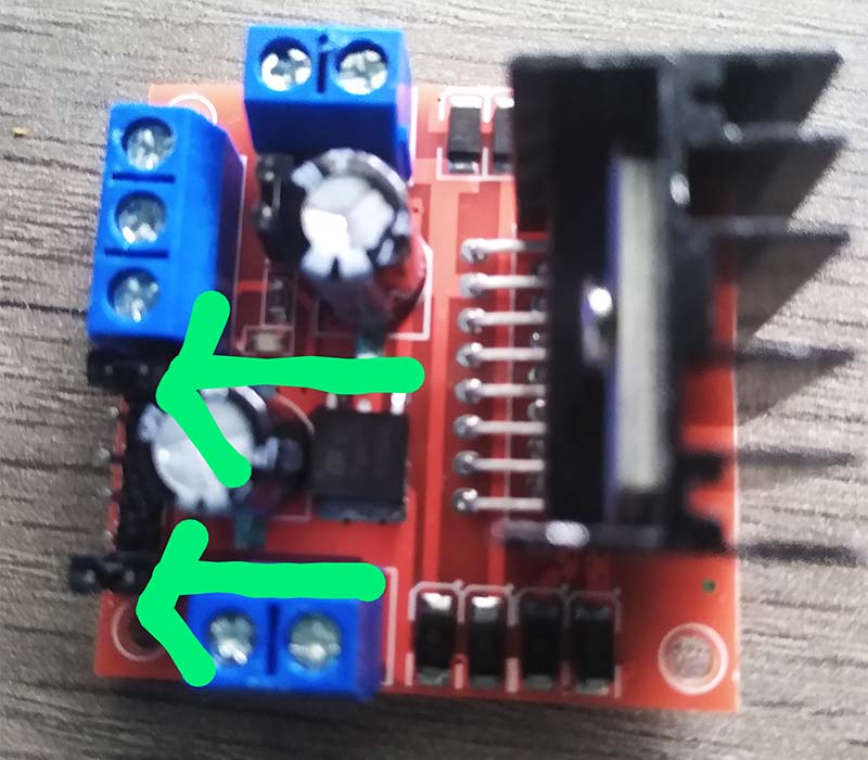
Figure 4: L298N motor controller.
However, when removing the pins and adding jumper wires as shown in Figure 5, the speed of the motors can be controlled through hardware.
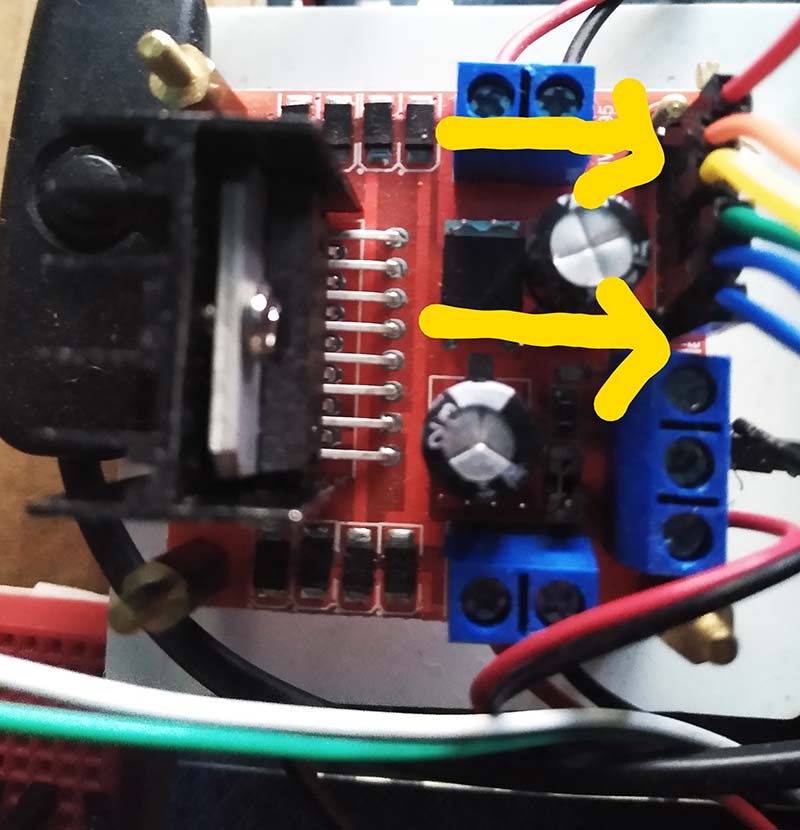
Figure 5: L298N motor controller with jumper wires connected to the enable lines controller with jumper wires connected to the enable lines.
To do this, it’s necessary to use the OutputDevice and PWMOutputDevice classes for speed control. When setting a value with PWMOutputDevice, the speed of the motors will either increase or decrease. Not all motor controllers are capable of this. For example, the Cam Jam Edukit 3 motor controller board can’t use speed control via hardware as it doesn’t have enable pins or even pins that can do that.
To run these robots on any platform, it’s necessary to make some changes to the code to reflect this. In my case, I was able to use hardware PWM on Linus. However, if you have two robots that can use hardware PWM, then you can alter the code to reflect that.
In the Python file dual_movement_gui, instead of importing Robot and CamJamKitRobot, I instead imported OutputDevice and PWMOutputDevice. I then defined the pins for both Linus and Torvalds and then added the pin factories for each. I also had to set the pins for the PWMOutputDevice class.
Next, I defined a function for each direction for both robots where each pin is either on or off. I also defined two new functions (pwm_one and pwm_two) to control the speed of the motors.
I then created two new sliders under the servo sliders that allow the user to control the speed of the motors. Figure 6 shows what the code looks like running under Ubuntu. In the next few sections, I’ll cover the process to run this project on Linux, Windows, and MacOS.
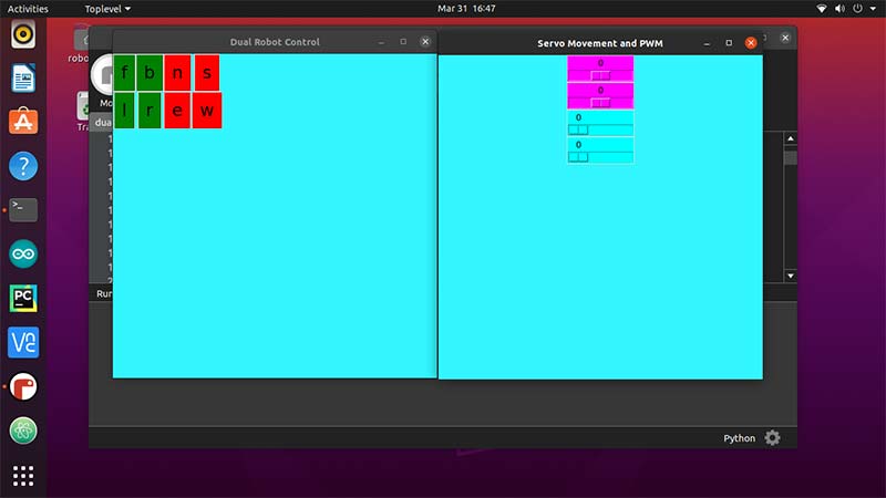
Figure 6: Dual_movement_gui.py running on Ubuntu.
Linux
To run this on Linux, you must first update your repositories. For example, if you’re using Ubuntu, use the sudo apt update. However, if you’re using something like Fedora, you would use the sudo dnf update. Consult the documentation for your specific distro.
The next step is to install pip. Again, if you use Ubuntu, use sudo apt install python3-pip. Sudo is a command that is used to give you elevated privileges. Without it, you can’t install, update, or upgrade. Next, it’s necessary to install the needed modules. So, with sudo pip3, install gpiozero pigpio guizero.
Now, if you’re running Python 3 in a virtual environment, then you can use sudo pip install gpiozero pigpio guizero. Next, since this code can’t be run in a terminal, install an IDE such as Mu, Thonny, or Spyder. Follow the instructions for the specific IDE you want to install. Make sure to access both robots using SSH and then enable pigpio using sudo pigpiod. You can then run it on that IDE and it should work. Again, Figure 6 shows it running using Mu on Linux.
Windows
This is much more complicated as Python is not installed by default on Windows. First, you must install Python from the official site and follow the instructions. Optionally, you can set your environmental variables so that Python always points to Python 3. Then, install the needed modules with pip3 install gpiozero pigpio and guizero.
Again, you can use any IDE to run the program, but make sure to follow the instructions to install the needed IDE. Before you can run things, you must add SSH into each robot. Since Windows has no SSH installed, use a program like PuTTY which allows for remote sessions. Then, enable pigpio on both robots with sudo pigpiod. Figure 7 shows how it runs on Windows.
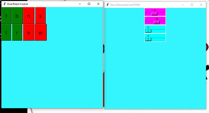
Figure 7: Dual_movement_guy.py running on Windows.
Mac OS
To install it on Mac OS, you can install it using Brew with the command brew install python; pip will be installed by default with this method. However, you can also install Python from the main site. In this case, you’ll have to download get-pip.py since pip is not installed by default.
After that, you can install the needed modules with pip3 install gpiozero pigpio guizero. Again, download any IDE you wish, and it should run with no modification of the code. Also make sure to access both robots with SSH as it is built into Mac OS. Also make sure pigpio is enabled on both robots by using the sudo pigpiod command.
Conclusion
Regardless of which method you use, both robots should now be able to move around and the arm should move with the sliders. You should also be able to run either one or both robots by setting the speed for the motors.
If you have enough space, you can have them running around. If you’re using an Android or iOS device, you should be able to move around with them. Using your Android or iOS device would be almost like using a fancy remote controller, but now you’re controlling two robots instead of one.
In fact, you can extend this to three, four, or however many robots you want to control. The possibilities are endless, and the only limits are your imagination. Hopefully, this inspires you to enter the field of robotics and have fun with it.
I hope you’ve learned that it’s possible to control both robots at once and optionally record as well. Technically, you can actually control more robots this way if you plan to upscale it.
Just make sure you define the pin factories for those robots and also define buttons for those robots. The possibilities are endless. SV
RESOURCES
Getting Started with GUIs Link
https://projects.raspberrypi.org/en/projects/getting-started-with-guis
My Repository for Linus and Torvalds
https://github.com/sentairanger/Dual-Robot-Guizero-Control
Create Graphical User Interfaces with Python Blog Post
https://www.raspberrypi.org/blog/create-graphical-user-interfaces-with-python
Devastator Tank Mobile Platform that I Used for Torvalds
https://www.dfrobot.com/product-1219.html
Cam Jam EduKit 3
https://camjam.me/?page_id=1035
Raspberry Pi Camera Mount
https://www.thingiverse.com/thing:3155461
gpiozero
https://gpiozero.readthedocs.io/en/stable
guizero
https://lawsie.github.io/guizero/about
Installing Python on MacOSX
https://docs.python-guide.org/starting/install3/osx
Installing Python on Windows
https://www.howtogeek.com/197947/how-to-install-python-on-windows
VNC Viewer Main Download Site
https://www.realvnc.com/en/connect/download/viewer
Article Comments