Using GUIs to Control Two Robots
By Edgardo Peregrino View In Digital Edition
For me, the Raspberry Pi is king when it comes to robotics and DIY in general.
I’ve used Raspberry Pis for robots for about three years now, and I’ve evolved my skills. For the last few years, I’ve had two robots in my home named Linus and Torvalds. (Yes. It’s not hard to guess why I gave them those names.) This project was conceived of when I learned about the Python module guizero from the Create Graphical User Interfaces with Python by Martin O’Hanlon and Laura Sach.
I experimented with using LEDs and servo motors before I scaled that up to both my robots. Here, I’ll explain the process, as well as walk you through the code to understand what it does so you can try it yourself.
Getting Started
Before I begin, I want to detail the software and hardware I utilized and alternatives that you can use on your own. For the hardware, as mentioned, I used both of my robots (Linus and Torvalds) which I had from previous projects. Here’s the list of items I used to build Linus and Torvalds, respectively:
Linus
- Generic robot car chassis.
- CamJam Edukit 3, motors and wheels.
- Jumper wires.
- L298N motor controller.
- CamJam Edukit 3, 6V battery pack.
- Cardboard (for the face and servo arm).
- Gray and green paint (for the face and the servo arm).
- Two PC style power LED connector cables (for the eyes).
- Raspberry Pi Zero W.
- Raspberry Pi Zero W case.
- Plasticard (to mount the Pi and L298N).
- Two 9g servos.
- CamJam Edukit 3, breadboard (for the servos to avoid using both 5V rails).
- Standoffs for the L298N.
- 32 GB micro SD card.
- 5V 2.1A USB power bank.
- Micro USB cable with power switch.
Torvalds
- DF Robot Devastator Tank Mobile Platform.
- Two PC style HDD LED cables (for the eyes).
- LED Bezels.
- Raspberry Pi 3B+.
- 32 GB micro SD card.
- Cam Jam Edukit 3, motor hat.
- Plasticard and standoffs for the Pi 3B+ and the base of the robot.
- Six AA batteries (for the motor).
- Raspberry Pi camera.
- 3D printed camera mount.
- 5V 3A USB power bank (to power the Pi).
- Jumper wires for the LED eyes.
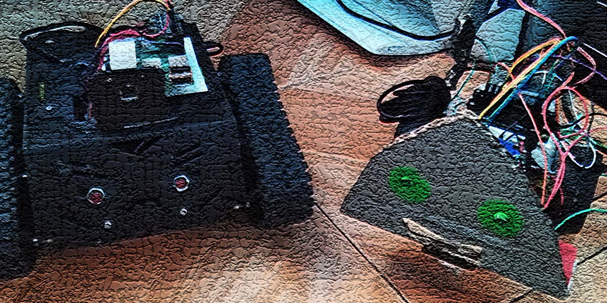
Figure 1 shows the final product after assembling both robots. I should note that if you want to try this on your own, I recommend the CamJam Edukit 3 from Pi Hut. In fact, you can use any motor controller board and any other materials you desire for your robots. Hopefully this helps you with your options.
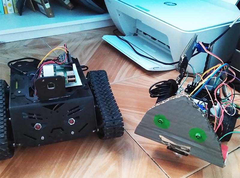
FIGURE 1. My robots, Torvalds (left) and Linus (right).
Also, don’t be afraid to DIY since sometimes we’re on a budget. I created the servo arm from cardboard and two 9g servo motors since it was much cheaper to use. Also, please consult your motor controller board docs if you’re going to use a different motor board from the ones I used in this project.
Try to use an external power supply for the servos if possible. I used a breadboard and then connected the 5V rail to it so that both servos can tap into the 5V power.
To control both robots, I used my RaspPi 4 installed with Raspberry Pi OS. I had to make sure I had guizero installed as well. I’ll explain more about that in the Code Explanation section.
For the software on both robots, I used Raspberry Pi OS Lite on Linus since I didn’t need a desktop and so I can access it using SSH. The way to do this is by adding an empty file called ssh into the boot directory of the SD card and then adding a file called wpa_supplicant.conf. The file should look like this:
ctrl_interface=DIR=/var/run/wpa_supplicant GROUP=netdev
country=US
update_config=1
network={
ssid=”Home Wifi”
psk=”mypassword”
key_mgmt=WPA-PSK
}
Also make sure this is added to the boot directory of the SD card. Eject the card and then it will automatically connect.
To find the Pi’s IP address, you can check your router and then SSH into it. On Torvalds, I had already installed the RaspPi OS desktop version since I needed it to access the RaspPi camera.
Other software that is optional but not needed is VNC Viewer. This is only needed to access the desktop and to use the Pi camera. I should mention if you’re going to use the camera, go into Preferences > Raspberry Pi Configuration > Interfaces > Camera and click enable. If you’re on the terminal, use sudo raspi-config to enable the camera.
For the Python modules, gpiozero, guizero, and pigpio are needed. For gpiozero, the current version didn’t work for the motors or the robot classes, so I had to type this command for it to work:
sudo pip3 install [url=https://bennuttall.com/files/gpiozero-1.5.2b1-py2.py3-none-any.whl]https://bennuttall.com/files/gpiozero-1.5.2b1-py2.py3-none-any.whl[/url]
This is a newer version of gpiozero that is in beta, but the motors will work. One last thing, this experiment only works on a RaspPi for now. You can use the Pi 3 or any other model to control the robots.
Code Explanation
Let’s walk through the code itself to help you understand what each line does. We’ll start with dual_improved_movement.py.
First, it’s necessary to import the needed libraries. Guizero is a module that is used to create fun GUIs for games or even things like meme generators. It can even be used with the Pi camera to display pictures. Here, I imported the App, PushButton, Slider, Text, and Window classes.
The App class is needed to create the overall app. PushButton is a button that can be used to execute whatever command is given. Slider is used to create a slider for various tasks. Text is used for text and Window opens another window so that the user can add more widgets such as text, text boxes, or even buttons.
Next, I imported gpiozero. Gpiozero is used to control the LEDs, motors, servos, and other devices. PiGPIOFactory is imported from gpiozero.pins.pigpio in order to connect to the other Pis remotely. In the next line, I defined the app by giving it a name and a layout which is “grid.” I created a window called Servo Movement and as you see in the first argument, you need to reference where the widget will be placed, which in this case is in App. I then give it an optional color for both windows using the RGB color coordinates. You can use the HTML codes website if you wish to make your own color.
Next, I set up the pin factories for both robots. Make sure to put the IP address for each robot correctly. In my case, I used my router to find the IP address of both Pis. Next, I define the robots using the Robot and CamJamKitRobot classes as the CamJam EduKit 3 has its own library.
In the Robot class, I defined the left and right motors, which in this case are 13, 21, 17, and 27. You can use any pin you want; just make sure you alter it. Also be sure to reference the pin factory for both.
We need to import the AngularServo class because we need a way to control the arm with precision. I defined servo and servo_two where I first assigned the pin number, the min and max angle values, and then the pin factory. I should note that min and max values will be different for each servo.
Moving on, I defined the functions for movement. In this case, they are direction_one, direction_two, direction_three, direction_four, north, south, east, west, stop, and stop_two. I then define the two functions for the servo movement which are servo_movement and servo_two movement. In both functions, when I move the slider, the servo will move based on the angle. For example, if I move the slider to 22, then the servo will move to 22 degrees.
To define a button, I give each button a unique name and then use the PushButton class. First, I added App to reference where the button will be placed. If I was using another window, I would replace it with the name of that window. I then give it some text and create a grid layout to give the coordinates for the button.
For example, the direction_one button has a grid position of [0, 0]. Remember, in Python the numbering system starts with zero not one. Next, I gave the buttons a text size of 20 and then used the bg argument to give them a background color. There are two other arguments I gave to each button: when_left_button_pressed and when_left_button_released.
The first one will execute the given command when you press the button. The second one will execute the other command when you release the button. For example, if I click button1, Linus goes forward. If I release it, Linus stops. This allows for more precise movement.
Let’s discuss the sliders. First, I named both sliders and then defined them using the Slider class. I passed the servo_window option as I wanted to have them on that window rather than the main app. I gave them a start and end value exactly like the servo angles I gave to both in the AngularServo class. Then, of course, I gave them a grid position but this is optional. I gave them both a background color of magenta, and finally in the last line, I used app.display() to display the App.
To run the code, I used Mu but you can also use Thonny or even Geany if you choose to. This code will not run in a terminal, so be aware of that. Once that’s done, your results should look similar to Figure 2. Go ahead and click the buttons to control each robot. Move the sliders around to see the servos move based on the angle you give them.
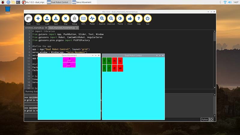
FIGURE 2. Screenshot of dual_robot_pwm.py being run on Mu.
Thankfully, dual_robot_pwm.py is exactly the same, so I don’t need to explain all the lines, but there are some added features that I do need to discuss. This time, I also imported the TextBox class to control the speed of both robots.
First, I added a title to the text box named pwm_title where I first passed the app argument and then gave it the text value of “Set PWM.” I also set the grid position at [4,0]. I then added a text box where I passed the app argument and then gave the grid position of [4,1].
For this to work, I defined the function speed_control where it takes the value of the text from the text box and converts it into an integer but divides it by 10. This is done because the speed of the robots and motors can only be between 0 and 1. This way, when I input a value like 3 for example, the actual value passed is .3.
You have to reference this in the forward, backward, left, and right actions by adding speed=speed_control() inside the parenthesis. For example, for forward, it would look like forward(speed=speed_control). So, when you run the code, it should look similar to Figure 3. Type in a value between 0 and 10 and watch the robots move either slow or fast.
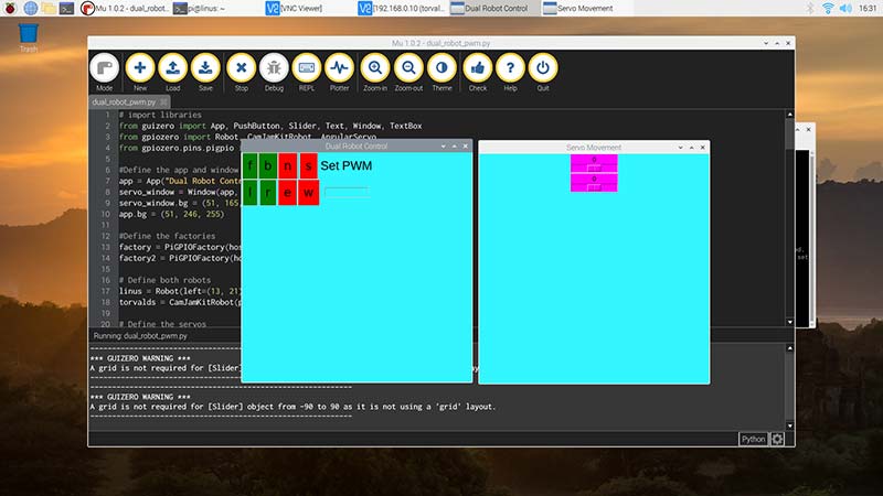
FIGURE 3. Screenshot of dual_improved_movement.py being run on Mu.
In the final code (this is purely optional), if you added a camera to your robot this next step is necessary. In this case, I had VNC enabled already by going into Preferences > Raspberry Pi > Configuration > Interfaces > VNC and clicked on enable. Then, I installed VNC Viewer on the Pi 4 to access Torvalds. (Make sure the camera is enabled before attempting this.) In VNC, you’ll also have to enable the camera by going into Menu > Options > Troubleshooting and select Enable Direct Capture Mode. From there, you can access the desktop and run the camera_guizero.py function.
In this code, I first imported guizero, gpiozero, and the picamera modules. For guizero, I imported the App, PushButton, and Text classes. For picamera, I imported PiCamera and for gpiozero, I imported the LED class since I wanted to use the LED eye from Torvalds to indicate that recording has started.
I also imported datetime to give the video files different labels. Here, I set up the camera with a name, a resolution of 640 by 480, a frame rate of 25, and used pin 25 for the LED.
Next, I defined the capture_camera and stop_record functions. One turns the eye on and then starts recording by using the moment.hour, moment.minute, and moment.second options. This gives the videos unique titles based on the timestamps. The next one simply stops recording and turns off the LED.
Next, I defined the app with the title “PiCamera Recording,” gave it a background color, and then added a title labeled “Camera Recording.” Then, I defined the buttons record and stop.
First, I passed the app argument and then the command argument and provided the functions for each button. I gave both buttons a background color and text size. I then displayed the app with app.display(). The final result should look similar to Figure 4.
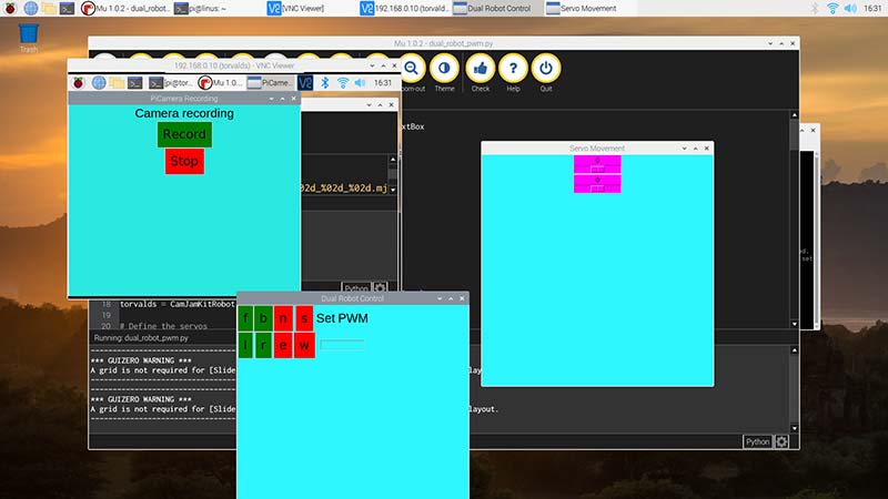
FIGURE 4. Screenshot of dual_robot_pwm.py and camera_guizero.py.
From there, you can turn the camera on and record your surroundings. You can even record the other robot moving and then use it to play omxplayer.
Conclusion
Hopefully, you learned that it’s possible to control both robots at once and optionally record as well. Technically, you can actually control more robots this way if you plan to upscale it. Just make sure you define the pin factories for those robots and also define buttons for those robots. The possibilities are endless. SV
Dedication
I want to dedicate this to my dad who sadly passed away from Covid. He was one of the biggest reasons why I ventured into this project and has always encouraged me to do better. I will miss him, and I hope he is proud of the work I did. I also dedicate this to those closest to me: my grandma, my neighbor Vicente, and, of course, my physics teacher Paul Cain.
Resources
Getting Started with GUIs
https://projects.raspberrypi.org/en/projects/getting-started-with-guis
My Repository for Linus and Torvalds
https://github.com/sentairanger/Dual-Robot-Guizero-Control
Cam Jam EduKit 3
https://camjam.me/?page_id=1035
New book: Create Graphical User Interfaces with Python
www.raspberrypi.org/blog/create-graphical-user-interfaces-with-python
Raspberry Pi Camera Mount
https://www.thingiverse.com/thing:3155461
Devastator Tank Mobile Platform that I used for Torvalds
https://www.dfrobot.com/product-1219.html
gpiozero
https://gpiozero.readthedocs.io/en/stable
guizero
https://lawsie.github.io/guizero/about
Article Comments