Recreating the Red Light, Green Light Doll from Squid Game
By Katherine Fernandes, Tiffany Guo View In Digital Edition
With her beady black eyes, lively yellow dress, and two adorable pigtails, what isn’t there to love about the doll from the hit Korean television series, “Squid Game?” Well, maybe it’s the fact that she comes with a motion-sensing artillery system — a system that makes the Squid Games very “high stakes.”
Inspired by our love for the show and microcontrollers, we decided to recreate the fully functional Squid Game Doll which facilitates a game of Red Light, Green Light; identifies the movement of players during the Red Light phase; and performs a special action when a player wins the game.
System Overview
If you’ve ever played the classic Red Light, Green Light game as a child, you’ll know that the objective of the game is to tag the player at the other end of the room without letting them catch you moving. Players start out on one side of a room while one person stands at the opposite end, repeatedly alternating between the Green Light phase (where they face their back to the other players) and the Red Light phase (where they turn around and look for movement).
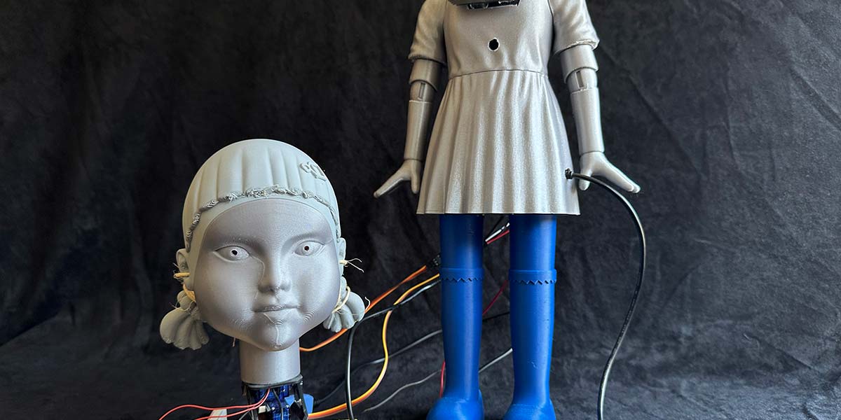
Our inspired version of Red Light, Green Light is the same, just with additional “consequences.” Beginning with her head facing away from the players, the doll (Figure 1) sings a classic children’s song while players can move towards her.
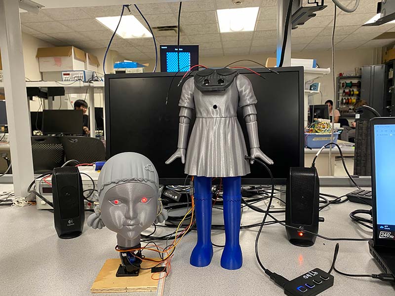
Figure 1 - The doll (front view).
Her head turns around after she finishes singing, at which point the players must remain still to stay in the game.
The doll repeats this pattern until a player gets close enough during the Green Light phase to win the game. However, if a player is caught moving, they are eliminated permanently. To bring our design to life, we outfitted our doll with a PIR motion sensor, ultrasonic sensor, LEDs, audio jack socket, and multiple servomotors.
As noted, the game operates in two phases. During the Red Light phase, the doll senses motion and flashes her red eyes to indicate a player’s elimination. During the Green Light phase, the ultrasonic sensor is used to detect if any players reached a threshold distance from the doll and won the game.
The audio jack socket plays an audio-synthesized version of the children’s song from the show, and servomotors work to turn her head when transitioning between the two phases.
Schematic
The doll system can be simplified into three subsystems: sensors, motors, and audio synthesis. An RP2040 microcontroller drives the system and an external 5V battery is used to power it. Figure 2 shows a schematic of the system.

Figure 2 - Hardware schematic.
State Diagram
The flow of the Red Light, Green Light game is best represented using a finite state machine (FSM) with five states to depict the three stages of the system: Green Light, Red Light, and Win. The system boots into the Green Light stage, alternating between state 0 and state 1 as the children’s song plays and the ultrasonic sensor measures the player’s distance from the doll.
After the song finishes and a player has not won, the system shifts to the Red Light stage (state 2) where the motion sensor checks for movement to light up the eyes. After five seconds, the system transitions back to state 0 in the Green Light stage.
If the player wins by triggering the ultrasonic sensor, the system enters the Win stage, alternating between state 3 and state 4 as the winning song is played on repeat. Figure 3 shows a visual diagram of the FSM along with Table 1 which gives more detailed descriptions of each state.
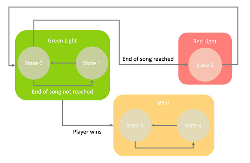
Figure 3 - Finite state machine.
| State | Description |
|
State 0: Green Light - Song Notes Play State 1: Green Light - Pauses Between Song Notes |
The system boots into Green Light and the audio-synthesized children’s song is played by alternating between state 0 and state 1 until the last note is played, at which point the state changes to state 2. The ultrasonic sensor checks if a player is within 30 cm of the doll, which then triggers the state to be changed to state 3. |
| State 2: Red Light - Pauses Between Songs | The doll turns its head 180 degrees to face the players and the song stops playing. The PIR motion sensor checks for motion. If motion is detected, the doll’s red LED eyes light up. After five seconds, the state changes back to state 0. |
|
State 3: Win - Song Notes Play State 4: Win - Pauses Between Song Notes |
When a player wins, the head falls backwards and the winning song is played through audio synthesis. The states alternate between state 3 and state 4. The winning song restarts once the last note is played. (The only way to end the loop of the winning song is to reset the Raspberry Pi). |
Table 1: Finite state machine description
Components
“Voice” - Songs using Audio Synthesis
The children’s song audio was synthesized in two parts (Figure 4).
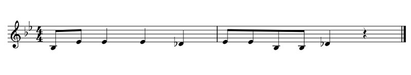
Figure 4 - Korean children’s song “When the Hibiscus Flower Blooms.”
First, we determined the frequency and duration of each of the notes in the song. Then, we generated the notes using an external digital-to-analog converter (DAC) and output them to the audio jack.
To find the frequencies and note durations, we listened to the song by ear and transcribed the notes. Then, we matched each note to its corresponding frequency with the help of an online conversion website. The song only had eight notes and quarter-notes, so we defined two note durations with a quarter note being double the duration of an eighth note.
To generate these notes in sequence, we first stored the frequency and duration values we calculated in two separate arrays. To generate a note, we implemented Direct Digital Synthesis (DDS): an algorithm which generates a sine wave using a digital incrementer. We adjusted values for the amplitude, ramp-up and ramp-down durations, and frequency in order to produce our desired notes. Then, we simply loop through both arrays and generate each note.
A key aspect of Red Light, Green Light is that the timing of each stage is unpredictable. In order to keep players on their toes, the song can be played faster or slower each time. To emulate this in our game, we generate a random scaling variable which is multiplied with elements in the duration array. The range of the variable is from 0.5 to 1.5, where the song plays faster if the value is between 0.5 and 1.5, and the song plays slower if the value is between 1.0 and 1.5.
Lastly, we used a DAC to convert our digitally synthesized children’s song to an analog output for the audio socket, which is connected to a speaker.
Links to Our Final Project
Project Website: https://ece4760.github.io/Projects/Fall2022/tg382_kaf245/index.html
GitHub Repository: https://github.com/klarinetkat/ECE-4760-Squid-Game
“Head” - ServoMotors
The detached head of the doll is controlled by two servomotors. One motor rotates the doll’s head 180 degrees on the X axis during the transitions between the Red Light and Green Light phases. The second servomotor controls the Y axis to hold the head upright during the game and allows the head to fall backwards when the player wins.
A PWM signal from the Raspberry Pi controls the angle of the servomotors. Each servo is mapped to a separate GPIO pin with PWM capabilities. The RP2040 microcontroller has a total of eight two-channel slices which means there are 16 PWM channels available for use. The benefit of using two channels from the same slice is that you only must configure the period of the PWM signals once and you can set different duty cycles for each channel. We ended up using one channel for the X axis servo and the other channel for the Y axis servo.
We configured the PWM period with a clock divider of 250 and a wrapVal of 10000. The CPU rate of the RaspPi Pico is 125 MHz, so the frequency of the square wave for the micro servo is 50 Hz. We can use the wrapVal to estimate the duty cycle of the servomotors. The wrapVal represents the range of values we can choose for the PWM duty cycle. For the servo to turn to a specific position between 0 degrees and 180 degrees, we set our duty cycle to be 0% to 10% of the wrapVal.
Parts
3D-Printed Doll
PIR Motion Sensor: https://www.adafruit.com/product/189
Ultrasonic Sensor: https://www.sparkfun.com/products/15569
Mini Pan-Tilt Kit for Micro Servos: https://www.adafruit.com/product/1967
Raspberry Pi Pico: https://www.digikey.com/en/products/detail/raspberry-pi/SC0915/13624793
DAC: https://www.digikey.com/en/products/detail/microchip-technology/MCP4822-E-P/951465
Speakers
Audio Socket: https://www.digikey.com/en/products/detail/cui-devices/SJ1-3553NG/738710
AUX Cables: https://www.digikey.com/en/products/detail/assmann-wsw-components/AK203-MM/821672?s=N4IgjCBcoLQBxVAYygMwIYBsDOBTANCAPZQDa4ATAMwgC6AvvYRWSAIIDSFADFQPQBZAXXpA
“Eyes” - Sensors and LEDs
PIR Motion Sensor
For the Red Light stage, we use a PIR motion sensor to detect movement from the players. We made sure to set both the sensitivity and delay settings to their minimum value in order to receive information from the PIR sensors as quickly as possible.
Our PIR motion sensor is connected to a GPIO pin as an input with a software implemented pull-up resistor. The PIR sensor returns 1 when it detects movement and returns 0 when there is no movement. Based on this information, we control the doll’s red eyes with another GPIO pin connected to a simple LED circuit consisting of a 1 kΩ resistor and two red LEDs in parallel. The red LEDs light up when the GPIO pin is driven high and turn off when driven low.
Ultrasonic Sensor
For the Green Light stage, we use an ultrasonic sensor to detect whether a player is within our “winning range” of 30 cm from the doll. The ultrasonic sensor uses two GPIO pins for the trigger and echo functionalities.
It was tricky to program the transition to the Win state. Our original logic was to check if the ultrasonic sensor detected a measurement of less than 30 cm. However, we noticed during the transition of going between Red Light and Green Light, the ultrasonic sensor senses 0 cm. To work around this, we implemented a for loop that takes three measurements and determines whether or not all three were within the winning range. If they all are, then we transition to the Win state; if not, then we transition back to Red Light.
“Body” - 3D Printed Doll
The doll was 3D printed piece by piece and assembled using hot glue. We used the 3D printer models modified by Jason Altice P.E. from CodeMakesItGo. The inside of the doll is hollow to allow for storage of the hardware, and there are holes in the body of the doll for peripherals such as the ultrasonic sensor, motion detector, and LEDs (Figure 5).
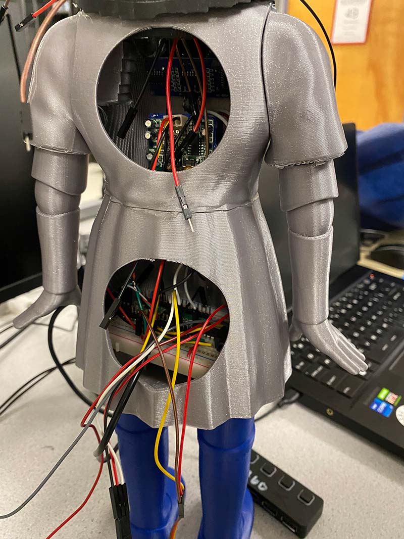
Figure 5 - Doll’s body (back view).
Results
The final product of our project is a fully functional Red Light, Green Light doll. The doll consists of the integrated sensor, motor, and audio synthesis systems, and it implements the logic from our finite state machine. The final design is a little different from our initial idea due to the difference in the placement of the head, which is decapitated from the body.
In addition, the game mainly functions as a single player version of Red Light, Green Light. The motion and ultrasonic sensors have no way of differentiating which player wins or loses, and the game ends after one player wins. For now, human judges will have to call the shots. SV
References
Raspberry Pi Pico Datasheets:
https://datasheets.raspberrypi.com/rp2040/rp2040-datasheet.pdf
https://datasheets.raspberrypi.com/pico/raspberry-pi-pico-c-sdk.pdf
https://datasheets.raspberrypi.com/pico/pico-datasheet.pdf
https://datasheets.raspberrypi.com/pico/Pico-R3-A4-Pinout.pdf
CodeMakesItGo (.stl files of doll): https://github.com/CodeMakesItGo/SquidGamesDoll
KleistRobotics (ultrasonic sensor): https://github.com/KleistRobotics/Pico-Ultrasonic/blob/main/ultrasonic/ultrasonic.c
Tom’s Hardware (PIR motion sensor with Pico): https://www.tomshardware.com/how-to/raspberry-pi-pico-motion-sensor
ECE 4760Course Website: https://ece4760.github.io/
Article Comments