Servo Magazine ( May 2012 )
Building Maxwell: Mechanics, Electronics — Part 2
By Michael Ferguson View In Digital Edition
Previously, I briefly introduced the new MX-series of Robotis Dynamixel servos and how these servos can help in building a mobile manipulator. This article will take a step back through time to show the development and evolution of the mechanical and electrical side of my mobile manipulator — a robot called Maxwell.
Motivation
There were a number of design goals with the development of Maxwell. First and foremost, I very much wanted to avoid the hassle of setting up a test environment for my robot (as I had long needed to do when building smaller competition robots). I needed a robust mobile manipulator that could operate in a typical home environment. I decided that I didn't particularly want to have to work mainly on things on the floor, and so the arm was targeted at a table top height. As I was frequently transporting my robot to various demos, it really needed to be easy to carry around and/or ship. The goals became:
- To use as much open source hardware and software as possible.
- To be low cost, by using off-the-shelf components wherever possible. Custom parts are mostly laser-cut ABS sheet stock.
- To be human scale, without sacrificing portability.
- To have robust onboard sensory/computation.
From this set of requirements, I developed a fairly straightforward base and torso, since I generally prefer to be writing software rather than debugging hardware or mechanical problems.
Evolution
People often ask me "Which version of Maxwell is this?" The truth is, Maxwell has slowly evolved over the past year and a half, and has undergone a number of revisions. The original build of Maxwell occurred in January 2011, with some minor updates over the following month. The version shown in Figure 1 used a mix of AX-12 and RX-64 servos, and had no vertical movement for the arm.
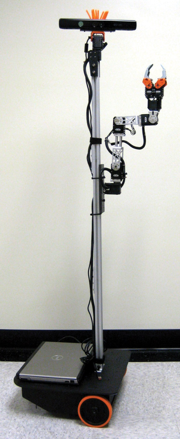
FIGURE 1. Maxwell, circa March 2011.
In late 2011, Maxwell got a new head, replacing the large Microsoft Kinect with a much smaller Asus Xtion sensor. This greatly improved the performance of the neck servos. At this time, I also added a vertical linear actuator for the arm so that it could reach the floor, as well as tabletops. Unfortunately, the portability was sacrificed because Maxwell no longer fits in his handy pelican case for transport (at some point, I hope to remedy that). In early 2012, I upgraded the RX-64 servos to new MX-64 servos which have a much higher resolution encoder, as well as being designed for my 12V power system, which also allows me to use a single bus for all the servos. Maxwell, as he stands today, is shown in Figure 2.
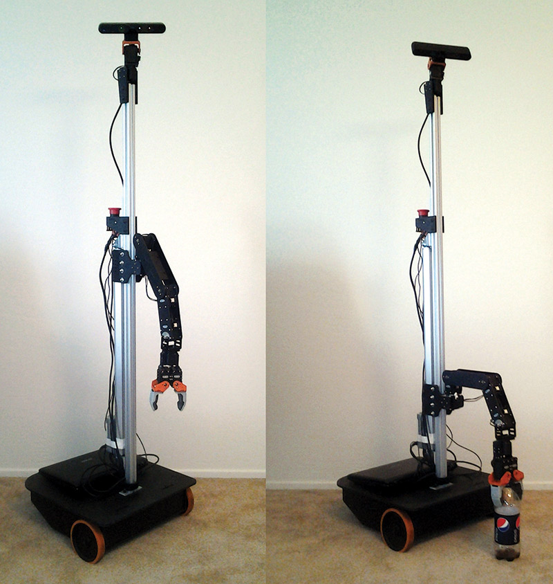
FIGURE 2. Maxwell.
The entire robot was designed in Autodesk Inventor, allowing parts to quickly be exported for laser cutting, and avoiding costly revisions that might have been caused by parts not fitting together. Figure 3 shows the robot as rendered in Inventor.
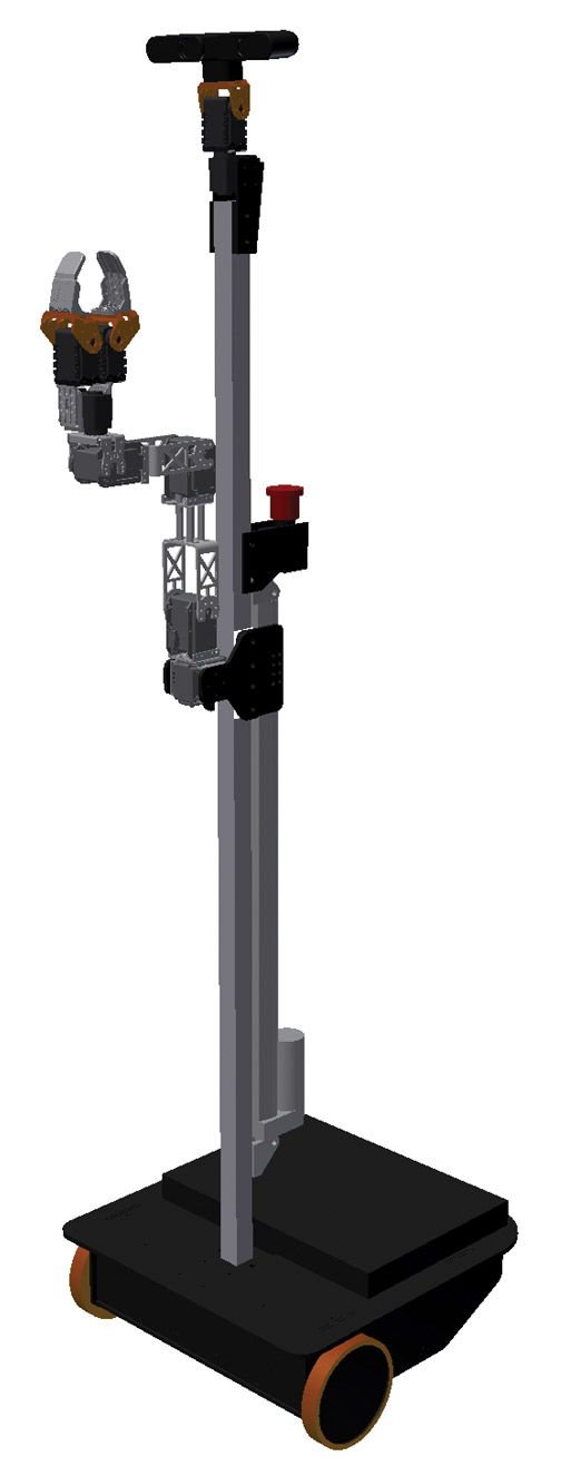
FIGURE 3. Maxwell as designed in Autodesk Inventor.
The Base
The mobile base is fairly simple but very robust. It has a 16" x 16" footprint and is constructed of mostly 3/16" thick laser-cut ABS. The pieces go together using a collection of tabs and slots, and are held in place using small #4-40 corner brackets (Digi-Key P/N 621K-ND). This construction method has proven to be quite reliable on Maxwell, as well as in other projects.
The base uses a differential drive setup with two DC gearhead motors from Zagros Robotics (www.zagrosrobotics.com) which can power the robot to speeds of up to 2 ft/sec. The BaneBots (www.banebots.com) wheels provide a sturdy grounding, with lots of grip. I had to drill out the 6 mm hubs on the wheels to attach them properly to the 1/4" shafts on the motors, but other than this quick modification, the entire base can be assembled with just a set of hex keys. The battery is tie-strapped down, and held in place by the same piece of ABS that forms a socket for the 8020 column to insert into. Wire routing for the power switch and a charger socket is done using a European-style terminal strip and 14 ga wire.
The base design allows a full-size (14.1" screen) laptop to fit on the back deck. The computer interfaces to I/O through a Vanadium Labs ArbotiX RoboController which is tucked in the front of the base. The ArbotiX is used as a co-processor — connected over USB — which handles all real time operations and passes serial commands between the PC and the arm/neck servos, as well as implementing closed-loop PID control of the mobile base. The base is shown in Figure 4 without the top cover or caster (which attaches to the top cover).

FIGURE 4. The base, without top cover or rear caster.
The Torso and Head
Maxwell's torso is very lightweight, constructed of three pieces of 1" x 1" 8020 extruded aluminum. The 8020 offers an easy way to connect everything together and to vary the height of the neck. Maxwell's overall height is about 5 ft tall.
Three pieces of 8020 were used with joining plates, so that Maxwell could easily be broken down for shipment or transport. By loosening only six screws, the entire robot can be broken down and fit into a Pelican case. Figure 5 shows how the three pieces are put into the case.
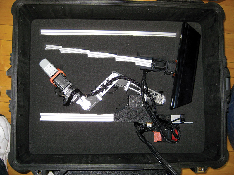
FIGURE 5. Maxwell disassembled for transport and put into the Pelican case. The base fits on top of this (with a layer of foam in between).
A layer of protective foam then covers the components and the base is put on top. This configuration has been successfully shipped across the country several times when traveling to RoboGames and other events.
The head is composed of two Dynamixel AX-12 servos, and allows the Asus Xtion RGBD camera to look all around the robot. This sensor is very much like the Microsoft Kinect, but weighs much less and is much smaller. Mounted on the back of the torso is a big red button. This is the emergency stop which cuts power to all the servos and the base motors. When building a robot this large, an emergency stop is always a good idea because your code will eventually have a bug, and the robot might damage itself or the things around it.
The Arm
Maxwell's arm consists of a five degree of freedom (DOF) manipulator with a two-servo gripper. The arm and gripper use four Dynamixel MX-64 servos and three AX-12 servos. The lowest four joints of the arm are MX-64s for extra strength. A lower cost AX-12 is used for the wrist rotation joint, and for both of the fingers on the gripper.
While a five DOF arm is not capable of as many varied grasps as a seven DOF arm (as found on the PR2), it is quite a bit less expensive to build since the arm itself weighs much less, and you have several fewer joints.
The most recent addition to the arm is the linear actuator which allows it to move up and down about 20". This allows Maxwell to reach things located on the floor, as well as greatly improving the overall workspace of what the gripper can reach. The linear actuator was purchased from Firgelli Automation, and has a speed of about 2"/sec. Unfortunately, it lacked any sort of positional feedback and I had to hack on an optical encoder. I hope to eventually replace the linear actuator with something more compact and quieter when in operation.
Conclusion
This article laid out the mechanical and electrical design, and evolution of my robot, Maxwell. Next time, we will delve into the software used to control Maxwell. While building Maxwell, I documented many of the smaller iterations on my blog which can be found at www.showusyoursensors.com. SV
Parts List
| Frame materials | Laser-cut ABS, mostly 1/8" and 3/16" 1"x1" 8020 aluminum framing |
| Drivetrain | (2) Zagros Robotics REXC motors (2) 4-7/8" BaneBots wheels and hubs (1) 3" caster |
| Arm | (4) MX-64 servos; (1) AX-12 servo (1) 20" linear actuator |
| Gripper | (2) AX-12 servos; Bioloid brackets for fingers |
| Battery | 12V sealed lead-acid, 8 Ah |
| Sensors | (1) Head-mounted ASUS Xtion Pro Live (similar to Microsoft Kinect) mounted on a pan-tilt neck. (1) Hokoyu URG-04LX-UG01 laser |
| Main Processing | (1) Standard laptop; fits on back deck |
| Motion Control | (1) ArbotiX w/ dual 30A motor drivers |
Article Comments