Analog Servos for Robotics
By Eric Ostendorff View In Digital Edition
Servos are motorized gearboxes which move to a certain location or speed specified by a control signal. The focus of this article is on analog servos which are the ones traditionally used in R/C cars and airplanes, and, more recently, are used in hobby robotics. Digital servos will also work, but are often more expensive and consume more power than analog servos. They do offer extra features, but we won't get into those here.
Figure 1 shows three different servo sizes, from a large “quarter scale” servo (left) to a small nine gram servo (right). A standard sized servo (center) measures about 40 mm L x 20 mm W x 36 mm H, and weighs 40-50 grams. The cheapest (~$5-$10) servos use plastic gears and bushings. Better ($30+) ones use metal or “karbonite” gears and ball bearings for bigger loads and longer life.
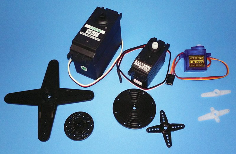
FIGURE 1.
Servos generally require 4.5-6 volts to operate and consume most of the electric power in a robot. While most microcontrollers require very little electrical power and could run on tiny batteries, servos require larger batteries — either alkaline or rechargeable. The minimum practical power supply to drive one or two servos is three AA alkaline cells.
A servo cable has three wires going to its three-pin female connector: ground (usually black or brown); V+ (battery positive, usually red); and the control signal (usually white, yellow, or orange). Polarity is important; always double-check when connecting servos.
SERVOS: INSIDE AND OUT
Figure 2 shows an exploded view of a typical hobby servo. A variety of internal gear ratios are available, delivering different kinds of mechanical advantage. In general, a high gear ratio servo (lots of gear reduction) will deliver more torque/force at a slower speed.
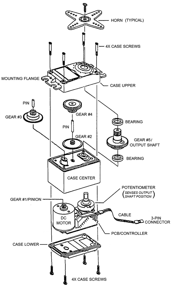
FIGURE 2.
A low gear ratio servo (less gear reduction) will move faster but with less torque/force. Note: Forcing a servo to rotate (when off) can damage it. The particular internal gearing allows some servos to move easier than others. When in doubt, don’t force it!
Some servos will rotate in opposite directions for a given signal. Electronic servo reversers are available for a few dollars, but are generally not needed in robotics as the rotation is easily reversed in software.
Servo specs list stall torque and speed (transit time for 60 degrees) at 4.8 volts and six volts for comparison, plus which direction they rotate when a signal is applied. Electric motors in servos include brushed (standard), plus brushless and coreless (high performance).
In robotics, we use both standard servos and continuous rotation servos. Both respond to standard hobby-protocol pulses, ranging from 1-2 milliseconds (ms) wide. A constant 50 Hz stream of pulses is required to keep the servo energized; one pulse won’t do anything. Pulse widths of 1 ms drive the servo one direction; pulses of 2 ms drive the servo the opposite way; and 1.5 ms is the center of travel. In reality, these numbers give less than 180 degrees of travel, so the pulse range for robotics may vary from 0.50 ms - 2.50 ms to deliver full travel as shown in Figure 3.
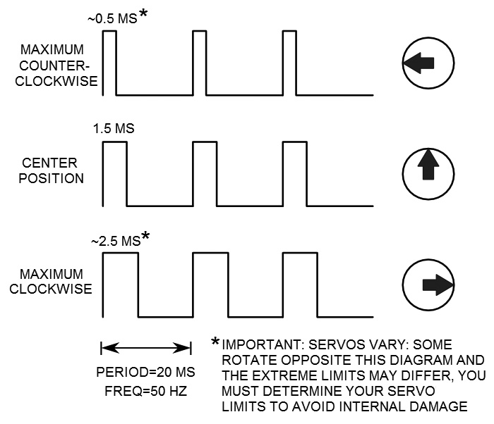
FIGURE 3. Servo Control Signals.
The number of splines on the output shaft varies between brands, so servo horns and accessories are not necessarily interchangeable. Medium sized Futaba servos use 25 splines, while Hitec servos use 24 splines. Not compatible. There are also some minor differences between various brands of female connectors, but nothing that will prevent most brands from plugging into a standard three-pin male connector or PCB (printed circuit board) header. Watch out for pre-1998 Airtronics servos, however, which have reversed power connections and may “release the magic smoke” if hooked up to a standard servo controller.
SERVO TESTERS
Electronic servo testers (Figure 4) are very handy and cheap — some as low as $2. Several servos can be connected at the same time. Most testers have three modes, selectable by a pushbutton switch. Mode 1 allows manual servo control: Twist the knob and the servo rotates accordingly. Mode 2 locks the servo in its center position. Mode 3 oscillates the servo back and forth. Some simple projects might not even require anything beyond a servo tester!
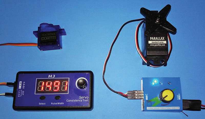
FIGURE 4.
The cheaper testers only send 1-2 ms output pulses which rotate most servos less than 180 degrees. That’s still useful for checking servo motion on a project before a programmable controller is available.
A tester with a built-in display showing the pulse width is extremely valuable. To avoid damaging the tester and servos, always double-check polarity when connecting the battery (also 4.5V-6V) and servos. Connect the battery first to verify the LEDs come on properly before connecting any servos. DIYers can build the simple servo tester shown in Figure 5.
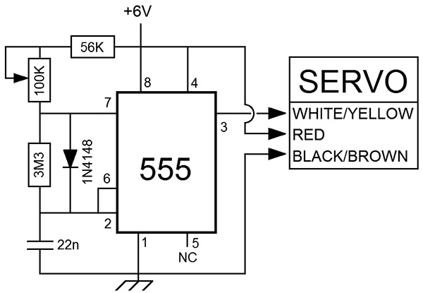
FIGURE 5. DIY Servo Tester
STANDARD SERVOS
Standard servos rotate their output shaft about 180 degrees, or a half rotation. Another way to say it is they move ±90 degrees from their center position. They are used for precise rotational positioning; perhaps moving a robot arm or leg joint, steering a wheel, scanning a sensor, or aiming a laser. An internal potentiometer (rotary sensor) detects the output shaft position and provides feedback to the internal control circuit. This is called a “closed loop” control system.
A servo knows its position and whether it needs to move based on the incoming control signal. It will fight and “growl” to maintain position — even up to the point of breaking or stripping its gears. Extra power is consumed to move a heavy load or to hold a fixed position when strong forces are involved.
Standard servos have internal mechanical stops at each travel limit; often a tab on the output gear which hits a part of the case. On some servos, the output gear is only half a gear (a.k.a., sector) since it only rotates 180 degrees. You’ll waste power and possibly damage a servo if you send a control signal which makes the servo try to rotate beyond its mechanical stops. Every servo is slightly different, so if you plan to drive a servo to its mechanical limits you need to test it individually and determine the custom control signals (numbers in the program) which correspond to its mechanical limits.
Standard servos rotate slightly on power-up — even with no control signal applied. The rotation will consistently be either CW or CCW, depending on the servo. Usually this is not a problem, but here’s one example where it is. Sometimes I use a servo to mechanically trigger various one-shot mechanisms when rotated to different positions. It’s possible that something would unintentionally trigger on power-up when the servo moves slightly. To avoid this, I build my mechanism so that it triggers when the servo moves in the opposite direction from power-up. In fact, I like to use the mechanical limit as the start and end positions in the program, so that the servo is homed against a hard stop and can’t rotate at all when turned on.
Analog servos are dumb. Take that two ways: They are not smart servos with their own microprocessor, plus they can’t talk. As in talk to their controller. They are obedient slaves — and will do their best to move where commanded just as fast as they can go. The servo has its own internal feedback — a closed-loop system that keeps trying to do as instructed. However, the micro never gets any feedback from the servo. The possibility exists that the servo may not have had the power, torque, or time to move to a commanded location. The micro won’t know this. (Bummer, huh?)
Here’s an experiment I did in the course of writing this article. I added one wire to a servo, connected to the center wiper of the position-sensing potentiometer which provides position feedback to the servo’s internal electronics. The potentiometer is a voltage divider, outputting an analog voltage proportional to the output shaft position. If we allow the micro to read that voltage using an ADC (analog-to-digital converter), it can determine the servo’s position. There are numerous ways to do that, based on which microcontroller we’re using.
I used a PICAXE and in an hour or so, I had a modified servo and code that would let me teach a motion sequence by manually moving the servo first, then the PICAXE could play it back. I subsequently found that LadyAda beat me to this with an Arduino. In fact, Adafruit sells hacked servos with the extra feedback wire.
MECHANICAL CONNECTORS
For mechanical connection to the output shaft, servos come with one or more servo horns: plastic connectors which press onto the splined output shaft and are retained by a tiny screw (don’t lose that hard-to-find screw!). They may be circular or have 1-6 arms with many small holes, mainly intended to connect to wire push-pull linkages. Connecting wheels or other parts to servo horns can be a challenge.
Servocity.com sells a wonderfully mind-numbing array of bolt-on servo accessories: wheels, couplers, shafts, hubs, gears, sprockets, and brackets. They are well-designed and straightforward to use. Some accessories cost more than a cheap servo, but spend some time at Servocity.com. There is a wealth of parts and information there. You will surely learn and get ideas. Maybe even buy something.
The robotics/DIY crowd loves to improvise, adapt, and overcome, utilizing the horns which come with the servo. Sometimes tiny nuts and bolts can be used to screw the servo horn to another part. This requires fairly accurate drilling and assembly. If you are fearless and VERY sure of your assembly skills, you can glue parts to the servo horn using only thick gap-filling CA (cyanoacylate, a.k.a., super glue). Don’t waste your time using hot melt glue, which will eventually shift or fail and undo all your careful calibration and programming.
First, drill a mating hole in your part before gluing so you can access the tiny retaining screw. That way, you can still remove the horn assembly from the servo when necessary. The nylon servo horn is very difficult to glue properly. Thoroughly rough up the top and bottom of the horn to be glued with coarse sandpaper or a file. You want visible scratches and gouges all over for good adhesion. Clean off any dust; use good quality thick glue; and alternate layers with accelerator/kicker to build up material and encapsulate the servo horn. Don’t get glue in the servo, obviously, but use plenty of glue with plenty of ventilation. That’s cyanide gas burning your nose, lungs, and eyes.
Many servos include mounting screws and rubber grommets. The grommets are for shock absorbing and vibration damping on model airplanes and cars. They are not used in robotics since they can deform over time, allowing creep and reducing positional accuracy. Servos have mounting flanges for screw mounting. Alternate methods of mounting servos to a flat surface include strong double-sided tape or gluing for a permanant assembly. Hot melt glue can be used, and later removed with alcohol if necessary. Thick super glue as previously discussed is obviously more permanent. As with the servo horn, rough up the outer servo case with sandpaper and clean thoroughly before using glue on the servo.
Like rubber mounting grommets, servo savers are best left to the R/C car crowd and skipped in most robotics applications. These spring-loaded shock aborbers on the steering linkage “give” in a crash to avoid breaking internal gears and to save the servo. Unfortunately, they also give under steady loads and introduce positional inaccuracies that are counterproductive to the precise positioning needed in robotics.
CONTINUOUS ROTATION SERVOS
Continuous rotation servos (CR servos) look like standard servos, but differ internally. They have no mechanical stops and rotate continuously in both directions, making them suitable for driving wheels on a robot.
They have no position sensor to provide feedback to the internal control circuit, so this is an “open loop” control system. The servo will turn forward and reverse at different speeds based on the control signal, but there is no built-in way to verify rotation or distance.
CR servos should stop at a specified control signal (1.5 millisecond pulse) but not all do, mainly because of manufacturing tolerances, temperature stability, etc. Some CR servos can be “nulled” (adjusted) for a precise stop by turning an internal potentiometer with a small screwdriver. Good quality servos are consistent over time; cheaper ones drift and need to be re-nulled occasionally.
It’s noteworthy that when a CR servo is nulled and receiving a stop command (1.5 ms pulses), it is not simply “doing nothing.” It is applying dynamic braking and will resist turning more so than if the servo was unpowered.
CR servos are not terribly fast; 40-50 RPM is typical. Not surprisingly, their top speed increases when powered by higher voltages. I coaxed 60 RPM out of a large CR-modified VS-11 servo by using 7.2 volts, but that risked servo damage. Stick with six volts max. If you need more speed or higher voltage, use an H-bridge with a gearmotor instead of a servo.
Even lacking feedback and being slow and drift-prone, CR servos continue to be popular in hobby robotics. They are fairly cheap, ready to go with a built-in control circuit, and have the familiar servo form factor. Many standard servos can be modified for continuous rotation. Some are easier to modify than others, and some give better fine speed control.
To modify a servo, the internal feedback potentiometer must be disconnected or replaced, and the output gear (and/or case) modified to remove the mechanical stops. Many examples of this popular “hack” can be found on the Web.
Finding wheels to mount on a CR servo can be a challenge. There are some premade wheels which fit directly onto a servo spline (Pololu and Solarbotics sell Futaba spline wheels). Some have the matching female spline molded into the plastic wheel; others have a servo horn attached. You can make your own wheels by attaching a servo horn to some existing wheels using either screws or glue as previously described.
Accuracy is naturally required to center the horn on the wheel. Otherwise, the wheel will be eccentric and make the robot wobble. In the case of gluing servo horns to a wheel, epoxy would be a better choice than CA, since the curing time is minutes instead of seconds.
As the epoxy is curing, you can spin the servo using a servo tester to verify concentricity and nudge the wheel into running true. Be sure to rough up the nylon servo horn to promote good adhesion (also described previously).
If you are handy and have access to some basic shop tools, you can make your own wheels out of a flat plate of plastic, wood, or other soft material. Cut out an oversized circle with a bandsaw, then glue the servo horn firmly to the circle as described, eyeballing the center. Now, mount the wheel on the CR servo and spin it with the servo tester, using a pencil or marker to draw a circle of the right diameter. Next, use a disk or belt sander to make the wheel round — just barely oversize.
Finally, spin the servo/wheel with the servo tester while CAREFULLY holding it against the sander, making it perfectly circular at the desired size. Watch that servo cable and do NOT let it get pulled into the sander!
Two servos I know of come with a 1.75” diameter circular horn — a small but free and instant wheel. This diameter “wheel” gives a forward speed of 5-7 inches/second. Drive wheels need rubber tires for traction, which are often O-rings or rubber bands. A handy source for custom-width rubber band tires is to cut a loop out of a bicycle inner tube, which is what I used on that 1.75” horn. For any given servo and RPM, larger wheels will give higher speed.
I have even seen peanut butter jar lids screwed to servo horns, using rubber band tires to give a good advantage on mobile robots (Figure 6). Get creative!
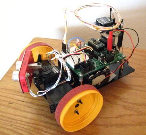
FIGURE 6.
SPECIALTY SERVOS
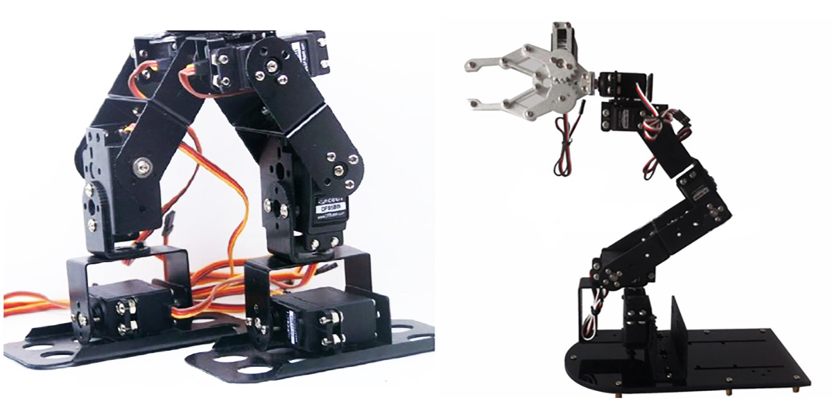
In addition to traditional hobby rotary servos, roboticists are fortunate to have a selection of specialty servos. Robot-specific servos have been created for the humanoid and arm market, as well as brackets and hardware to make complex linkages. At the high end are Dongbu’s Herculex and Robotis Dynamixel digital servos with amazingly high power and capability.
They have encoders, dedicated programmers, and specialized communication protocols — all beyond the scope of this article. Lately, some of their mechanical features are showing up on cheaper digital “robot servos,” such as the LD2015 shown in Figure 7.
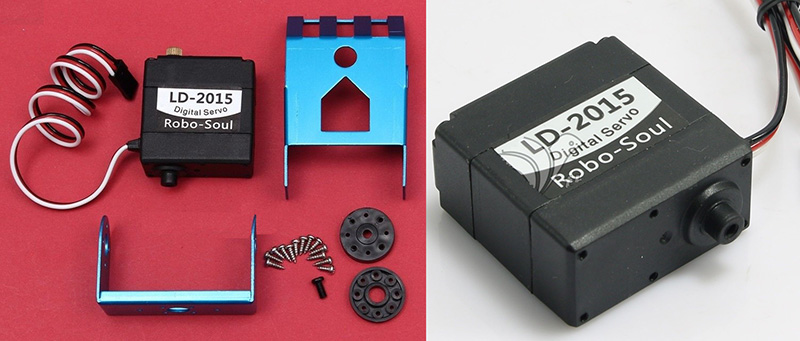
FIGURE 7.
It’s “wingless” (no mounting flanges) and has an integral axle opposite the output shaft for increased strength and less flexing.
Sail winch servos (720 degree servos) have different internal gearing which rotates the output shaft two full rotations, stopping at each extreme. Do not confuse these with “360 degree servos” — an alternative and unfortunate term for continuous rotation servos.
Linear servos are controlled by standard servo signals and come in different sizes — from the tiny Spektrum in Figure 8 to the giant Firgelli in Figure 9. EMS sells a $10 kit to convert a Futaba S3003 to linear, or you can buy the smaller VS-19 Pico linear servo for the same price.
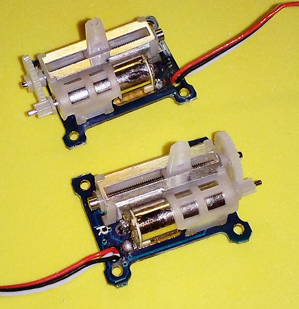
FIGURE 8.
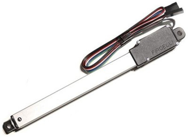
FIGURE 9.
Power servos are monstrous stump-pulling affairs. If power is your primary concern, ServoCity’s $240 SPG7950A-BM offers an astounding 3,402 ounce-inches of torque (Figure 10). It’s a 180 degree standard servo, also available in 360 degree and continuous rotation versions.
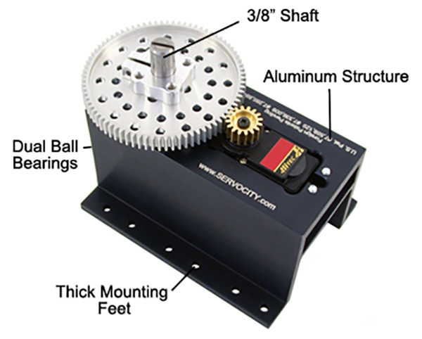
FIGURE 10.
WHERE TO BUY
Servos are widely available at local hobby shops and online. Standard size analog servos are generally priced from $5-$65. ServoCity mainly sells big brands like Futaba and Hitec, along with their wide variety of servo accessories. Discounter Hobby King sells all brands, including smaller Turnigy, BMS, and Tower Pro/Hextronic brands. Hobby King has an exceptional value in its $2.69, nine gram HXT900 version.
It is very popular and often on backorder. Hobby robotics sellers Adafruit, Parallax, Pololu, RobotShop, Solarbotics, and SparkFun all sell servos.
SERVO BATTERIES/POWER SUPPLIES
Not surprisingly, a servo’s power output gets stronger and faster as the supply voltage increases, but going much above 6V risks damage as mentioned earlier. Some servos can operate down to three or four volts with correspondingly lower power and speed, and often with less accuracy and repeatability. Some of my small robots use a single 3.7V Li-Ion battery to power everything directly, including their CR servos.
Some applications have very specific power requirements. A six-axis arm I built worked very well, but it required a very specific 4.0 volts for proper operation. The servos would oscillate at higher voltages and lost precision at lower voltages.
As mentioned initially, servos consume most of the power on a robot. I bench tested a dozen servos of various sizes and under ideal stationary, quiet, no-load conditions, they all draw 5-10 mA. Sounds very efficient. As soon as they “growl” (still stationary with no load applied), however, current jumps up to 80-100 mA just sitting there. Try slow motion with no load and it goes up to 100-150 mA. Any loads or just accelerating an unloaded servo can pull an amp or more per servo.
I have generally found that a single battery can power a robot’s servos and microcontroller if filter/decoupling caps are used. A small 0.1 µF disk cap and a 10+ µF electrolytic cap right at the microcontroller power pins works great. Of course, the battery needs to be able to maintain voltage while delivering high current.
Choosing the right battery and servo combination for a robot takes experience and testing. Rechargeable lithium-ion (Li-Ion) and lithium polymer (Li-Po) batteries offer better power to weight ratios than older NiMH or NiCad batteries, and make disposable alkaline cells look ridiculous in comparison. Perhaps the most common “noob” problems discussed in Parallax’s very helpful robotics forum stem from weak alkaline batteries. Things appear to function properly until the servos move — drawing an amp or more — causing the old batteries’ voltage to drop and reset the microcontroller. New alkaline batteries almost always solve the problem.
An outstanding example of servo power management is the walking "Tai Chi" robot (Figure 11) shown in the video and discussed at www.picaxeforum.co.uk/showthread.php?27524-9g-Tai-Chi-Stepper. The builder is running 12 small 9 g servos from just four AAA alkaline batteries.
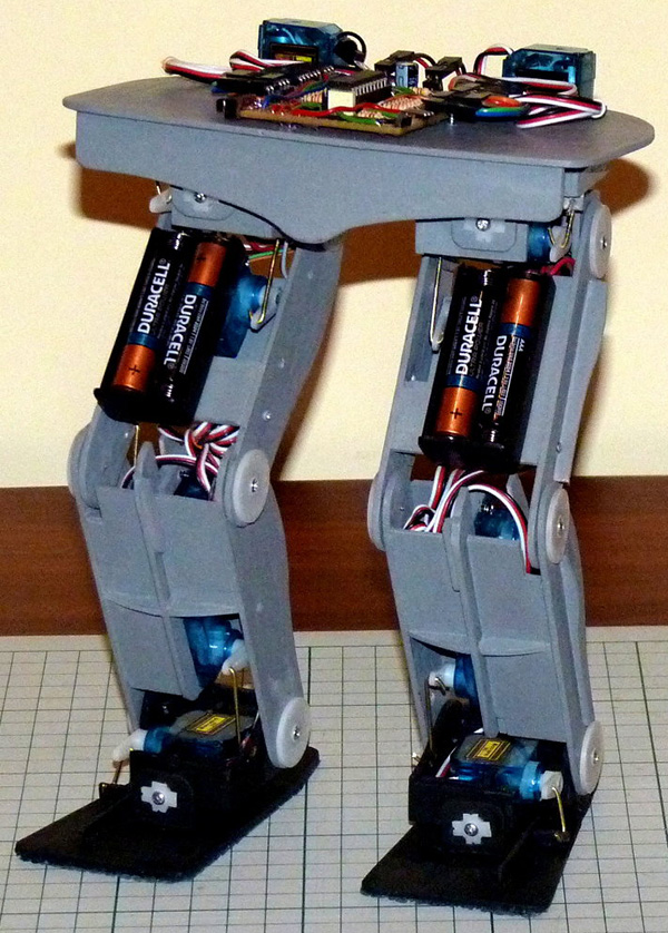
FIGURE 11.
Gorgeous new homemade 12-servo biped walker
CONTROLLING SERVOS FROM A MICROPROCESSOR
Hobbyists use several different microprocessors in their robots. Which one is “best” is a subject of spirited debate — we robo-geeks are just as passionate as sports fans. The BASIC Stamp 2 and PICAXE are easy for beginners to learn since they use the BASIC language.
Arduino is everywhere, and there are libraries and tutorials for its C-like language. Parallax’s Propeller does real multitasking on its eight cogs, and can be programmed in both C and its dedicated Spin language.
To keep this article of general interest, I’ve included four simple code snippets for comparison. These barebones programs generate signals to alternately “slam” a servo (no acceleration or ramping) between the 1,000 ms and 2,000 ms positions once each second.
Code Samples
Arduino: oscillate servo between positions 0 and 180 (approximate degrees)
#include <Servo.h>
Servo fred; // create servo object to
// control servo named “fred”
void setup()
{
fred.attach(9);
// attach servo “fred” on pin 9
// to the servo object
}
void loop()
{
fred.write(0);
// move servo to position 0
delay(1000);
// pause 1 second
fred.write(180);
// move servo to position 180
delay(1000);
// pause 1 second
}
PICAXE: code oscillates servo between positions 100 and 200 (1000-2000 ms pulse)
servo 1,100 ‘ initialize servo on pin 1 to center position 100
do ‘ start loop
servopos 1,100 ‘ move servo to position 100
pause 1000 ‘ pause 1 second
servopos 1,200 ‘ move servo to position 200
pause 1000 ‘ pause 1 second
loop ‘ end loop
BASIC Stamp 2
do
for b0=1 to 50
pulsout 1,1000
pause 20
next
for b0=1 to 50
pulsout 1,2000
pause 20
next
Propeller (Spin language)
CON
_clkmode = xtal1 + pll16x
‘ The clock frequency will be
‘ 16 times the crystal
‘ frequency.
_xinfreq = 5_000_000
‘ We are using a 5MHz crystal.
OBJ
Servo : “Servo32v7.spin”
‘ This object will start a cog
PUB ServoDemo
Servo.Start
‘ Start Servo Object
repeat
Servo.Set(16, 1000)
‘ Move Servo
waitcnt(clkfreq + cnt)
‘ wait one second
Servo.Set(16, 2000)
‘ Move Servo
waitcnt(clkfreq + cnt)
‘ wait one second
SUMMARY
I hope this article gave you a little clearer view of analog servos. They have been around for a long time and will be around a good while longer. In some ways, they are the unsophisticated “brutes” of the robotics world — the final gear-grinding, current-sucking, heat-generating “dumb” output component of an otherwise sophisticated high-tech robot. In the end, robots are all about controlled mechanical motion, and servos are what allow that magic to happen.
Thoroughly understanding servos’ strengths and limitations can help to identify which things are handled better in software vs. hardware. The availability and affordability of servos and microcontrollers makes robotics a hobby that can be enjoyed by everyone. SV
Watch these helpful online servo tutorials:
www.youtube.com/watch?v=v2jpnyKPH64
www.youtube.com/watch?v=iGS_kz8hx4k
Article Comments