Using Radio Control Servo Motors in Robotics
By Gordon McComb View In Digital Edition
Servo motors have earned an important place in robotics. Fortunately for robot builders, another hobby — model radio control — has made these motors plentiful, easy to use, and best of all, inexpensive.
In this article, you'll learn what you need to know to use radio control (R/C) servos in your robot projects. While there are other types of "servo" motors, it is the R/C type that is commonly available and affordable, so I'll be sticking with those only.
The Magic of R/C Servo Motors
Servo motors designed to be operated via a radio-controlled link in model airplanes and cars are commonly referred to as radio-controlled servos though, in fact, the servo motor itself is not what’s radio controlled. The motor is merely connected to a radio receiver on the model. The servo takes its signals from that receiver. This means you don’t need to control your robot via radio signals just to use an R/C servo (unless you want to, of course). You can control a servo with your PC, a microcontroller such as the Arduino, or even a simple timer circuit.
Figure 1 shows a typical standard-sized R/C servo motor.
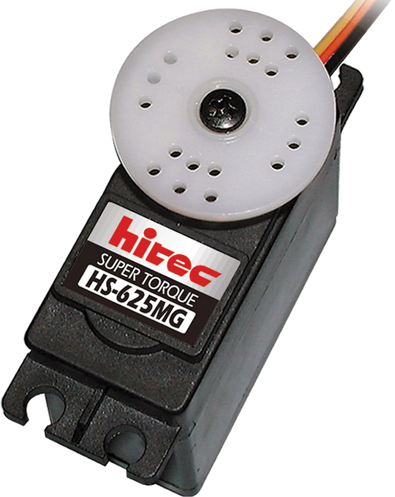
FIGURE 1. A standard size servo motor for radio controlled model airplanes and cars. The flanges allow easy mounting, and the output of the servo can be readily attached to wheels, linkages, and other mechanisms. Photo courtesty Hitec RCD.
It measures about 1-1/2” x 3/4” x by 1-3/8”. For this style of servo, its size and the way it’s mounted is the same, regardless of the manufacturer. That means you have your pick of a variety of makers and can compare prices. There are other common sizes of servo motors besides that shown in the figure which are used for specialty applications. These include model airplane landing gear mechanisms. I won’t be talking about these here, but just know they’re available should you want to experiment further.
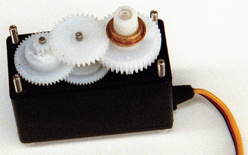
Inside the servo is a motor and various other components neatly packaged (see Figure 2).
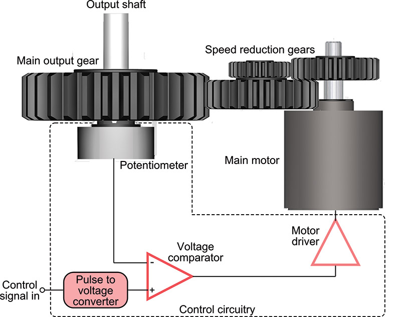
FIGURE 2. How an R/C servo works. A control signal causes the motor to turn one direction or the other, depending on the current position of the output shaft.
While not all servos are exactly alike, all have these three major parts: motor, reduction gear, and control circuitry.
- Motor. A DC motor capable of reversing direction is at the heart of the servo.
- Reduction gears. The high speed output of the motor is reduced by a gearing system. Many revolutions of the motor equal one revolution of the output gear and shaft of the servo. In most servos, the output gear turns no more than about 180 degrees in either direction, and is limited by mechanical stops.
- Control circuitry. The output gear is connected to a potentiometer — a common electronic device similar to the volume control on a radio. The potentiometer connects with a control circuit. The position of the potentiometer indicates the position of the output gear.
The motor and potentiometer are connected to a control board — all three of which form a closed feedback loop. While 180° (half a circle) may not sound like much, in actuality such control can be used to steer a robot, move legs up and down, rotate a sensor to scan the room, and more. The precise angular rotation of a servo in response to a specific digital signal has enormous uses in all fields of robotics. As you can surmise, standard radio control servo motors are designed for limited rotation rather than for continuous rotation, like a DC gear motor. There are servos that rotate continuously — and you can modify one to freely rotate (see later). This allows you to use a servo motor to drive your robot around a room.
Powering and Controlling an R/C Servo Motor
Most R/C servo motors are designed for operation at 4.8 to 6 volts. Some can be powered with up to 7.2 or even 9.6 volts, but these aren’t as common. In any case, you should always check the specifications of your servos before applying juice to them to make sure you are operating them within safe limits.
You can’t run an R/C servo simply by connecting it to a battery. It needs special control signals to operate. In a radio control application, the receiver — mounted some place in the airplane or vehicle — both powers and controls the servo. For robotics, you replace the function of the receiver with a microcontroller or other circuit. As it turns out, it’s not terribly hard to control a servo using simple programming. It’s easy stuff for all the popular microcontrollers, such as the Parallax BASIC Stamp and Propeller, the Arduino, and PICAXE.
The control signal that commands a servo to move to a specific point is in the form of a steady stream of pulses. The exact duration of the pulse — in fractions of a millisecond (thousandths of a second) — determines the position of the servo as shown in Figure 3.
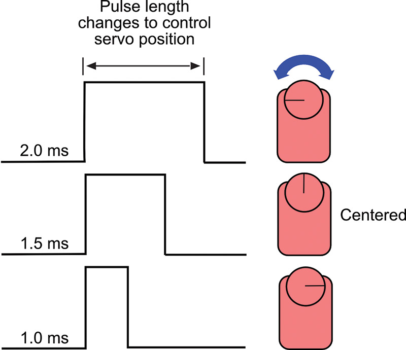
FIGURE 3. The length of the control pulses determines the angular position of the servo shaft. The pulse range is from 1.0 milliseconds to 2.0 ms. A pulse of 1.5 ms (1,500 µs) positions the servo shaft in the middle.
Note that it is not the number of pulses per second that controls the servo, but the duration of the pulses that matters. This is very important to fully understand how servos work, and how to control them with a microcontroller or other circuit. Specifically, the servo is set at its center point if the duration of the control pulse is 1.5 milliseconds. Durations longer or shorter command the servo to turn in one direction or the other.
- A duration of 1.0 milliseconds (ms) causes the servo to turn all the way in one direction.
- A duration of 2.0 ms causes the servo to turn all the way in the other direction.
- To recap, a duration of 1.5 ms causes the servo to return to its mid-point.
The servo needs about 30 to 50 of these pulses per second (refer to Figure 4.)

FIGURE 4. Control pulses are repeated ("refreshed") at roughly 50 Hz (50 times each second).
This is referred to as the refresh or frame rate; if the refresh rate is too low, the accuracy and holding power of the servo is reduced. If there are way too many pulses per second, the servo may jitter and fail to work properly.
The power delivered to the motor inside the servo is also proportional to the difference between where the output shaft is and where it’s supposed to be. If the servo has only a little way to move to its new location, then the motor is driven at a fairly low speed. This ensures that the motor doesn’t “overshoot” its intended position. If the servo has a long way to move to its new location, then it’s driven at full speed in order to get it there as fast as possible. As the output of the servo approaches its desired new position, the motor slows down. What seems like a complicated process actually happens in a very short period of time — the average servo can rotate 60° in a quarter to half second.
Most standard servos are designed to rotate back and forth by 90° to 180°, given the full range of timing pulses. You’ll find the majority of servos will be able to turn a full 180° or very nearly so.
The actual length of the pulses used to position a servo to its full left or right positions varies between servo brands, and sometimes even between different models by the same manufacturer. You need to do some experimenting to find the optimum pulse width ranges for the servos you use. This is just part of what makes robot experimenting so fun! The 1–2 ms range has built-in safety margins to prevent possible damage to the servo. Using this range provides only about 90° to 120° of turning, which is fine for many tasks.
If you want a full stop-to-stop rotation, you need to apply pulses shorter and longer than these. Exactly how long depends entirely on your specific servo. Full rotation (to the stop) for one given make and model of servo might be 0.730 milliseconds in one direction, and 2.45 milliseconds in the other direction.
You must be very careful when using shorter or longer pulses than the recommended 1–2 ms range. Should you attempt to command a servo beyond its mechanical limits, the output shaft of the motor will hit an internal stop which could cause gears to grind or chatter. If left this way for more than a few seconds, the gears may be permanently damaged.
The 1.5 millisecond “in-between” pulse may also not precisely center all makes and models of servos. Slight electrical differences even in servos of the same model may produce minute differences in the centering location. It’s not hard to adjust for these differences, but you need to know about them so you don’t get frustrated when you find the servo isn’t behaving the way you think it should!
Timing signals for R/C servos are often stated in milliseconds, but a more accurate unit of measure is the microsecond — or millionth of a second. To convert milliseconds to microseconds, just move the decimal point to the right three digits. For example, if a pulse is 0.840 milliseconds, move the decimal point over three digits and you have 0840, or 840 microseconds (lop off the leading zero; it’s not needed).
A Deeper Look at the Mechanical Guts of a Servo
The motor inside an R/C servo turns at several thousand RPMs. This is way too fast to be used directly, so all servos employ a gear train that reduces the output of the motor to the equivalent of about 50–100 RPM. Servo gears can be made of nylon, metal, or a proprietary material.
Besides the drive gears, the output shaft of the servo receives the most wear and tear. On the least expensive servos this shaft is supported by a plastic or resin bushing which obviously can wear out very quickly if the servo is used heavily. A bushing is a one piece sleeve or collar that supports the shaft against the casing of the servo.
Metal bushings — typically made from lubricant-impregnated brass (often referred to as Oilite, a trade name) — last longer but add to the cost of the servo.
The best — and more expensive — servos come equipped with ball bearings, which provide the longest life. Ball bearing “upgrades” are available for some servo models, but it’s usually cheaper (and certainly easier) just to buy a servo already equipped with them.
When looking at servos, you’ll often see a notion regarding the bearing type — either bushing or bearing — and whether it’s metal or plastic. You also may see a notation for “top” or “bottom;” this refers to the servo having a bushing or bearing on the top and/or bottom of the output gear like that shown in Figure 5.
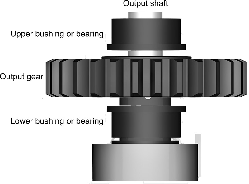
FIGURE 5. Ball bearings or bushings may be placed at the bottom and/or top of the servo output gear in order to prolong the life of the servo motor.
Better servos have two bushings or bearings: one each on the top and bottom of the gear. That provides the best support, and the servo will last longer.
Common Servo Specifications
Radio control servo motors enjoy some standardization. This sameness applies primarily to standardized servos, which measure approximately 1.6” x 0.8” x 1.4”. For other servo types, the size varies somewhat between makers, as these are designed for specialized tasks. Table 1 outlines typical specifications for several types of servos including dimensions, weight, torque, and transit time.
| Servo Type | Length | Width | Height | Weight | Torque | Transit Time |
|---|---|---|---|---|---|---|
| Standard | 1.6” | 0.8” | 1.4” | 1.3 oz | 42 oz-in | 0.23 sec/60° |
| 1/4-scale | 2.3” | 1.1” | 2.0” | 3.4 oz | 130 oz-in | 0.21 sec/60° |
| Mini | 0.85” | 0.4” | 0.8” | 0.3 oz | 15 oz-in | 0.11 sec/60° |
TABLE 1. Typical Servo Specifications.
Of course, except for the size of standard servos, these specifications can vary between brand and model. A couple of the terms used in the specs require extra discussion:
- The torque of the motor is the amount of force it exerts against a load. One common torque unit of measure for R/C servos is often expressed in oz-in (ounce-inches) — or the number of ounces the servo can lift when the weight is extended one inch from the shaft of the motor. (Other common measurements include Newton-meters but the general concept is all the same.) Servos exhibit high torque thanks to their internal gearing.
- The transit time is the approximate time it takes for the servo to rotate the shaft a certain number of degrees (usually 60°). Small servos turn at about a quarter of a second per 60°, while larger servos tend to be a bit slower. The faster the transit time, the faster acting the servo will be.
You can calculate equivalent RPM by multiplying the 60° transit time by six (to get full 360° rotation), then dividing the result into 60. For example, if a servo motor has a 60° transit time of 0.20 seconds, that’s one revolution in 1.2 seconds (.2 x 6 = 1.2), or 50 RPM (60 / 1.2 = 50).
Just know there are variations on the standard themes for all R/C servo classes. For example, standard servos are available in more expensive high speed and high torque versions. Servo manufacturers list the specifications for each model, so you can compare and make the best choice based on your particular needs.
Besides overall size, another common trait in R/C servos is the connector and even wire colors. There are three primary connector types found on R/C servos: “J” or Futaba style; “S” or Hitec/JR style; and “A” or Airtronics style.
Servos made by the principal servo manufacturers — Futaba, Airtronics, Hitec, and JR — employ the connector style popularized by that manufacturer. In addition, servos made by competing manufacturers are usually available in a variety of connector styles, and connector adapters are always available. For robotics, the physical shape of the connector is often not an issue as the connector is used with a simple three-pin header to make electrical contact. The pin spacing is the standard .100”; where the connector type comes into play is when using an R/C receiver designed for one servo type or another.
The pinouts of the three wires used with servos is the same, except for the “old-style” Airtronics servos (and the occasional oddball four-wire servo). This pinout is shown in Figure 6.
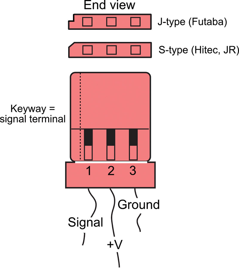
FIGURE 6. Standard three-pin connector used on the vast majority of R/C servo motors. The connector may or may not be "keyed" using a groove or notch.
With very few exceptions, R/C servo connectors use three wires providing ground, DC power (+V), and signal. The +V DC power pin is almost always in the center; that way, if you manage to plug the servo in backwards, there’s less chance of damage caused by reverse polarity.
Most servos use color coding to indicate the function of each connection wire, but the actual colors used for the wires vary between servo makers. Here’s a general idea of what you’ll find on most servos out there:
- White, orange, or yellow: Signal.
- Red: +V (DC power).
- Black or brown: Ground.
Electronics for Controlling a Servo
Unlike a DC motor — which runs if you simply attach a battery to it — a servo motor requires a particular type of control signal to manage its direction. All microcontrollers can be used to control an R/C servo. The basic connection scheme is shown in Figure 7.
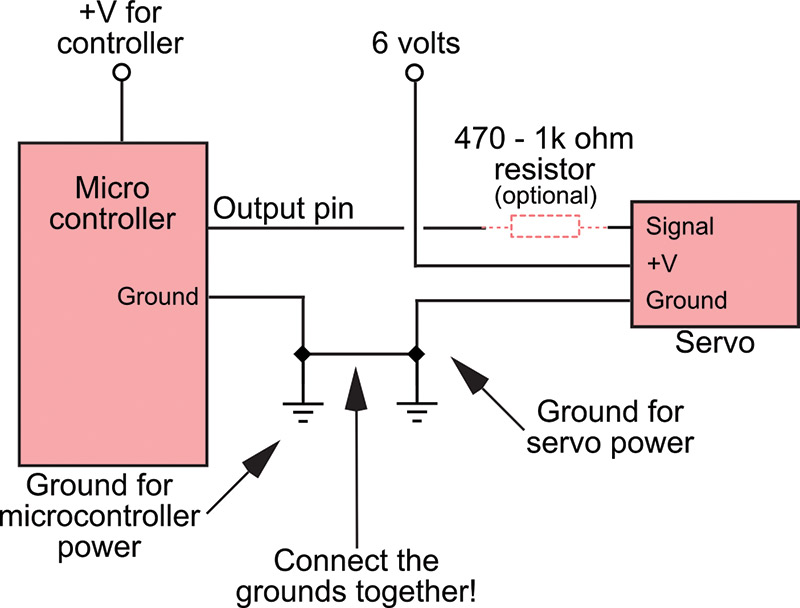
FIGURE 7. General connection diagram for attaching a microcontroller to a servo motor. The resistor is optional, but is included to prevent excessive current draw by the servo.
- The microcontroller and servo can share the same power source, assuming the controller has an onboard regulator. However, it’s much better to use a separate source for the servo. Why? Servos draw a lot of current when they’re first turned on or in motion. By using separate sources — a nine volt battery for the controller, for example, and a set of four AA cells for the servo — you avoid messy power line problems.
- When using separate power sources, be sure to connect the grounds from these sources together. Otherwise, your servo will not work properly.
- Only one input/output (I/O) line from a microcontroller is needed to operate the servo. You may insert an optional resistor in-line between the controller and the signal input of the servo. This helps protect the microcontroller in case the servo has an (unlikely) internal electrical problem.
Even if your microcontroller isn’t a speed demon and has no trouble creating pulses for up to six or eight servos, you may not want to use it for that task, freeing precious processing time for other robot functions. When using many servos, you can turn to a dedicated servo controller. These are separate circuit boards that act as a pulse making coprocessor. Making the electrical connection to your servos is often as simple as plugging a set of three-pin headers into a solderless breadboard. Figure 8 shows attaching two servos to an Arduino Uno microcontroller board.
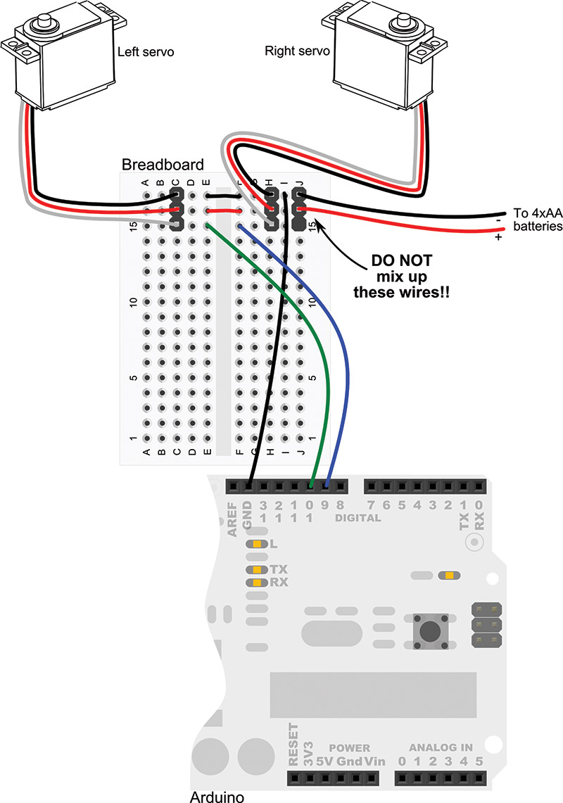
FIGURE 8. You can use a solderless breadboard to connect multiple servos to a microcontroller such as the Arduino Uno.
Note that the servos are powered by their own set of batteries, and that the negative (ground) connection of these batteries is shared with the Arduino ground connection. This is important, or otherwise the servos are likely to behave erratically — if they operate at all.
You can make servo plug adapters for a solderless breadboard using the so-called “double long” male pin headers available at Parallax, Pololu, and other online sources. These are like standard male pin headers, except the pins are equally long on both ends (see Figure 9). This allows for plugging the pins into both a solderless breadboard and the servo connector.
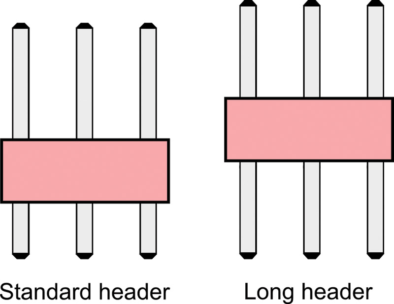
FIGURE 9. Use double-length male headers with standard .100" spacing between pins to connect R/C servos to your circuits. Get the kind where you can break off as many of the pins as you need.
Using Continuously Rotating Servos
So far, I’ve only talked about servos that are used when precise angular positioning is required — like scanning a sensor from side to side. Fortunately, R/C servos can also rotate continuously, either by design or via modification that you perform yourself. R/C servos make terrific drive motors for your robot. They tend to be less expensive than comparable DC gearmotors of the same specification, and they come with their own driver electronics. They’re definitely worth considering for your next robot. Servos that rotate continuously act like an ordinary geared DC motor, except it’s still controlled by sending it pulses.
- To make the motor go in one direction, send it 1.0 ms pulses.
- To make the motor go in the other direction, send it 2.0 ms pulses.
- To make the motor slow to a stop, send it 1.5 ms pulses.
- To make the motor stop altogether, stop sending it pulses.
Note that stopping the motor by ceasing the pulses works for most servos except for digital servos. On most digital servos, when pulses are stopped the servo will merely continue with the last good position information it received. You’re not likely to use digital servos for continuous rotation, so this problem seldom comes up in real life, but keep it in mind just in case.
There is a small handful of servos made for continuous rotation. These include the GWS S-35, the Parallax continuous rotation servo, and the SpringRC SM-S4303R. These are available from a variety of online resellers such as Pololu, Parallax, and SparkFun.
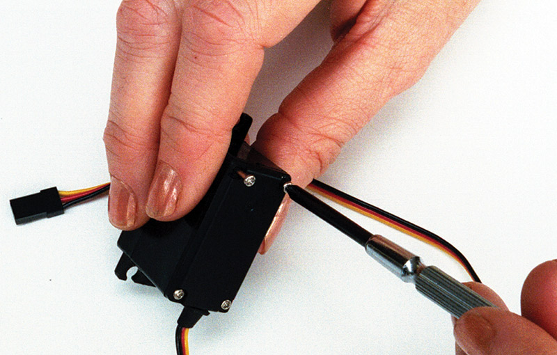
You can also convert most any servo to continuous rotation. Once modified, they are no longer capable of precise angular rotation, but they’re perfectly suited as drive motors for wheeled and tracked bots. There are a number of methods you can use to modify an R/C servo for continuous rotation. The basic process involves removing the mechanical stops, and — for some types of servo surgery — making a change in the electrical connections inside. You’ll need the following tools to complete the conversion process:
- #0 or #00 Phillips screwdriver
- 1/8” or smaller flat-bladed screwdriver
- “Nippy” cutters, X-ACTO™ blade, or razor saw
- Small flat jeweler’s file
Servo modification varies somewhat between makes and models, but the basic steps are similar. The procedure discussed here is common to those servos where the output gear does not require to be physically mounted on the potentiometer shaft. Rather, the gear sits atop a ball bearing or a plastic or metal bushing.
Note! It’s possible to damage the servo and/or its main output gear, so have a spare servo handy in case you make a mistake. This is a learning process and requires some patience and skill to get right.
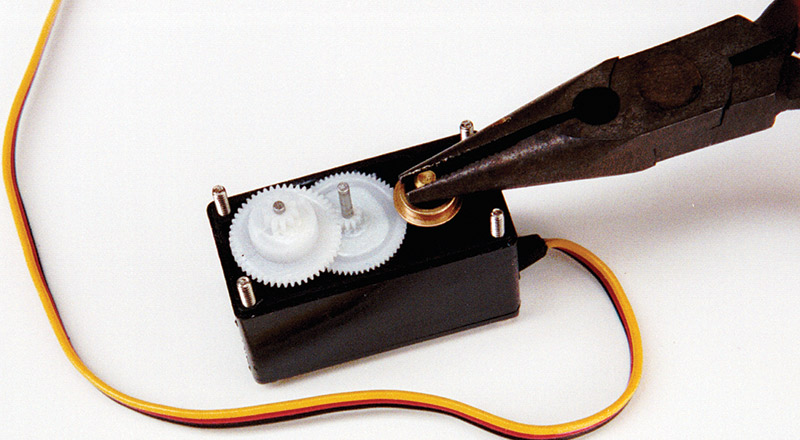
1. Remove the case of the servo to expose the gear train, motor, and potentiometer. This is accomplished by removing the four screws on the back of the servo case and separating the top and bottom.
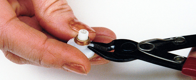
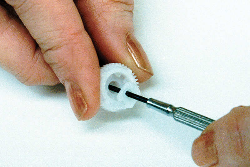
2. File or cut off the nub on the underside of the output gear that prevents full rotation. This typically means removing one or more gears, so you should be careful not to misplace any parts. If necessary, make a drawing of the gear layout so you can replace things in their proper location, or take a photo. Important! When cutting off the nub, you’ll want to “nibble” it away in smaller chunks. The pressure of a single large cut may cause too much pressure in the plastic, breaking the gear.
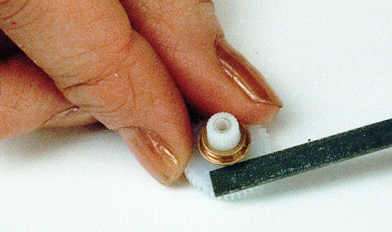
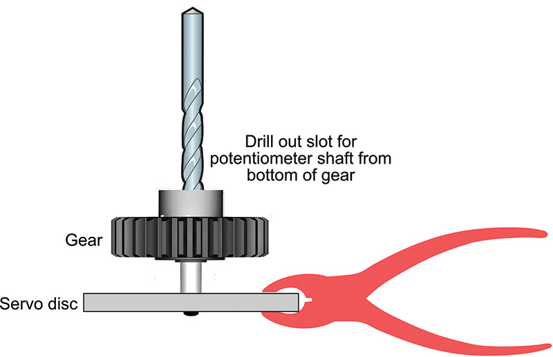
3. On those servos that have a retainer clip at the bottom of the output gear, remove the clip to disengage the potentiometer from the gear. In this way, the pot no longer turns when the gear does. On some servos, there is no retainer clip; the servo engages into a spline molded into the bottom of the gear. On these, you need to carefully drill out the bottom of the gear. One method is to temporarily attach the output gear to a large servo horn disc, and clamp the gear and horn steady with a pair of pliers.
4. Connect the servo to a microcontroller and apply 1.5 ms pulses to it. Carefully adjust the potentiometer until the servo stops.
5. Reassemble the case.
Of course, I could go on for many more pages talking about radio control servos for robotics, but we’re out of space. For a hands-on look, check out my ArdBot and ArdBot II series in past issues of SERVO Magazine.
The original ArdBot appeared starting back in the November 2010 issue; the updated ArdBot II appeared beginning in October 2013.
In both of these series, you’ll see how to build a small Arduino-based desktop robot that uses twin R/C servo motors for locomotion. SV
Analog Versus Digital Servos
The most common — and most affordable — R/C servos are analog, meaning their control circuitry uses traditional techniques for controlling the motor. Digital servos use onboard microcontrollers to enhance their operation.
Among the added features of digital servos are higher power and programmable behavior. With the proper external programmer (available separately at extra cost), it's possible to control the maximum speed of the servo, for example, or make the servo always start from power-up in a specific position.
Except for higher torques, from an applications standpoint there is little difference between analog and digital servos. You control both the same way. However, the higher torque of a digital servo means the motor is drawing more current from its power source, which means batteries tend not to last as long between charges.
For most robotics applications, digital servos are not required. You can get by with the less expensive standard analog servos. An exception is when building a walking robot, where the extra torque of digital servos comes in handy. Six-legged walking bots may use 12 or even 18 servos just for the legs. The higher torque helps to offset the added weight of all those servos.
Article Comments