Build a Bluetooth Controlled Tank
By Luis Martinez, Matt Hales View In Digital Edition
As kids, many of us can remember being captivated by new toys on TV like off-road RC cars or stomp rockets. One particularly prominent toy in our lives was Nerf™ guns: a line of devices which were an ostentatious and often oversized analog to BB-guns that shoot foam darts at higher-than-expected speeds. Inspired by our childish desire to combine something small and mobile with an overpowered toy, we built a Bluetooth controlled tank outfitted with a modified Nerf gun which can be controlled through software.
The user can move the tank forward and backwards, as well as turn in place in either direction through an app which features an intuitive D-pad configuration. Additionally, there’s a button available in the app to trigger the “cannon” to fire a dart that is manually loaded into the back.
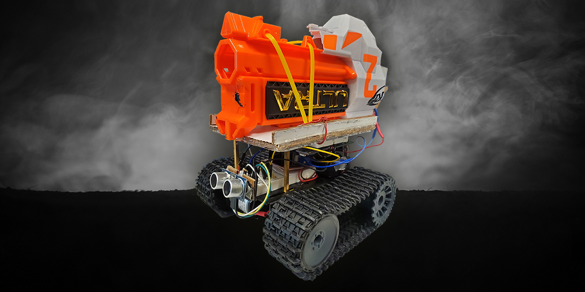
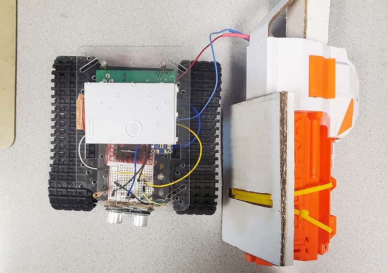
As seen in Figure 1, there’s also an ultrasonic distance sensor whose function is to prevent the user from ramming into walls or other objects.
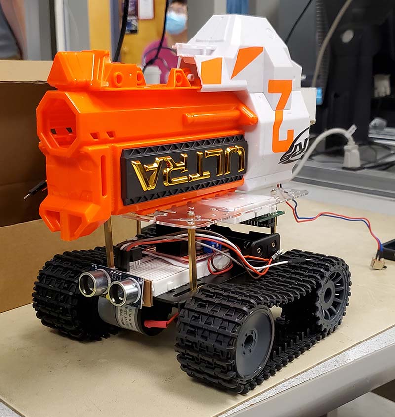
Figure 1 - The assembled project.
If the user drives too close to something, the software will prevent the user from moving forward or turning until it’s at a safe distance. This is by no means a discreet machine. The tank treads can be heard from another room and when the cannon fires up, it resembles a small war machine. However, we think these attributes contribute to the character and comedic attraction of the project.
System Overview
The tank can be broken into a few subsystems which make the whole project easier to think about: sensing, the motors, communication, the gun, and the power system. Each subsystem is — directly or indirectly — tied to a PIC32 microcontroller.
A high-level schematic of the electronics is shown in Figure 2.
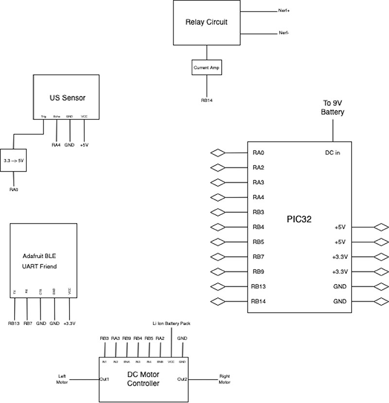
Figure 2 - System schematic.
The overall flow of information and control goes as follows: Someone presses a button in the phone app and the information about what button was pressed is sent over Bluetooth to the module. The Bluetooth module then relays that information to the microcontroller. From this, we can decide what outputs to send to the motor controller (or the Nerf gun) which would move them in the direction specified by the user.
In parallel to all of this, the microcontroller also receives distance information from the ultrasonic sensor. If it detects that we’re too close to an object, it stops the motors and overrides everything except a backwards command from the user. Figure 3 illustrates this process flow in a diagram.
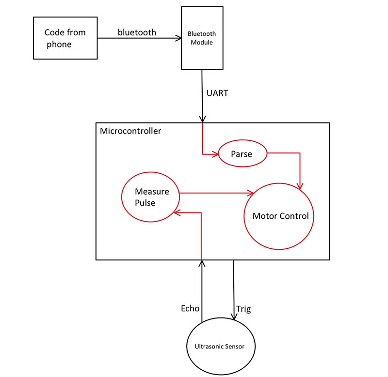
Figure 3 - Control flow diagram.
One important point to make about the software is that we used a multithreading library called Protothreads (created by Adam Dunkels) to allow us to communicate over Bluetooth and do distance sensing at the same time.
Note that, in reality, these are not happening at the same time. The switching between processes is fast enough compared to the physics of the robot or the rate at which the button can be pressed that it appears as if they operate in parallel.
Sensing
The ultrasonic sensor is a standard module found in virtually all Arduino starter kits. It takes up two GPIO pins and takes 5V to operate. This is an important detail, as while the ultrasonic sensor uses 5V logic, the microcontroller uses 3.3V logic. Therefore, we needed a couple circuits to make sure any signal sent from the microcontroller to the ultrasonic sensor gets bumped to 5V, and any signal sent from the ultrasonic sensor to the microcontroller gets stepped down to a 3.3V scale.
The ultrasonic sensor contains two data pins: a trigger pin which is an input; and an echo pin which is an output. Figure 4 illustrates the standard pinout.
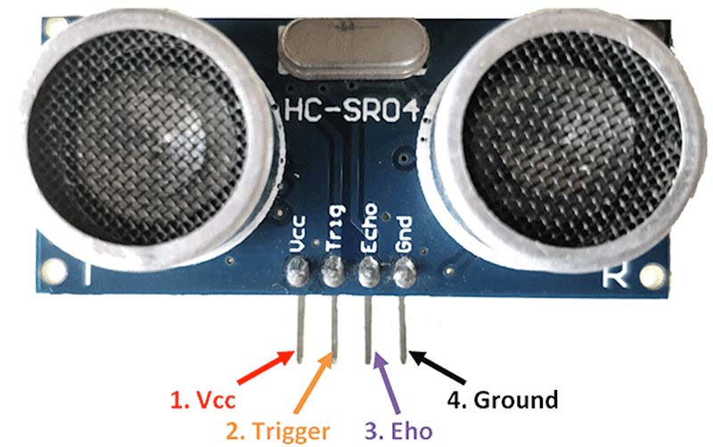
Figure 4 - Ultrasonic sensor pinout.
The trigger pin is used to tell the ultrasonic sensor when to take a new distance reading. The echo pin is an output to the microcontroller and contains information about the obtained distance measurement.
For the line going from the echo pin to the microcontroller, we can use a simple voltage divider to convert the 5V scale to a 3.3V scale. Some values that we chose were 1K and 2.2K. For the line going from the trigger pin to the microcontroller, we implemented a logic-level converter using a BJT (bipolar junction transistor; shown in Figure 5).

Figure 5 - Logic level converter.
When the signal from the microcontroller is low, the voltage drop from the base to the emitter is 3.3V, and the transistor is on so the output at the collector is 0V. When the signal from the microcontroller is high, the voltage drop from the base to the emitter is 0V, so the transistor is off, and the collector sits at roughly 5V.
The ultrasonic sensor thread operates according to the recommendations specified in the datasheet. Namely, we pull the trigger line high for at least 10 µs to tell the sensor to take a measurement. This happens every 70 ms to prevent overlap between the trigger signal and the response on the echo pin. The response from the sensor on the echo pin produces a square pulse whose width is proportional to the detected distance from an object.
Therefore, we need to measure the width somehow to retrieve the desired parameter. An intuitive way to do this — which is what we implemented — is to start a hardware timer on the rising edge of the echo pulse and stop it on the falling edge. The edges of the pulse are detected using hardware interrupts tied to the appropriate GPIO pin.
The ISR is configured to trigger on both the rising and falling edge of a digital input. On the rising edge, we initialize a 16-bit hardware timer running at 5 MHz that overflows every 65535 cycles to 0 and start it. On the falling edge, we record the value of the timer. This way, the pulse width in seconds can be calculated as (timer value) / (timer frequency). The distance, then, is calculated inside the ultrasonic sensor thread according to the formula:
Distance = (pulse width)*(speed of sound in air)*50
where distance is in meters, pulse width is in seconds, and the speed of sound in air is approximately 340 m/s.
Motor Control
To help control the direction and speed of the motors, a standard H-bridge/motor driver was added, where a PWM signal’s duty cycle (coming from the microcontroller to the ENA and ENB pins) sets the speed. A combination of control signals designates the direction of rotation. If IN1 is high and IN2 is low, then the motor rotates one way; if IN1 is low and IN2 is high, the motor rotates the other direction. If both IN1 and IN2 are high or low, there is no rotation.
The other motor channel is operated with pins IN3 and IN4. For example, take the configuration in Figure 6 with one motor connected to the motor controller driven by ENA and the IN1/IN2 pins.
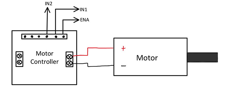
Figure 6 - Motor controller example.
The above configuration will yield the truth table, assuming the ENA and ENB pins are constantly outputting a nonzero duty cycle.
| IN1 | IN2 | Result |
| H | H | Motor does not turn. |
| H | L | Motor turns clockwise. |
| L | H | Motor turns counterclockwise. |
| L | L | Motor does not turn. |
Truth table.
For PWM generation, two wires are fed into the motor controller to delegate how fast the motors are spinning according to a duty cycle specification. For this, we used two output compare peripherals. Their job is to monitor the value of an incrementing timer and compare its value to a value specified by the user.
When the two match, a pin is pulled high, and is not pulled low until another match with a different value specified by the user is seen by the output compare module.
From this, we can see that by adjusting the values being compared to the incrementing timer, the duty cycle of the output waveforms can also be adjusted.
Communication
The Bluetooth module that we used is the Adafruit Bluefruit LE UART Friend which, as the name suggests, communicates with the microcontroller using the UART serial protocol. The only way to send information to this device in any straightforward way is through a phone or computer app that Adafruit developed.
As mentioned previously, the purpose of the Bluetooth module is to allow for untethered control of the tank using a computer or phone. The Adafruit BLE UART Friend module interacts specifically with the app Adafruit developed. The interface inside the app to control the tank is shown in Figure 7.
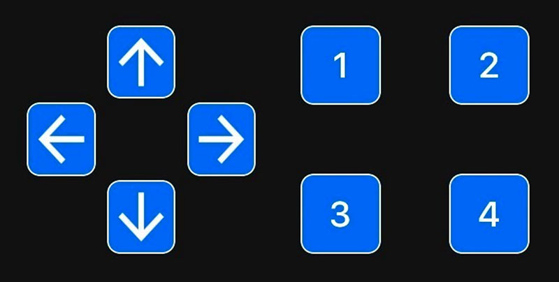
Figure 7 - D-pad used to control the tank.
Information moves through the system as follows: A button is pressed in the phone app which sends a code over Bluetooth to the Bluetooth module. The module then relays the information to the microcontroller.
When a button is pressed in the app interface, the string of characters that is sent from the device to the Bluetooth module is always prefixed by a ‘!’ character and suffixed by either a ‘0’ (button released) or a ‘1’ (button depressed). The remaining elements of the code specify what button was pressed. Some example codes are listed in Figure 8.
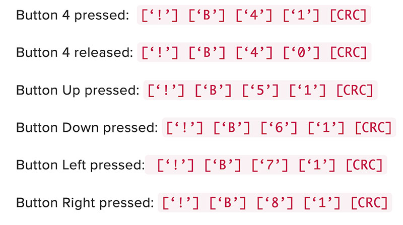
Figure 8 - Example button codes.
Now that the Bluetooth module has the code, there still remains the issue of relaying it to the microcontroller and acting upon it. For this, we created another thread which uses DMA (Direct Memory Access) to get data from the UART channel.
Physically, DMA is a small co-processor whose only job is to move memory from one location in the microcontroller to another independently of the CPU. In this case, DMA was employed at the beginning of the thread to transfer the character array in the UART receive buffer from the Bluetooth module to a place in memory specified by a globally defined character array in the C program.
The control flow of this operation is shown in Figure 9.
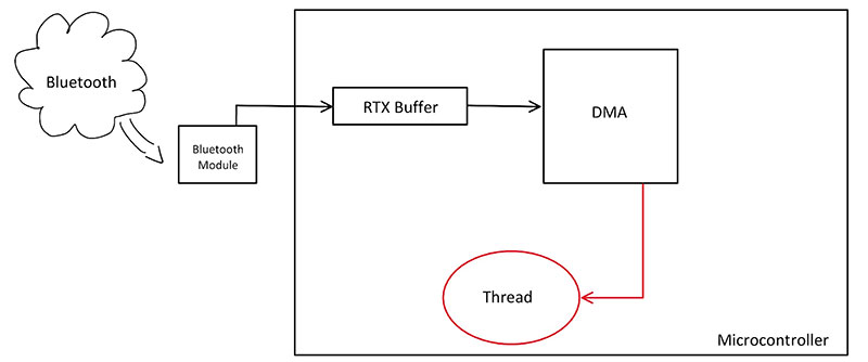
Figure 9 - DMA for Bluetooth module interaction.
If the first element of the character array starts with !, then we can proceed to call a function which takes action by setting certain pins on the motor controller or turning on the motors in the Nerf gun based on the rest of the string. Otherwise, the loop of the thread will start over.
The Gun
The mechanism for shooting the dart is a partially deconstructed motorized Nerf weapon. We sawed off the back half to gain easy access to the chamber where darts are inserted and the wires are connected to the motors. Originally, these wires were hooked up to a switch activated by the trigger which electrically connected the wires when pressed, causing the motors to turn on.
To allow the microcontroller to command when the motors are activated, we put together a simple relay circuit (shown in Figure 10) which, when sent a logical 1, completed the circuit between the two Nerf gun wires.
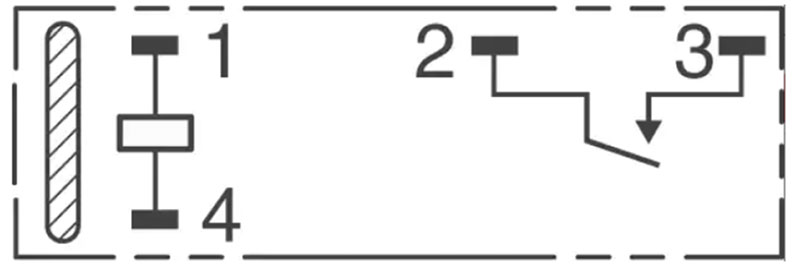
Figure 10 - Electric relay schematic.
When testing the relay switch for firing the Nerf dart using an external power supply, the relay switch functioned perfectly. However, the microcontroller’s GPIO pins could not generate sufficient current to close the relay switch’s coil.
As a result, a current amplification circuit was needed to boost the current from the serial pin to the relay switch. The schematic in Figure 11 shows how the circuit is constructed.
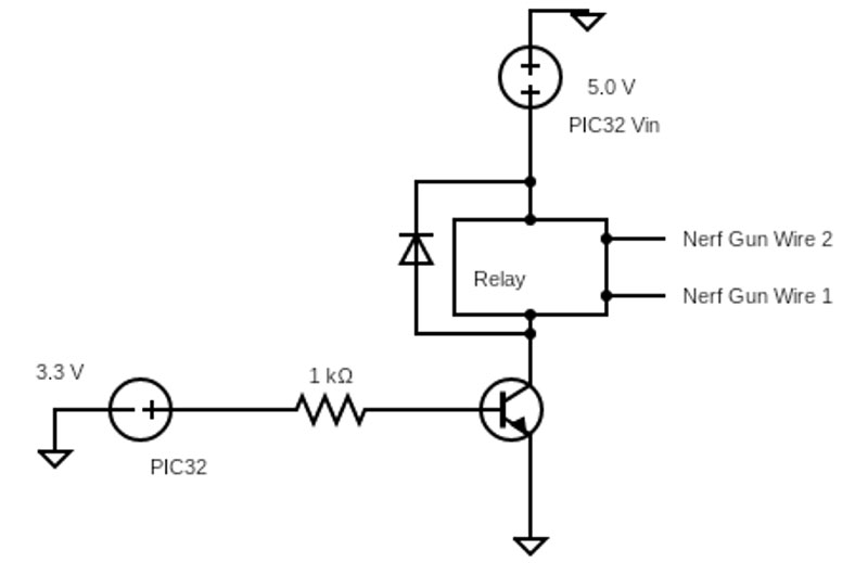
Figure 11 - Schematic of current amplifier circuit with relay.
Figure 10 illustrates how pins 1 and 4 are connected via an induction coil, where pins 2 and 3 are connected when the latch between them closes.
Like the tank motors, the decision for whether the relay is on or off is determined by pressing a button in the Bluetooth app.
The Power System
For powering the robot, we had three separate battery systems included: a 9V battery for the microcontroller; two 18610 lithium-ion batteries for the tank motors; and six AA batteries for the Nerf gun’s barrel motors. When powering the PIC32 with the 9V battery, we used a 9V to DC power adapter that plugged into the onboard power connector.
While the system only needs 5V to run, this setup ensured that the system would have enough power to run for a long period of time while disconnected from an electrical outlet. Figure 12 shows a schematic of the PIC32 with the 9V battery connector.
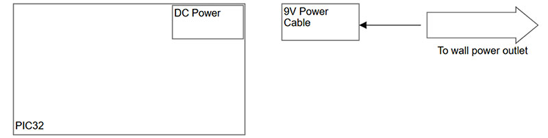
Figure 12 - PIC32 power system.
To power the motors of the tank, the lithium-ion batteries were connected to the H-bridge using a battery pack housing and the included wires. This gave a secure way of holding the batteries to the tank and an easy way to wire the batteries. The schematic in Figure 13 shows how the batteries for the tank motors were connected.
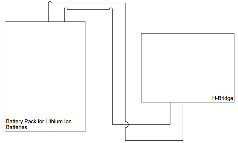
Figure 13 - Power system for the tank motors.
Lastly, for the Nerf gun’s motors, these were hidden in a compartment inside the battery of the gun. By removing a screw and sliding off the cover, we could insert six AA batteries into the system.
This system was only integrated with the Nerf gun’s motors, so it only powered the motors of the gun. Figure 14 is a schematic of this power system.
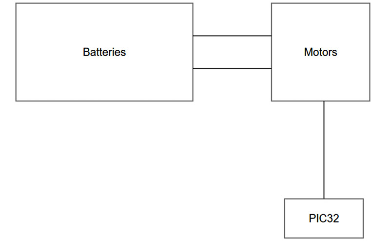
Figure 14 - Nerf gun’s power system.
Results
The final product was a complete remote control tank that could roam the floor of the lab and fire a Nerf dart on command. Thanks to the Bluetooth module we used, the integrated D-Pad and mappable buttons allowed for wireless control of the tank in all directions, as well as the ability to shoot a foam bullet on the press of a button which was mapped to button 1.
Top-down shot of the tank with the Nerf gun barrel removed from the platform.
When the tank ventured too close to a wall, our ultrasonic sensor would detect the distance and stop the robot, only permitting the user to reverse the tank until it was far enough away that it would not collide with any obstacle in front.
We did, however, encounter some limitations in the hardware that should be considered if anyone wants to build a similar device. One major restriction came with the ultrasonic sensor as it would behave unpredictably when placed in spaces where it’s not rated to measure. In our case, this was beyond a radius of four meters from the robot.
Therefore, we found it best to use the robot in a well-defined area that obeys the constraints of the ultrasonic sensor’s specifications.
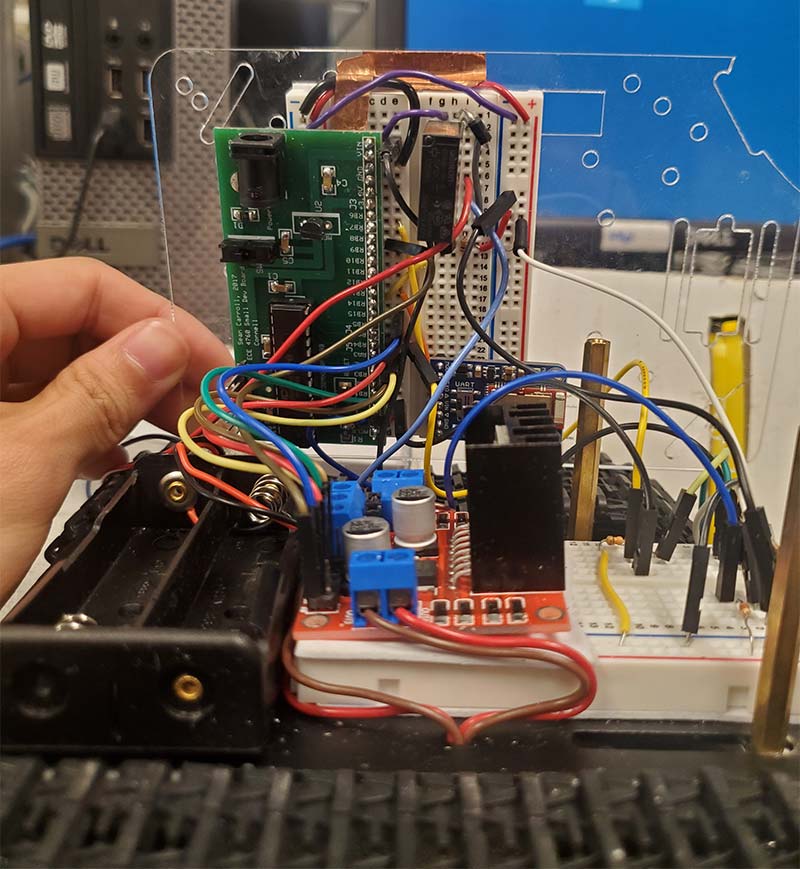
Electronics underneath the top platform
Another limitation we encountered was with the inability to create custom software for the Bluetooth module. The unit we used didn’t allow for custom software integrations, and our attempts to create custom Python GUIs that connected to the module from a PC to achieve an increase in functionality were met with roadblocks that would waste more time solving than circumventing.
The use of another Bluetooth module that allowed for custom software would solve this issue. SV
A special thank you to Chris Kosteini for his contributions to this article.
Link to Our Final Project
Parts List
✓ Tank Chassis x1
✓ Tank Motors x2
✓ Adafruit Bluefruit LE UART Friend x1
✓ Nerf Gun x1
✓ Ultrasonic Sensor x1
✓ Lithium-Ion Batteries x3
✓ H-Bridge Motor Controller x1
✓ Relay x1
✓ 9V Battery x1
✓ PIC32 Microcontroller x1
✓ 1K Resistor x3
✓ Diode x1
✓ BJT x2
✓ Wires As needed
Parts Links
- https://www.amazon.com/Professional-Chassis-Tracked-Platform-Raspberry/dp/B08WXB72PR/ref=sr_1_16?dchild=1&keywords=tank+chassis+and+motors&qid=1634774079&sr=8-16
- https://www.adafruit.com/product/2479
- https://www.amazon.com/gp/product/B07RWMNV67/ref=crt_ewc_title_oth_1?ie=UTF8&psc=1&smid=ATVPDKIKX0DER
- https://www.amazon.com/Pcs-MCIGICM-Points-Solderless-Breadboard/dp/B07PCJP9DY/ref=sr_1_4?crid=15NGSXLWQ8J76&dchild=1&keywords=breadboard&qid=1634486786&sr=8-4
- https://www.sparkfun.com/products/15569
- https://www.amazon.com/gp/product/B08GH7RLD1/ref=ppx_yo_dt_b_asin_title_o07_s00?ie=UTF8&psc=1
- https://www.amazon.com/gp/product/B014KMHSW6/ref=ppx_yo_dt_b_asin_title_o07_s00?ie=UTF8&psc=1
- https://www.digikey.com/en/products/detail/omron-electronics-inc-emc-div/G5NB-1A-E-DC5/1731471
References
- https://learn.adafruit.com/introducing-the-adafruit-bluefruit-le-uart-friend/downloads
- https://www.build-electronic-circuits.com/h-bridge/
- https://learn.adafruit.com/bluefruit-le-connect/controller
- https://people.ece.cornell.edu/land/courses/ece4760/PIC32/index_UART.html
- http://ww1.microchip.com/downloads/en/DeviceDoc/32bitPeripheralLibraryGuide.pdf
- https://people.ece.cornell.edu/land/courses/ece4760/PIC32/index_Ref_Man.html
- https://components101.com/sensors/ultrasonic-sensor-working-pinout-datasheet
Article Comments