RobotBASIC Robots for Beginners — Part 1
By John Blankenship View In Digital Edition
SERVO readers that have never built a robot can be put off by the cost of even an entry-level chassis, and often find the low-level programming needed to control motors and interrogate sensors intimidating. This article shows options to make building your first robot a little easier.
If you have read RobotBASIC articles in the past, you might have assumed that RobotBASIC was either a simulation-only language or one used to create relatively complex robots (like the RB-9 in Figure 1 or Arlo in Figure 2). Both of these robots — as well as numerous simulations — have been discussed in previous SERVO articles.
![]()
FIGURE 1.
![]()
FIGURE 2.
The RB-9 is small, but it has an electronic compass, five ranging sensors, three line sensors, wheel encoders, a beacon detector, and battery monitoring (far more than many hobby robots). Arlo has the same features plus arms, voice recognition, speech, and more. Both of these robots can execute most programs written for RobotBASIC’s integrated simulator which can be used to speed the application development process.
While numerous sensors on both of these robots make it easy to experiment with a wide variety of situations and environments, generally they are too complicated for those new to robotics. Even beginner bots have challenges that can be difficult for novices.
Consider a robot with two drive wheels powered by DC motors. Proper motion control can require writing code that produces pulse-width modulation (PWM) to control speed; ideally, the speed will ramp up slowly to prevent jerky starts. Furthermore, all of this control must be properly timed between the two motors to ensure the robot can travel in a straight line and make turns as expected. Seasoned hobbyists often take such actions for granted, but writing these programs can be very intimidating for beginners.
Fortunately, there is an easy way for beginners to get started. A special chip containing the RobotBASIC Robot Operating System (RROS) is available from www.RobotBASIC.org (where you can also download a free copy of RobotBASIC). The chip provides the low-level code for controlling both DC and analog servomotors, and for interfacing with a variety of sensors. The chip allows robot builders to concentrate on high-level behaviors rather than worrying about low-level details.
Let’s see how the chip can simplify building a beginner bot.
Physical Construction
Before we get to the electronics, let’s look at the physical construction aspects of a small robot. For large or complex robots, purchasing a chassis — complete with motors — is often an excellent option. If this is your first robot, though, building your own can be fun and greatly lower your costs. Eventually, most people will want something sturdier and more powerful, but it makes sense for most beginners to minimize costs until they get some experience. For that reason, let’s build the cheapest robot chassis ever.
The size and shape of your chassis will be determined by your motors. Figure 3 shows two great options for a first robot. On the right, are DC motors and wheels that are readily available on eBay for only a few dollars. The motors on the left are continuous rotation servomotors from Parallax. Generally, the hardware and software needed to control DC and servomotors is totally different, but RobotBASIC’s RROS chip can control either type using the same instructions.
![]()
FIGURE 3.
Once you have chosen your motors, work can begin on the chassis. If you have the proper tools and skills, you could use plastic, wood, or metal, but foam board (available at most craft stores) can be easily cut with an X-ACTO® knife or razor blade, and it can create an excellent base for small robots. Figure 4 shows how easily bases can be cut for both the DC and servomotors shown in Figure 3.
![]()
FIGURE 4.
Once the base plates have been cut, the motors can easily be attached with hot glue as shown in Figure 5.
![]()
FIGURE 5.
Such mounting is far stronger than you might imagine (especially if you glue one or two wood strips around the edges of the motors as shown), yet the motors can be removed to be used in future projects.
You can also see in the figure how to build a simple “caster” which is needed on two-wheeled robots. It was made from a short piece of wooden dowel tipped with a chair leg slide (shown in Figure 6), but a block of foam board could easily substitute for the dowel.
![]()
FIGURE 6.
The Electronics
With the motors mounted, we can turn to the electronics, which are built on a solderless breadboard. Figure 7 shows small strips of wood glued to the top of the DC robot chassis.
![]()
FIGURE 7.
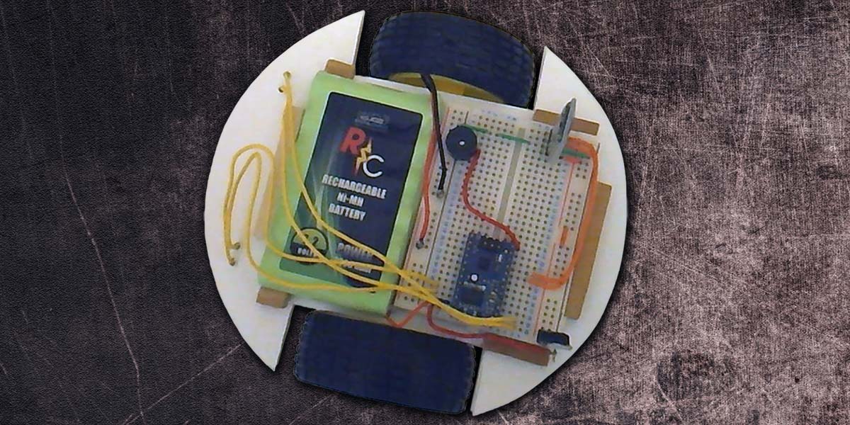
Figure 8 shows how these blocks hold the battery and breadboard in place.
![]()
FIGURE 8.
Figure 9 shows the schematic for the physical circuit built on the breadboard.
![]()
FIGURE 9.
Notice how few components are required. The two DC motors can connect directly to the RROS chip because it contains the necessary H-bridge circuitry for driving motors, as well as the low-level code for controlling them.
A Bluetooth transceiver provides the communication link to the PC running RobotBASIC. A regulator provides the five volt power needed for the transceiver and for other devices to be added later. The buzzer is not required, but having audible feedback when the robot is turned on, initialized, etc., can be comforting.
Making the Robot Move
With the hardware complete, let’s see how easy it is to make the robot move. Look at the program in Figure 10.
#include “RROScommands.bas”
gosub InitCommands // found in the include file
PortNum = 5 // set to your Bluetooth Port
main:
gosub InitDCrobot
rForward 40
rTurn 180
rForward 40
end
FIGURE 10.
The first two lines of code use an include file (provided by RobotBASIC) to set up a lot of constants that make it easier to write RROS programs. The third line sets a variable equal to the port number of your PC’s Bluetooth connection. The main program calls a subroutine to initialize the robot. Once initialized, the robot can be moved using simple commands as shown.
In this example program, the robot is moved 40 units forward. It then turns 180° and moves back to its original position. If either of the motors moves backwards when tested, just reverse the wires for that motor.
If the simulator was initialized (instead of the DC motor robot), the units for rForward are screen pixels. The simulated robot is 40 pixels in diameter, so the command rForward 40 will move the simulated robot a distance equal to its diameter. Ideally, the same command should move the real robot a distance equal to its diameter. Precise control of a robot’s movements normally requires the drive motors to be equipped with wheel encoders that produce pulses as the wheels turn. Counting these pulses makes it easy for the control program to monitor the robot’s movements.
The RROS chip supports wheel encoders, but there is no reason to add the cost or complexity to a beginner-bot because the RROS chip can be calibrated for timed responses when encoders are not available. Look at the initialization routine in Figure 11.
InitDCrobot:
rCommport PortNum
rLocate 10,10
rCommand(MotorSetup,SMALLDC)
rCommand(SetSpeed,17)
rCommand(SetReducForwRight,5)
rCommand(SetMoveTime,34)
rCommand(SetRotationTime,33)
return
FIGURE 11.
The first line in the subroutine sets up the communication link with the Bluetooth port assigned earlier. The second line initializes the RROS chip (if the Bluetooth link has been enabled). Next, we need to tell the chip we are using small DC motors and set the speed we want (0-100). Since our robot is not using wheel encoders, it will almost certainly drift to the right or left because no two motors are exactly alike. The RROS allows you to reduce the speed for either the left or right wheel as shown. For my robot, I needed to reduce the speed of the right wheel by 5%. You will need to experiment to find what works for your robot.
The next two lines establish how long the motors will run when the robot is moving forward and making turns. As mentioned earlier, if you issue the rForward 40 command, the robot should move a distance equal to its diameter. If it’s moving too short or too far, adjust the parameter for the best results. The robot should also turn 90° when executing the rTurn 90 command. Increase or decrease the rotation parameter to produce accurate turns.
It’s important to realize that timed movements and drifting corrections will never be as accurate as wheel encoders (which you can add later as your skill level and budget increases). Even when you think you have the timing calibrated, a drop in the battery voltage can screw everything up again. Just remember, this is an entry-level robot, so you can’t expect perfect performance.
The good news is that once we add sensory capabilities, the robot can be programmed to use sensor data to correct its actions. Such corrections often produce adequate performance for many behaviors even without wheel encoders.
A Servomotor Robot
If you prefer servomotors over DC motors, the RROS can accommodate. Everything in Figure 9 is the same except for the motor connections. Just interface the servomotors as shown in Figure 12.
![]()
FIGURE 12.
Servos are connected with three wires. Ground is usually black or brown, and the positive supply voltage is usually red or orange. The control signal is supplied over the third wire which is often white or yellow.
The same programs used to control the DC robot can control the servomotor version as long you initialize the RROS chip properly. Figure 13 shows an appropriate subroutine for the servomotor initialization. Drift and movement times are set just like a DC motor. Servomotors, though, require one additional setup.
InitServoRobot:
rCommport PortNum
rLocate 10,10
rCommand(MotorSetup,SERVOMOTORS)
rCommand(SetLeftStopOffset,168)
rCommtand(SetSpeed,15)
rCommand(SetMoveTime,26)
rCommand(SetRotationTime,30)
return
FIGURE 13.
Normally, a continuous rotation servo will stop moving when it receives a pulse whose width is in the center of its range. If either of your robot’s servomotors continue to rotate when the robot should be stationary, you can correct it by increasing or decreasing the value of its StopOffset from its default value of 128 (see Figure 13).
Adding Sensors
Next time, we’ll see how easy it is to add sensors to the robots discussed in this article. We will also program some simple behaviors to demonstrate how easily an RROS based robot can be controlled with RobotBASIC. SV
Article Comments