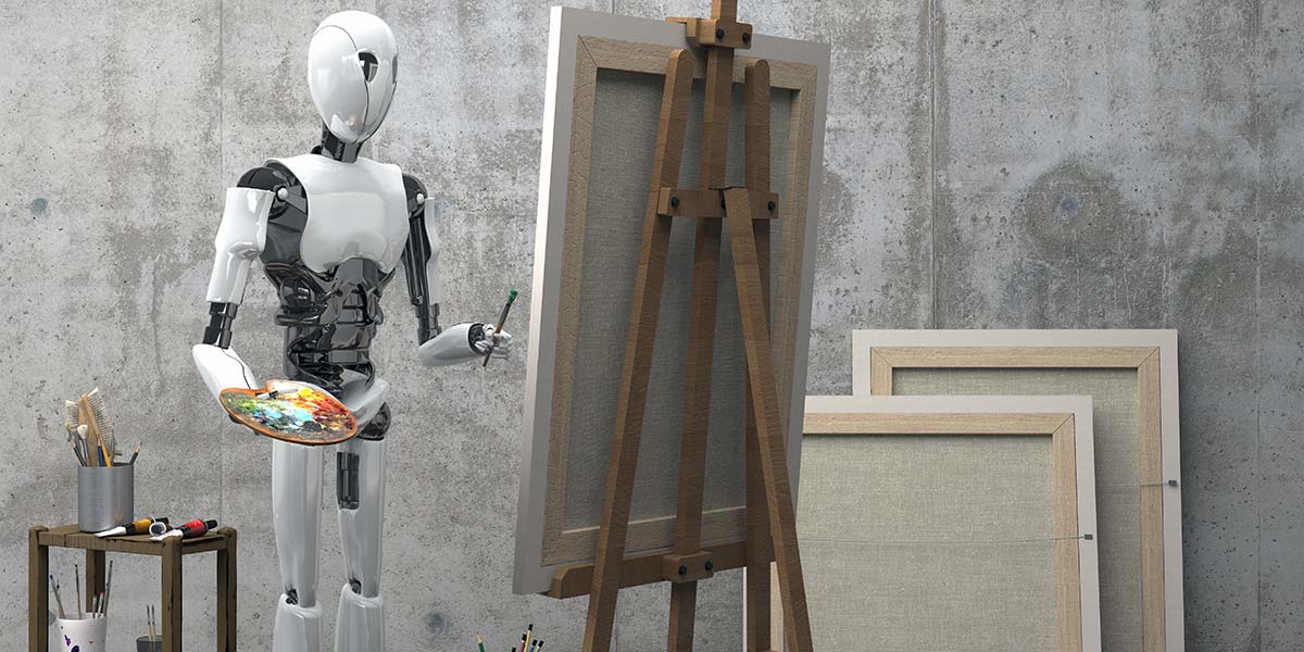
Meet Bot Ross
By Sam DiPietro, Brett Sawka, Rohan Shah View In Digital Edition
Between the three of us, as engineering students, drawing just isn’t something we’re any good at. Fortunately, we are good at engineering. So, by extension, being good at engineering means we’re actually great at drawing. That is, after we build a robot to draw things for us! Enter Bot Ross: the ever-precise robot built to draw any picture your heart desires (as long as you can find a version of that picture with a quick Google image search, of course).
Bot Ross is an easy-to-use machine capable of turning an image from your computer into an accurate sketch. Driven by a PIC32MX microcontroller, two H-bridge circuits for controlling stepper motors, and a serial communication interface with a Python script run on any computer, you can see Bot Ross come to life.
It draws with a pen attached to a servomotor controlled rack and pinion mechanism to move the pen up and down, which moves in two dimensions using stepper motors which turn threaded rods.
With a careful control algorithm, a linear interpolation of the desired image can be drawn in roughly 10 minutes. It works with any image you upload to the system, meaning infinite masterpieces await.
Electronics
To give Bot Ross the ability to think, we needed to add a brain. While there are many different options for control, we decided to go with a PIC series microcontroller which would give us all the computing power we’d need to draw and store images.
The PIC is a fine microcontroller, but we needed to first install it onto a printed circuit board (PCB) where it could receive power, distribute signals, and connect to a laptop.
On the PCB, we added a port expander, which gave the PIC an extra 12 input/output pins; a color LCD display so that we could debug our programs; and finally, a low current power supply to give power to just the components on the PCB. This board ran the C code we wrote to operate the stepper motors and drawing algorithm.
Responsible for Bot Ross’s entire range of motion, the motors needed to be precise and accurate — much like the arms of his namesake. We decided to go with stepper motors as they offered not only accuracy but also range of motion.
Stepper motors are a special kind of motor, containing tiny “steps” that you can power. This means that the motor is essentially quantized into small, precise values which are easy to program. When you apply a voltage to each of the “steps” — controlled by two coils of wire called inductors — the gear on the inside aligns, turning the motor by a small degree. By applying specific patterns to the motor, Bot Ross would be able to precisely move to any location on the paper.
Much like a human bicep that is bigger than the forearm, we used two different sized motors so that one motor could support the weight of the other. Just like the bicep, the big motor would not only have to move up and down the page, it would also have to carry around Bot Ross’s “hand” which held the other stepper motor and the pen.
Stepper motors (while very accurate) take a lot of power to operate — too much for our microcontroller to directly supply. The good news is, our microcontroller doesn’t have to actually do the heavy lifting. It just has to act as the operator.
Using H-bridges, we can control the flow of current through each of the motor coils that act as electromagnets. By alternating the direction of current flow in each coil, the electromagnet can be activated in such a manner that the shaft rotates in discrete amounts.
The current direction in each coil also dictates whether the motor turns clockwise or counter-clockwise. This is shown in Figure 1.
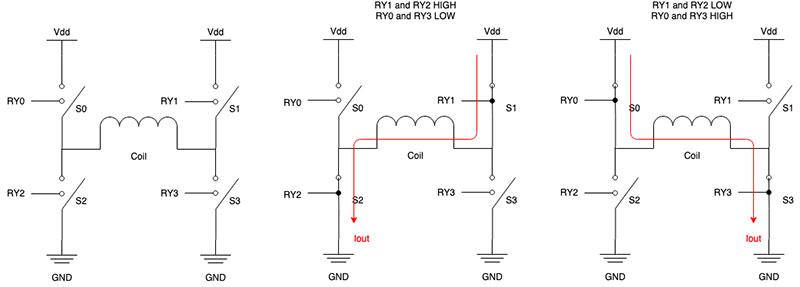
FIGURE 1. H-bridge current flow.
A full schematic of the system is shown in Figures 2 and 3.
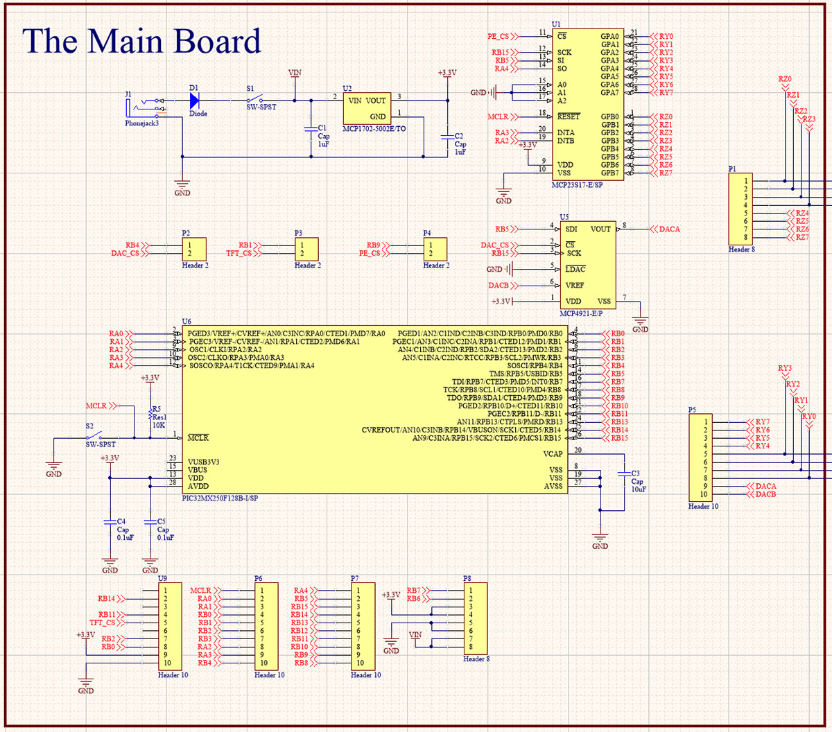
FIGURE 2. Schematic of main board.
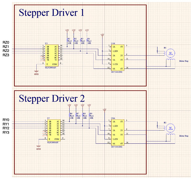
FIGURE 3. Schematic of stepper drivers.
Coding It Up
The software side of Bot Ross comes in three parts, each of which work together to drive the entire system. We have our motor control code, which is needed to work with our circuitry to get the steppers moving and our servo to lift the pen up and put it down. With that established, we needed a script to process images, formatting image data in a way that works well with our motor controlling code. This script also includes our method of communicating that image data from a computer to our PIC32MX microcontroller.
Finally, the most visible part of our code comes with the control algorithm, which interfaces the data sent over by our image processing script with our motor control code. When it all comes together, we have everything we need to get Bot Ross to draw some pictures.
When starting to code, we figured the best place to begin was with getting our motors moving, since a robot that can’t move wouldn’t do a whole lot. With our motor controller circuitry already built, we dug into determining the right inputs to that circuitry to accomplish three main things: spin a motor at the right time; turn it the exact right number of degrees; and get it to spin in the direction we wanted.
To make stepper motors move, they require two carefully timed pulse pairs coming from our microcontroller to the H-bridge inputs. A “pair” of pulses in this case involves two pulses which are exactly opposite each other; meaning when one pulse is on, the other is off, and vice versa.
We needed to generate two of these pairs, one of which was offset from the other by exactly half the length of a pulse. This is best described using a diagram like the one in Figure 4.
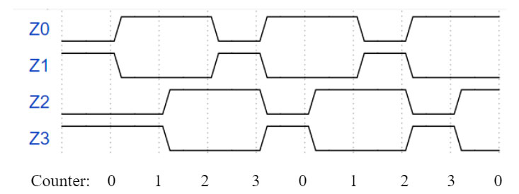
FIGURE 4. Stepper motor control signal waveforms.
Since timing is key, the best way to generate these pulses was to use one of the PIC32MX’s periodic interrupt timers. We can load the hardware timer with some value (corresponding to an amount of time), and it counts down to zero while other code runs on the CPU. Once the timer reaches zero, it interrupts whatever code is currently running in order to do something else.
In our case, that “something else” was to turn on or off the GPIO pin used to send out pulses. This chunk of code — called an interrupt service routine (ISR) — would flip pins on or off to create the pulse form above. If we were to let the ISR do this every single time it was triggered, that would mean the attached motor would always be moving in the same direction. We needed a way to change direction, and only move when we wanted to.
We accomplished both these things by setting up some global control variables for controlling our two motors. This gave the ISR a way to check whether the user (or the picture-drawing program) actually wanted the motor to move. Figuring out the direction worked similarly.
We could tell the ISR whether the motor should spin clockwise or counter-clockwise, and it checks every time. If the direction variable is a 1, the motor spins clockwise with the ISR-generated pulses shown above. If it’s a 0, the ISR uses the below waveforms to make the motor spin counter-clockwise.
With all this established, it was time to figure out the system for actually drawing pictures. Since each drawing is basically just a map of X-Y coordinates, we needed to figure out exactly what one coordinate meant. We ended up deciding that each coordinate — corresponding to one pixel on an image — would be 1 mm by 1 mm.
Our motor control code could easily support drawing millimeter-long lines, which gives picture drawing great precision. With our motors controlled and a convention for how an image should appear, we now needed a way to get pictures involved. This required a script for image processing, or having a computer look at a picture and turn it into arrays of numbers.
The goal here was to break an image down to a map of X-Y coordinates, then figure out the best way for Bot Ross to connect the dots in that map. Since images would be coming from a computer rather than the microcontroller, we decided to write this part of the code using Python to take advantage of easier-to-use arrays and the OpenCV library for computer vision and image processing.
Using OpenCV, we can use an algorithm called the Canny algorithm to do an edge detection of an image. An “edge” is any kind of boundary that you can see between shapes in an image. This algorithm takes an image and creates that X-Y map of edges.
With that 2D map of the image’s edges, we wrote an algorithm suitable for Bot Ross to draw the image as efficiently as possible. The algorithm starts at the top right of the X-Y map and finds the first coordinate where an edge actually is. The stepper motors turn on, move the pen to the right point, and place it down on the paper.
Next, Bot Ross looks for any adjacent points which need to be drawn. If there is one, the pen moves there, drawing the first little bit of the picture. Then, the algorithm looks for points adjacent to that point.
This process continues until it finds an “end” point with nothing adjacent to it. When that happens, the pen goes up and it retraces its steps, finding any points that had another adjacent point which weren’t drawn the first time. The pen goes down, and the process happens again, just with a new starting point. This same process happens over and over, until the pen is back at that very first point without any adjacent points to draw.
By now, there should be some lines and curves, all connected to each other. To keep drawing, Bot Ross starts over. It finds a new undrawn point, places the pen, and looks for adjacent pixels. With this algorithm running over and over (and over) again, eventually every single pixel will be found and the entire image will be sketched.
This process is based on a common algorithm called depth-first search2, which is often used for robots to traverse their surroundings. In this case, we used it to give instructions for a robot to draw a picture.
With software and hardware in place, it was time to perfect the mechanics behind picture drawing.
The Build
We spent a lot of time writing code and designing circuitry to make the plotter run well, but to put it all together in one system, we needed to physically construct Bot Ross. The system had three degrees of freedom; two of which were the stepper motors moving along the X and Y axes, with the third degree being the pen moving up and down. Take a look at Figure 5.
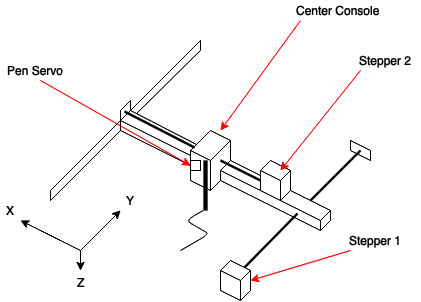
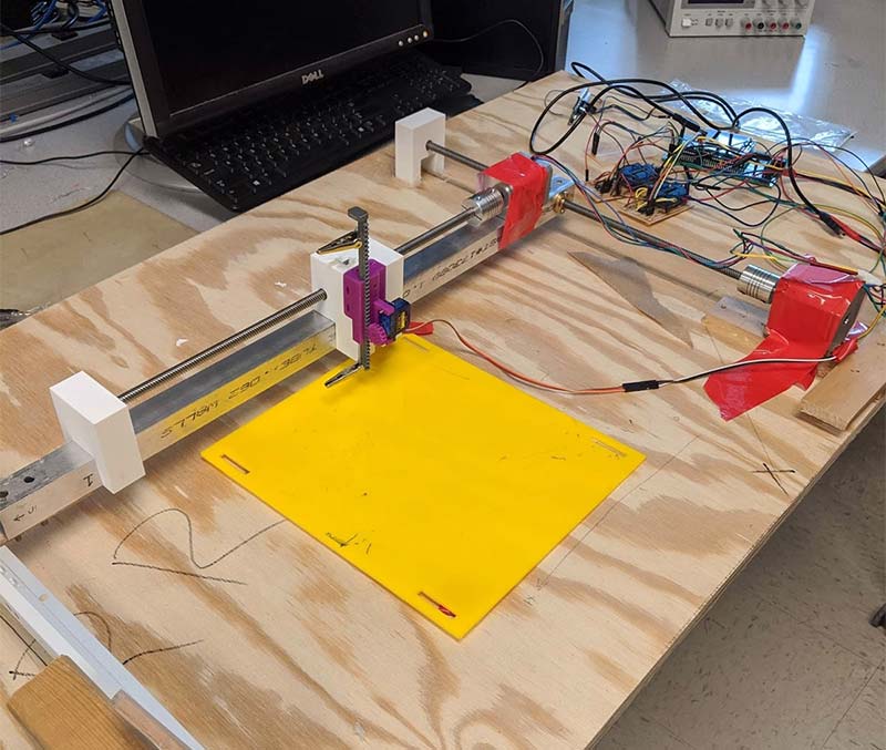
FIGURE 5. Physical design block outline (top) and construction (bottom).
An important part of using the stepper motors was having a method of turning their rotational motion into linear motion. This was done using two lead screws which are similar to threaded rods, and allowing the turning motion of the stepper motors to become linear motion.
Since the stepper motors only have a metal shaft to use for any kind of fixture, collars were needed to connect the lead screw to the motor. Also, each lead screw has a nut which connects to the object that is moving across the axis.
For the big stepper motor, the nut was attached to the smaller arm that held the second smaller motor. For the smaller stepper motor, the nut was attached to the block that held the actuation mechanism for the pen.
While one end of the lead screws was fixed to the shaft of the stepper motors with collars, the other ends were held in place at a level height by custom 3D-printed screw holders. These holders were essentially blocks, with openings to allow the screws to be propped up instead.
To allow the smaller arm to move smoothly when the big motor was stepping, we used a drawer slide (Lowe’s item #380974) to reduce the frictional resistance on the arm when moving. These slides are mechanisms found in drawers pretty much anywhere. They’re basically rails with supporting wheels that allow the support to move across it with little friction.
This reduction of friction was important due to the nature of our design. Any friction on the free end of the smaller motor arm would cause “missed” drawing as the arm would bend without the pen moving the specified distance. We sprayed WD-40 on the drawer slide as well to ensure the support was not sticking to any part of the slide rail when moving the entire distance across.
To make the pen move up and down, a 3D-printed rack and pinion mechanism obtained from the Thingiverse website was used in conjunction with a micro servo to allow the pen to move linearly up and down. This mechanism was a highly important component to our project because it allowed us to fine-tune the position of the pen when drawing. We wanted our artistic creation to be great!
A rack and pinion works similar to the way the lead screws work in our project. The pinion is a gear that attaches to a servo, and when it rotates, it moves the rack holding the pen. Refer to Figure 6.
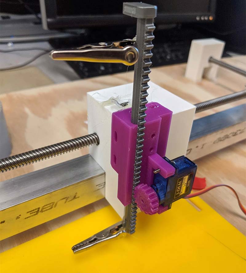
FIGURE 6. The rack and pinion mechanism.
The final part of the construction was attaching everything to the wooden base. This project was done with a relatively small budget, so we resorted to the cheap (yet very effective) method of hot gluing to attach all the components onto the base.
As we later noticed, this wooden base was quite warped from its previous use, so we had to place another platform on the base with small supports underneath to create a level drawing surface.
Happy Accidents
As with all engineering projects, problems and bugs arise mid-build and need to be addressed. Nothing is ever perfect on the first try, and Bot Ross was no different. For the first few runs of Bot Ross, the robot would slowly start drawing the image over itself, getting lost on the large page.
Thankfully, we included an onboard display which allowed Bot Ross to tell us that it thought it was in the right position. Figure 7 shows an image of the distortion that we kept on noticing.
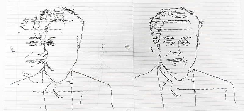
FIGURE 7. Distorted image (left) and corrected image (right).
No matter what we tried, we couldn’t figure out why the image would keep on shifting to the left. It wasn’t until the late hours of the night that we finally figured out what was plighting Bot Ross. Just like having a proper canvas to paint on, we realized that Bot Ross didn’t have a level surface to draw on.
When the pen was down and moving to the right (uphill), it would go slower than if it was drawing downhill. However, this proved to be no problem as it was constant and calibrated out.
By simply adding a correction factor — an additional step for every 10 going uphill — we were able to counteract the force of going uphill and re-center the drawing.
As stated, in all projects bugs are going to appear, and it was extremely useful for us to have accounted for the potential for bugs from the get-go with the inclusion of the debugging terminal.
The Masterpiece
After weeks of long hours spent in the lab, we did it. We had finally drawn a complete image. We finally drew a picture of the tech mogul, Elon Musk (Figure 8).

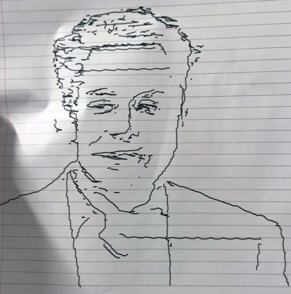
FIGURE 8. Original image of Elon Musk (top) and drawn image of Musk (bottom). The left image by Duncan.Hull is licensed under CC BY-SA 4.0. The image by Duncan.Hull is shown cropped in Figure 8 as that was the optimal aspect ratio determined to be used for the plotting system. The image was not modified in any form other than cropping.
Due to the constraints of the plotter, the edge detection algorithm was run on only the upper portion of the digital image, as shown by the drawing.
Although the contoured version of the image doesn’t look exactly like the original, almost all of the portrait outline and facial details are captured. The suit is the most clear part; you can even see the outline of his collar.
Since the stepper motors were not that fast, it took about 15 minutes to draw the picture of Musk, but the time was different for every image. The aspect ratio of the drawn image is slightly different from the original, but that could be easily fixed by adjusting the number of steps between coordinates in the X and Y axes.
We learned a lot from the challenges this project presented and succeeded in creating a “masterpiece.” Designing Bot Ross was a rewarding experience in collaborating with a team towards a common goal and learning how to efficiently use resources to make a great project.
Parts List
| ITEM | QTY |
|---|---|
| Threaded Rods | 2 |
| Stepper Motors | 2 |
| Shaft Couplers | 2 |
| Drawer Slide | 1 |
| Big Board | 1 |
| Port Expander | 1 |
| MicroStick2 | 1 |
| PIC32MX | 1 |
| Jumper Cables | 19 |
| Header Pins | 8 |
| Dual H-Bridge Motor Drivers (four pack) | 1 |
| PLA for 3D Prints |
Resources
Link to Project Web Page: http://people.ece.cornell.edu/land/courses/ece4760/FinalProjects/f2019/bas335_rns85_sdd58/bas335_rns85_sdd58/bas335_rns85_sdd58/index.html
Link to Project Video: https://www.youtube.com/watch?v=UoiOHu-NbZk&t=3s
OpenCV Python Library: https://opencv.org
Explanation of Depth-First Search: https://en.wikipedia.org/wiki/Depth-first_search
Rack and Pinion 3D object files: https://www.thingiverse.com/thing:3170748
Richelieu 20” drawer slides (purchased at Lowe’s): https://www.lowes.com/pd/Richelieu-2-Pack-20-in-Drawer-Slide/50041730
Microchip Documentation on Stepper Motors: https://www.microchip.com/en-us/solutions/motor-control-and-drive/motor-types/stepper-motors
Article Comments