
Talking With Light
By Gordon McComb View In Digital Edition
Whenever you program your robot, you're telling it what to do. So, how about when your robot needs to talk back? You might use sound to allow your robot to communicate with you. Or, you can use a more direct — and often easier — way: with good old fashioned light.
Using light to provide feedback for your robot can be as simple as a single LED, or more complex using multiple LED colors. A benefit of talking with light is that it also attracts attention. It can bridge the psychological gap between machine and person. Your robot can draw in humans by using a variety of bright lights and dazzling colors.
In this article, we’ll discuss simple techniques to communicate using light with your Arduino-based robot. The projects are simple to do, with only basic components and wiring needed. Most cost a couple bucks.
Communicating With LEDs
One light-emitting diode (LED) is all it takes for your robot to communicate with you. The language may not be elegant and the conversations are amazingly short, but it gets the job done. When you don’t need a talkative bot you can use a single LED, or for more words, you can use multiple LEDs or seven-segment LED display panels.
The basic LED feedback circuit is shown in Figure 1.
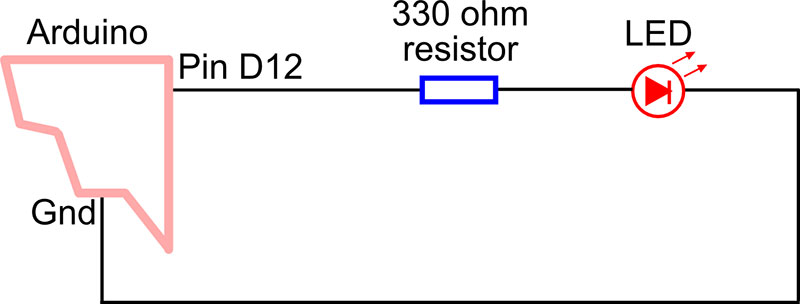
FIGURE 1. Basic connection for illuminating an LED via a microcontroller pin. Bringing the pin HIGH turns the LED on.
It uses just one of the I/O pins of your robot’s Arduino, along with a current-limiting resistor and an LED. Code running in your Arduino is demonstrated in Listing 1.
void setup() {
pinMode(12, OUTPUT); // Make D12 an output
}
void loop() {
digitalWrite(12, HIGH); // Turn LED on
delay(500); // Wait 1/2 second (500 ms)
digitalWrite(12, LOW); // Turn LED off
delay(500);
}
Listing 1.
It merely turns the LED off. Vary the delay value to make the LED flash on and off at a faster or slower rate. This sketch is just a variation of the Blink example that comes with the Arduino software.
Remember that you’re not limited to merely lighting an LED to show status. You can flash the LED using different patterns to communicate more variations. Use Morse Code to relay a variety of conditions or to “speak” phrases.
If you don’t know Morse Code, you can invent your own system. Table 1 shows just a few ideas. Note that in each case, there’s an Off pause between the three-flash sequence.
| Sequence | Meaning |
| Short-Short-Short | Status A-OK |
| Long-Long-Long | Unknown Trouble |
| Long-Short-Long | Battery Low |
| Short-Long-Short | Cannot Read Sensors |
| Short-Long-Long | Goal Reached |
| ... and so forth |
Table 1.
Put the LED where it’s easy to see, and select a component large and bright enough to make it visible from across the room — the LED connected to pin 13 on the Arduino just doesn’t cut it in most instances. I like to use large 5 mm bright red or yellow LEDs mounted on the top of the robot that can be seen at any angle.
Use multiple LEDs when you want to quickly convey operating or sensor status. For example, you might light an LED each time one of the bump switches or proximity detectors sense an object. You can then see how the robot responds to the condition, such as running your “back up and turn the other way” code. You know there’s a problem if an LED doesn’t light when it should, or lights up but the robot doesn’t take the proper action.
When only a small number of LEDs are needed, you can wire them directly to the I/O pins of your microcontroller. You simply duplicate the circuit and code from above, and use a different output pin assignment for each LED.
If you want to use more than four or five LEDs, then you probably don’t want to dedicate an I/O pin for each one. With a simple serial in parallel out (SIPO) shift register, you can turn three pins into eight. Refer to Figure 2 for a schematic using a 74595 SIPO integrated circuit.
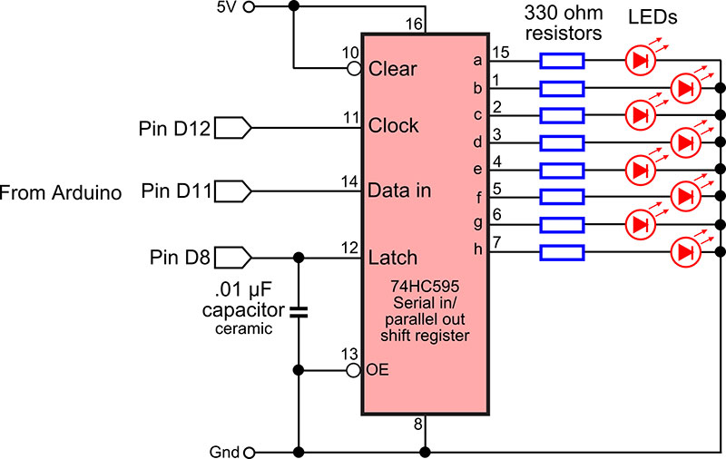
FIGURE 2. A 74595 serial-in, parallel-out (SIPO) shift register converts just a few microcontroller I/O lines to eight outputs. Any combination of outputs can be turned on at one time.
This chip is widely available and inexpensive at under $1; you can select any member of the ‘595 family such as the 74HC595 or 74HCT595 — whatever is available to you.
Sample program code for the Arduino is shown in Listing 2.
int latchPin = 8; // Connected to Latch pin
int clockPin = 12; // Connected to Clock pin
int dataPin = 11; // Connected to Data pin
void setup() {
// Set all pins to output
pinMode(latchPin, OUTPUT);
pinMode(clockPin, OUTPUT);
pinMode(dataPin, OUTPUT);
}
void loop() {
// Count 0 to 255
for (int val = 0; val <= 255; val++) {
// Disable update during count
digitalWrite(latchPin, LOW);
// Shift out bits
shiftOut(dataPin, clockPin, MSBFIRST, val);
// Activate LEDs
digitalWrite(latchPin, HIGH);
// Short delay to next update
delay(100);
}
}
Listing 2.
The shift register works by first setting the latch line to LOW, and keeping it there for the time being. Then, eight bits of data is sent bit by bit to the data pin of the chip. For each bit, the clock pin on the ‘595 is toggled to tell the chip that new data has been sent.
The Arduino makes sending serial data easy because it packages up the data and clock activities in one simple statement: shiftOut. To use this statement, you specify the number of the data and clock pin, the order of the data to be sent, and the value — from 0 to 255 — you wish to use.
shiftOut(dataPin, clockPin, MSBFIRST, numberValue);
After all the shifted out data has been sent, the program returns the latch pin to HIGH. This sets the output pins of the 74595 chip, illuminating the LEDs as desired.
Robo Talk with Multi-color LEDs
Some LEDs are engineered to produce more than one color.
- Bi-color LEDs contain red and green LED elements. You control which color is shown by reversing the voltage to the LED. You can also produce a yellowish-orange by quickly alternating the voltage polarity.
- Tri-color LEDs are functionally identical to bi-color LEDs, except that they have separate connections for the red and green diode.
- Multi-color LEDs contain red, green, and blue LED elements. You control which color to show by individually applying current to separate terminals on the LED.
Figure 3 shows how to connect a bi-color LED to two Arduino pins.
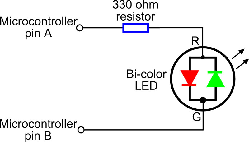
FIGURE 3. Connecting a bi-color LED to two I/O pins of a microcontroller. To display one of the colors, make its pin HIGH. Quickly alternating between the two pins produces a combination hue of the two colors combined.
To turn the LED off, put both pins LOW. To turn on one color or the other, put one of the pins HIGH. Refer to Table 2.
| Pin A | Pin B | LED Output* |
| LOW | LOW | Off |
| LOW | HIGH | Green |
| HIGH | LOW | Red |
| Pulse** | Pulse** | Orange |
* The actual color depends on how you connect the LED. Some bi-color LEDs display other than red and green.
** When pulsing, one pin is LOW while the other is HIGH. Pulse at a rate of at least 10 times per second. That way, your eyes will blend the flashes into a single combination color.
Table 2.
As an example, the following code for the Arduino toggles between the two colors of a bi-color LED:
digitalWrite(led1, HIGH);
digitalWrite(led2, LOW);
delay(1000);
digitalWrite(led1, LOW);
digitalWrite(led2, HIGH);
delay(1000);
For the mixed color effect, simply toggle between the two colors more quickly. Try reducing the delay from 1,000 milliseconds (one second) to 10 milliseconds (1/100th of a second).
Only one diode in a bi-color LED can be on at any time. Recall that in a tri-color LED, each diode has its own connection lead so you can switch either one on or off. You can also have both on at the same time, mixing the colors together.
Figure 4 shows how to connect a tri-color (three lead) LED to the Arduino (or other microcontroller). Note that each diode in the LED gets its own current-limiting resistor.
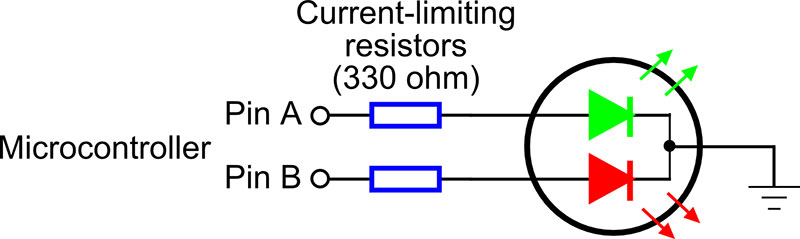
FIGURE 4. Connecting a tri-color LED to two I/O pins of a microcontroller. Either or both of the diodes can be turned on at once.
See Listing 3 for a short demonstration program of toggling a tri-color LED from red to green to orange. Refer to Table 3.
int redPin = 9; // Red diode of LED
int greenPin = 10; // Green diode of LED
void setup() {
pinMode(redPin, OUTPUT);
pinMode(greenPin, OUTPUT);
}
void loop() {
digitalWrite(redPin, HIGH);
delay(500);
digitalWrite(redPin, LOW);
delay(500);
digitalWrite(greenPin, HIGH);
delay(500);
digitalWrite(greenPin, LOW);
delay(500);
digitalWrite(redPin, HIGH);
digitalWrite(greenPin, HIGH);
delay(500);
digitalWrite(redPin, LOW);
digitalWrite(greenPin, LOW);
delay(500);
}
Listing 3.
| Pin A | Pin B | LED Output* |
| LOW | LOW | Off |
| LOW | HIGH | Green |
| HIGH | LOW | Red |
| HIGH | HIGH | Orange |
* Actual colors depend on the LED you’re using.
Table 3.
Finally, multi- or RGB-color LEDs have a red, green, and blue diode. These three primary colors can be displayed independently, or in different combinations to produce many other colors. You use these the same as with a tri-color LED, except that you need a third I/O pin to control the additional color.
Figure 5 shows the connection scheme for a multi-color LED, plus a testing rig so you can experiment with how they work.
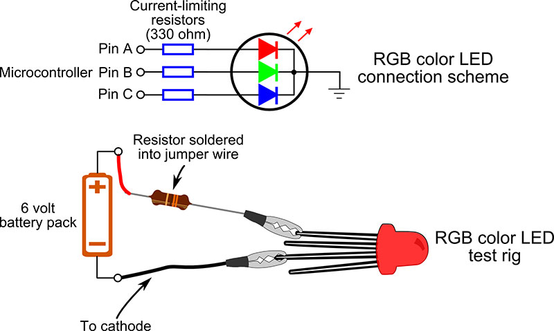
FIGURE 5. Connecting a multi-color (red-green-blue) LED to three I/O pins. Any color in the rainbow can be reproduced by altering the brightness of the three diodes.
Solder a current-limiting resistor (for example, 330 to 470 W) inline with the jumper wire. Connect the – terminal of the battery to the cathode lead of the LED, and then touch each of the three anode leads in turn to watch the colors.
Recall that you can mix colors by turning on more than one diode in the LED at a time. Thanks to the Arduino’s PWM (pulse width modulation) feature, you can vary the intensity of the light, and create thousands of color combinations.
The Arduino sketch in Listing 4 shows how to use the analogWrite statement which produces a PWM signal on specific pins of the microcontroller.
int redPin = 9; // Red diode of LED
int greenPin = 10; // Green diode of LED
int bluePin = 11; // Blue diode of LED
void setup() {
// Start with everything off
analogWrite(redPin, 0);
analogWrite(greenPin, 0);
analogWrite(bluePin, 0);
}
void loop() {
// Fade red in and out
for(int fadeValue = 0 ; fadeValue <= 255; fadeValue++) {
analogWrite(redPin, fadeValue);
delay(5);
}
for(int fadeValue = 255 ; fadeValue >= 0; fadeValue--) {
analogWrite(redPin, fadeValue);
delay(5);
}
// Fade in blue, then add green, and finally red
for(int fadeValue = 0 ; fadeValue <= 255; fadeValue++) {
analogWrite(bluePin, fadeValue);
delay(5);
}
for(int fadeValue = 0 ; fadeValue <= 255; fadeValue++) {
analogWrite(greenPin, fadeValue);
delay(5);
}
for(int fadeValue = 0 ; fadeValue <= 255; fadeValue++) {
analogWrite(redPin, fadeValue);
delay(5);
}
// Wait 2 seconds before doing it all again
// Note that all three colors may not create a
// pure "white" because the diodes in the LED
// do not overlap one another
delay(2000);
analogWrite(redPin, 0);
analogWrite(greenPin, 0);
analogWrite(bluePin, 0);
delay(500);
}
Listing 4.
We’ll be using digital pins D9, D10, and D11 for connecting to a multi-color LED (don’t forget the current-limiting resistors!).
Note: The hookup diagrams for the tri- and multi-color LEDs show common cathode devices — that is, the cathode (negative) end of all the diodes in the device are tied together. Multiple color LEDs are also available in common anode style, where the anode (positive) ends are linked together. The concept of using these are the same though, of course, you must reverse the wiring. The LED is turned on when the cathode connection is brought LOW.
Linguistics with Seven-Segment LED Displays
Your robot can also talk to you using one or more seven-segment numerical LED displays. You can light up the segments to produce numerals, in which case your robot can output up to 10 “codes” to indicate its status. For instance, 0 might be OK, 1 battery low, and so on.
You can illuminate the segments to make non-numeric shapes; turn on each segment individually or in combination. Figure 6 shows some variations, including an E for Error, H for Help, and numerous symbols that can mean things like which motor is supposed to be on, or a battery level indicator.
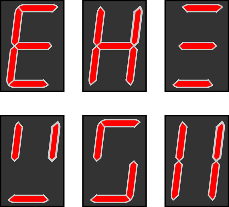
FIGURE 6. Unusual non-numeric shapes can be created by activating selected segments of a seven-segment LED display. Use this system to display numbers (of course) or codes.
The easiest way to show numerals on a seven-segment display is to use a display driver IC, such as the CD4511 or 7447. These chips have four inputs and eight outputs — seven outputs for the numeric segments, and an eighth for the decimal point which we won’t be using in this example.
To display a number, set its binary coded decimal (BCD) value at the A-D input lines. For example, to display a 3, use the binary value 0011. Refer to Table 4.
| 4511 Inputs | ||||||
| BCD | A | B | C | D | 4511 Outputs | Numeral |
| 0000 | 0 | 0 | 0 | 0 | 1111110 | 0 |
| 0001 | 1 | 0 | 0 | 0 | 0110000 | 1 |
| 0010 | 0 | 1 | 0 | 0 | 1101101 | 2 |
| 0011 | 1 | 1 | 0 | 1 | 1111001 | 3 |
| 0100 | 0 | 0 | 1 | 0 | 0110011 | 4 |
| 0101 | 1 | 0 | 1 | 0 | 1011011 | 5 |
| 0110 | 0 | 1 | 1 | 0 | 0011111 | 6 |
| 0111 | 1 | 1 | 1 | 0 | 1110000 | 7 |
| 1000 | 0 | 0 | 0 | 1 | 1111111 | 8 |
| 1001 | 1 | 0 | 0 | 1 | 1110011 | 9 |
Table 4.
Refer to Figure 7 for a hookup diagram for the CD4511 to a common cathode seven-segment LED display.
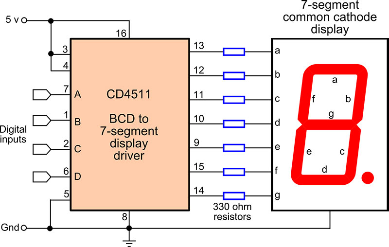
FIGURE 7. Connection diagram for a CD4511 (binary coded decimal) to seven-segment driver. Numbers appear in the display based on the binary coded values on the A to D input pins.
Listing 5 is a simplistic Arduino program that sends different values to the CD4511, lighting up different segments. (You can use the same general concept with individual LEDs.)
int outA = 8; // Connected to A pin on 4511
int outB = 9; // Connected to B pin
int outC = 10; // Connected to C pin
int outD = 11; // Connected to D pin
void setup() {
// Set all pins to output
pinMode(outA, OUTPUT);
pinMode(outB, OUTPUT);
pinMode(outC, OUTPUT);
pinMode(outD, OUTPUT);
}
void loop() {
// Display 3
digitalWrite(outA, HIGH);
digitalWrite(outB, HIGH);
digitalWrite(outC, LOW);
digitalWrite(outD, LOW);
delay (1000);
// Display 9
digitalWrite(outA, HIGH);
digitalWrite(outB, LOW);
digitalWrite(outC, LOW);
digitalWrite(outD, HIGH);
delay (1000);
}
Listing 5.
The circuit in Figure 7 shows a common cathode seven-segment LED module; that is, all the LED segments in the display share the same cathode connection. Be sure yours is also a common cathode display, and not a common anode display.
Finally, here’s one more example to close out our discussion. Refer to Figure 8 on how you can connect a 74595 SIPO chip to a seven-segment display.
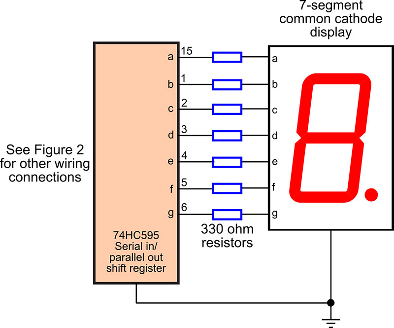
FIGURE 8. The 74595 SIPO shift register driving a seven-segment LED display. Using the shift register allows any combination of segments to light.
Use the Listing 6 sketch to send out eight bits to light the seven segments plus the decimal point.
int latchPin = 8;
int clockPin = 12;
int dataPin = 11;
void setup() {
pinMode(latchPin, OUTPUT);
pinMode(clockPin, OUTPUT);
pinMode(dataPin, OUTPUT);
}
void loop() {
// Write a regular 7
digitalWrite(latchPin, LOW);
shiftOut(dataPin, clockPin, LSBFIRST, B11100000);
digitalWrite(latchPin, HIGH);
delay(1000);
// Write some funky character
digitalWrite(latchPin, LOW);
shiftOut(dataPin, clockPin, LSBFIRST, B01110011);
digitalWrite(latchPin, HIGH);
delay(1000);
}
Listing 6.
With this setup, you’re still able to produce all 10 digits, of course, plus Predator-type alien language symbols that only you (and your robot) understand. SV
Article Comments