Make a Splash with an Underwater Quadcopter ROV — Part 1
By Theron Wierenga View In Digital Edition
Shortly after successfully building the ROV_Manatee — a remotely controlled underwater vehicle (see article here) — the thought of an underwater ROV built like a quadcopter came to mind. For a period of time, I explored this with the idea of using bilge pump motors to turn the four propellers. Later, with more exploration of various underwater designs, I decided to employ the same type of brushless motors used in quadcopters, and named the project Quad_ROV.
Introduction and Description
The new design adds a layer of complexity since electronic speed controllers (ESCs) must be used to drive the brushless motors. The question of using the brushless motors underwater didn’t seem to be much of a problem since (without the brushes) there is not much to short out underwater. These motors do have a bearing that could potentially develop a problem, but given the motors only cost a few dollars each, replacement is a simple solution for any issues that develop.
I gave the inside motor coils and connections an extra coating of urethane varnish made for electrical coils for some extra protection. A little oil on the bearing casing and the iron laminated stators inside the brushless motors reduces the problem of rust.
Model boat propellers were obtained that mated with the brushless motors. Traxxas makes propellers in both right and left hand propeller screws; numbers 1533 and 1534. Racerstar BR2205 brushless motors were used that come in both CW (clockwise) and CCW (counterclockwise) models.
The CW model comes with a normal (right hand) metric 5 mm thread for propeller attachment, while the CCW models have a left hand metric 5 mm thread.
Unfortunately, both Traxxas 1533 and 1534 have normal right hand CW threads for attaching to the shaft of a motor. Motors like this (sold in groups of four) will have two each of the CW and CCW threads. If you can’t purchase motors with right hand threads individually, you may have to purchase two groups of four to get four with right hand threads.
The first thing I assembled was a 450 mm quadcopter frame. Several companies make these kits, and basically provide you with a nice inexpensive platform to begin assembly. They can be found on Amazon, eBay, and several radio control websites.
The four motors are mounted onto the end of the arms of the frame, except they are mounted upside down from what is normal. Boat propellers push, while aircraft propellers pull. Many current versions of the quadcopter kit have a foot attached just underneath the motor mount; this will need to be cut off so the brushless motors can be mounted.
To reduce vibrations, the circular mounting plates are not used, and 1/4 inch thick Neoprene rubber is employed instead. The Adafruit 9-DOF (degrees of freedom) sensor board is quite sensitive to vibrations, as are most inertial measurement devices.
The arms across from each other have their motors turning in the opposite direction, and the motors of each arm turn in the same direction. With right and left hand propellers, all four propellers will be pushing the Quad_ROV upwards. This configuration is called Quad-X; refer to Figure 1.
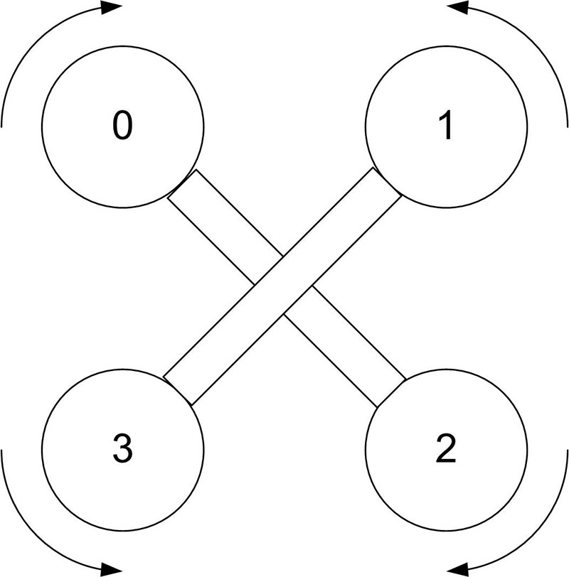
Figure 1. The Quad-X configuration.
How a Quadcopter Moves in Space
A quadcopter's four propellers are arranged so that two turn in one direction and two in the opposite direction.
From Newton's Third Law, we know that if all four propellers were turning clockwise, the quadcopter would spin counterclockwise. With two turning in each direction, the spin is cancelled out.
If all four motors turn at the same speed, the quadcopter will rise, hover, or lower, depending on the motor speed.
If motors 0 and 1 are decreased in speed while motors 2 and 3 are increased in speed, the quadcopter will pitch forward and move in the forward direction. Reversing this will cause the quadcopter to pitch backward and move backward.
If motors 1 and 2 are decreased in speed while motors 0 and 4 are increased in speed, the quadcopter will roll to the right and move in the right direction. Reversing this will cause the quadcopter to roll left and move left.
If motors 1 and 3 are decreased in speed while motors 0 and 2 are increased in speed, the quadcopter will yaw to the left and rotate to the left. Reversing this will cause the quadcopter to yaw right and rotate right.
This gives us four DOF of motion. As space consists of three dimensions, we could navigate the quadcopter, for example, without using yaw. However, it is convenient to be able to rotate the quadcopter, and yaw is usually included in the quadcopter's controls.
Attached to the bottom center plate of the frame kit is a 6 x 6 x 4 inch waterproof plastic junction box: a Cantex 5133710. These are normally used for wire connections outside a house or underground, and are fitted with a cover containing a rubber gasket.
This box houses the printed circuit board (PCB) which mounts the Teensy 3.1 microcontroller; four ESC units; the Adafruit 9-DOF sensor board; an Adafruit servo driver board; multiplexer circuit; five volt regulator; headers for connections between parts; a pressure sensor; and a miniature NTSC video camera, as well as other parts and all the needed connections.
This size box works quite well for fitting all the parts inside. I tried a 4 x 4 x 4 inch box, and while I could squeeze everything inside, working with it was just too difficult. With a custom designed PCB, a 4 x 4 x 4 inch box could probably be used.
When I designed the PCB, many additional general-purpose pads were added to accommodate additional circuitry. This worked very well when changes were necessary as the design progressed.
The pin-compatible Teensy 3.2 has replaced the Teensy 3.1, but since I had a Teensy 3.1 on hand, I used it. The additional program space and clock speed (compared to some of the Arduino models) were helpful with this project.
The Quad_ROV includes an onboard video camera with a standard NTSC video signal sent back up the tether on a twisted pair. This NTSC signal then connects to an RCA style jack mounted on the joystick controller box.
This is a very simple and inexpensive 12 volt camera, available in many styles on eBay or Amazon as well as other vendors.
The style I chose has a small sensor and lens mounted on a 1-1/2 inch square PCB that makes mounting it easy. This camera was selected because there’s not a steel case to magnetically interfere with the Adafruit 9-DOF. This camera is simply an aid when moving the Quad_ROV underwater since the image is not high quality.
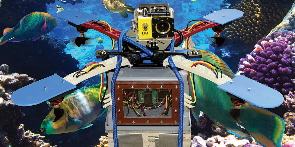
If higher quality video is desired, something like a watertight GoPro camera can be easily attached to the top platform of the Quad_ROV.
Construction
The 450 mm quadcopter frame kit was assembled according to the supplied instructions. I used stainless steel screws in place of the ones supplied, and used Loctite Blue Threadlocker on all the screws when assembling the frame.
As mentioned previously, the circular motor mounting plates weren’t used and 1/4 inch thick Neoprene rubber was substituted. Vibration can be a real problem for the sensors, and this greatly reduces vibration from the motors.
The motors are mounted upside down from a normal quadcopter (since the boat propellers push instead of pull as previously mentioned).
A 1/4 inch thick piece of expanded PVC measuring 6 x 2-3/8 inches was screwed to the bottom piece of the quadcopter frame. This piece then has two holes that allow 1/4 - 20 bolts to attach the plastic junction box. Stainless steel screws were used throughout (see Figures 2 and 3).
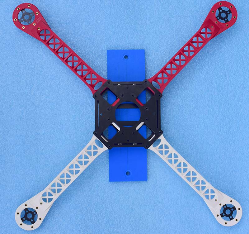
Figure 2. Top of the 450 mm quadcopter frame, before motor mount disks were replaced with Neoprene rubber.
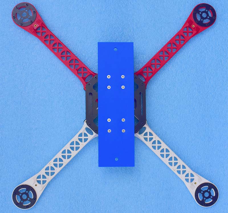
Figure 3. Bottom of the 450 mm quadcopter frame, showing 1/4 inch expanded PVC measuring 6 x 2-3/8 inches.
To reduce vibration between the arms and the junction box, three layers of 1/4 inch Neoprene rubber were used; one between the bolt head and washer and expanded PVC; one between the expanded PVC and junction box (as wide as the expanded PVC and the full length between the bolts); and one between the junction box and nut with washer.
Added to the top of the arms at the ends is a set of four 1/8 inch expanded PVC pieces attached above the motors. The ends were rounded, so these serve as propeller blade guards to prevent the propellers from hitting anything underwater.
The plastic junction box is pierced in several places and its watertight integrity is an absolute must. I began by drilling four sets of three holes in each box corner near the frame arms, at the bottom of the box. The box is mounted upside down with its cover facing down. Each hole had the base of a female bullet connector installed, with number 16 wire soldered into it that connects to the brushless motors. The female connector end sticks outside the corners of the box and the open end is flush with the inside of the box.
A liberal amount of marine epoxy holds the bullet connector in place and makes a watertight seal. Marine epoxy was also used to coat the solder joints on the wires from the bullets outside to the motor wires. The three mating male bullet connectors are soldered to the end of the three output wires of the ESCs. This makes disconnecting the ESC wires and removing the main PCB from the box easy. Switching two of the wires to reverse the direction of a brushless motor is also convenient with the bullet style connectors.
Half of a 1/2 inch threaded PVC coupling is also epoxied into a one inch hole on the backside of the box to mate with the end of the tether, which goes through a 1/2 inch PVC plug and is filled with marine epoxy. The tether was made from a 50 foot extension cord and 50 feet of Cat 5 cable. Screwing a 1/2 inch thick piece of Plexiglas against a rectangular hole in the front of the box makes a window for the NTSC camera. A rubber gasket between the two makes this watertight.
The last penetration of the box is for the pressure sensor, which uses 1/4 inch NPT threads. A 7/16 hole was drilled in the box and then threaded with a 1/4 inch NPT tap. Again, a rubber gasket on the inside with a washer makes the watertight seal.
The box cover comes with a lightweight gasket; this was replaced with one cut to shape from 1/8 inch thick rubber. When the cover is screwed tightly down, the plastic cover bends slightly at the corners which does not give a good seal.
This was remedied by placing a 6-3/4 inch square piece of 1/4 inch aluminum on top of the plastic cover with matching holes. The holes for the sheet metal type screws attaching the cover were drilled out and tapped for larger 10-24 machine screws.
The entire Quad_ROV is quite buoyant and needs additional weight for ballast. For testing, I duct taped together a group of 3-1/4 inch ceramic tiles. A square of four of these matches the box cover size nicely. Several layers of these squares duct taped together were temporarily attached to the box with two bungee cords. For a more permanent solution, a 6-3/4 inch square of thick aluminum would work well.
With four matching screw holes aligned with the top cover, this would serve double-duty by also flattening the plastic box cover for a good seal. I found that using just enough weight to make the Quad_ROV negatively buoyant was not enough and led to instability. The Quad_ROV needs a little extra weight to help with stability, and this weight needs to be centered at the bottom of the box (against the cover) to keep a low center of gravity.
I found five layers of the 3-1/4 inch ceramic tiles provided the right weight. Iron or steel should not be used for ballast, as this would affect the magnetic sensor in the Adafruit 9-DOF sensor. In addition, non-magnetic stainless steel screws and nuts (as well as nylon) were used throughout this project.
ESC Basics
Driving the ESC controllers with a Teensy 3.1 takes a special work-around. Normally, a sophisticated flight control board drives the ESCs on a quadcopter.
There are two things of absolute necessity to keep in mind when using ESCs. First, the ESCs must be calibrated, and second, the ESCs must only be powered on after servo signals set to the minimum value are sent to the ESCs. This minimum servo signal is detected immediately by the ESCs.
The throttle to the ESCs is controlled by a traditional servo signal. This signal typically varies from a 1,000 microsecond (one millisecond) pulse every 20 milliseconds to a 2,000 microsecond pulse every 20 milliseconds. This varying one to two millisecond pulse drives the output of the ESCs from minimum to maximum throttle.
As with most servos, the exact values for minimum and maximum output vary slightly and need to be tested. I found my ESCs did not shut down at exactly one millisecond. These values can also change depending on the setting of the calibration values.
If you power the Teensy 3.1 and the ESCs at the same time, it takes a second or two for the Teensy 3.1 to begin sending servo signals to the ESC. This results in the ESC being powered up in error mode and non-functioning.
On the previous design for the ROV_Manatee, I used a 12 volt automotive relay turned on with a Hall effect switch to power the system after the enclosure for the electronics was water sealed. Relays produce a magnetic field that will interfere with the operation of the flight sensors, so this is not an option for delaying power to the ESCs. Instead, a quad two-input multiplexer (74LS157) was used. One set of four inputs of the multiplexer are tied together and connected to a simple 555 timer circuit carefully tuned to produce the minimum servo signal.
When the Teensy 3.1, ESCs, multiplexer, and 555 timer are all powered up at the same time, the ESCs will immediately receive the minimum servo signal and power-up correctly. After the Teensy 3.1 has had a few seconds to power up, it switches the multiplexer inputs to receive the varying servo signals from the Adafruit servo driver board for normal control.
The 555 timer circuit shown in Figure 4 uses two additional diodes to produce a 50 Hz pulse with duty cycle less than 50%.
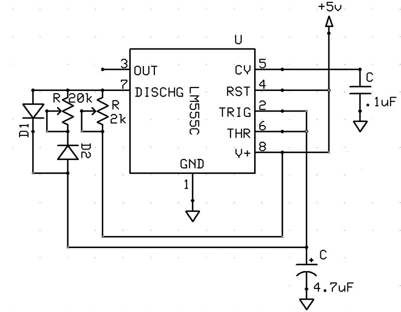
Figure 4. The 555 timer circuit used to produce the minimum servo signal.
The diodes assure that the charge current for the 4.7 µF capacitor only goes through the 2K variable resistor, while the discharge current goes through the 20K variable resistor. The 2K resistor is adjusted until the positive pulse is about one millisecond long, and the 20K resistor is adjusted until the pulse frequency is 50 Hz or 20 milliseconds.
An easy way to do this is to use an Arduino to measure the pulse width. A simple program like the following will read the one millisecond pulse. The output will be printed to the Arduino serial monitor in microseconds and should read about 1,000. The output from pin 3 on the 555 timer needs to be connected to pin 2 on the Arduino, along with a common ground wire between the two.
// Read pulses
unsigned long width;
void setup()
{
Serial.begin(115200);
pinMode(2, INPUT);
}
void loop()
{
width = pulseIn(2, HIGH);
Serial.print(“Width = “)
Serial.println(width);
delay(1000);
}
If the HIGH parameter in the pulseIn() function is changed to LOW, it will read the time between the high going pulses; this should be about 19,000 microseconds. Refer to Figure 5.
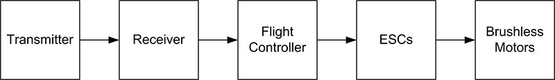
Figure 5. Block diagram of a traditional quadcopter.
The block diagram in Figure 6 shows an Adafruit servo driver board being used to send the servo signals to the ESCs via the 74LS157 multiplexer.
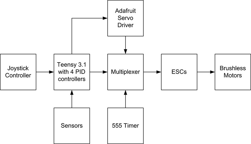
Figure 6. Block diagram of the Quad_ROV, with changes to power-up the ESCs.
Why not simply use the Servo library available for an Arduino or Teensy 3.1?
The answer is that using Serial3 on the Teensy 3.1 and the Servo library at the same time can sometimes cause problems. Instead, the Adafruit servo driver board is a simple workaround. It will send out the servo signals, and is controlled through the I2C interface that uses pins A4 and A5 on the Teensy 3.1. Adafruit provides a library for using this board, and a method to send out a servo signal looks like this:
pwm.setPWM(0, 0, motors[0]);
The first number in the parameter list is the channel number which is 0-15; although, only 0-3 is used for the four motors. The second number is the start of the pulse and is typically 0. The third number is the time the pulse ends, and can range from 0-4095, which is why they state the board has 12-bit resolution. Here’s an example. In setup(), we initialize the object and then declare the pulse frequency, which for a servo is 50 Hz:
pwm.begin();
pwm.setPWMFreq(50);
A 50 Hz pulse is 20 milliseconds long, and we divide this into 4096 parts. If we want a pulse length of one millisecond, this is 1/20 of 4096 = 204.8. Therefore, our third parameter, motors[0] should be equal to 205.
Actually, this method gives only an approximation of the output length. The actual measured output using 205 produces a 1.096 millisecond pulse. The simple program here will produce a table of servo pulse widths for given values of the third parameter in the pwm.setPWM() call. The output can be copied to a document and then used as a reference.
// Printing out Pulse Widths of Arduino Servo
// Driver
// Written for Teensy 3.1, 3.2 by Theron
// Wierenga
// January 2017
// Connect output 0 of Adafruit Servo Driver to
// pin 9 of Teensy 3.1/3.2
// Connect ground of Adafruit Servo Driver
// to ground of Teensy 3.1/3.2
// pin A5 of Teensy 3.1/3.2
// Connect SDA of Adafruit Servo Driver to
// pin A4 of Teensy 3.1/3.2
#define SERVOMIN 100
// this is the ‘minimum’ pulse length
// count (out of 4096)
#define SERVOMAX 400
// this is the ‘maximum’ pulse length
// count (out of 4096)
//
#include <Wire.h>
#include <Adafruit_PWMServoDriver.h>
// Called this way, it uses the default
// address 0x40
Adafruit_PWMServoDriver pwm = Adafruit_ PWMServoDriver();
int width;
void setup() {
delay(5000);
pwm.begin();
pwm.setPWMFreq(50);
// Analog servos run at ~50
// Hz updates
pinMode(9, INPUT);
Serial.begin(115200);
Serial.println(“Starting”);
Serial.println();
}
void loop() {
for (int param = SERVOMIN;
param <= SERVOMAX ; param++)
{
pwm.setPWM(0, 0, param);
delay(100);
width = pulseIn(9, HIGH);
Serial.print(“param = “);
Serial.print(param);
Serial.print(“ “);
Serial.print(“pulse width
= “);
Serial.println(width);
}
while (true) {} // Stop
}
There is another issue that needs to be addressed when using boat propellers on the brushless motors. These propellers are turning in water, so they produce a much greater resistance than those turning in air. Therefore, the brushless motors draw more current.
Figure 7 is a graph of the current draw of a brushless motor with a boat propeller attached.
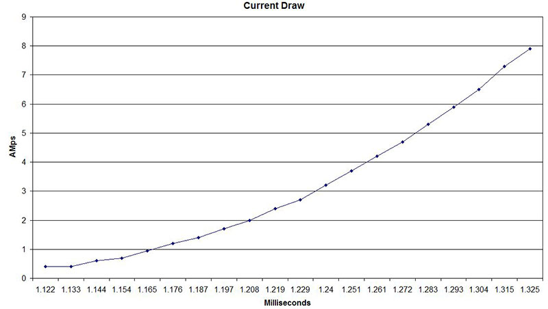
Figure 7. Current draw of a brushless motor with boat propeller attached.
Servo signals from 1,122 to 1,325 microseconds were sent to the brushless motor and the current draw recorded.
While air screw propellers can be driven up to the full servo signal of 2,000 microseconds, the graph shows that it starts to exceed the maximum current rating of 10 amps on the brushless motors at much less than 2,000 microseconds. Therefore, it is necessary to reduce the maximum servo signal so as not to exceed the current rating of the brushless motors.
Referring to Figure 8, note that the ESC has three wires the same color to connect to the brushless motor.
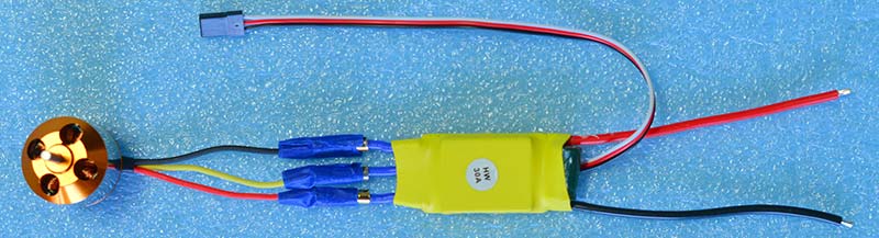
Figure 8. ESC temporarily connected to a brushless motor for calibration and testing.
They can be connected in any order, and switching two of the wires will turn the brushless motor in the opposite direction.
The opposite end of the ESC has a red and black wire to connect to the battery (I used a 12 volt sealed lead acid battery) and a three-wire servo connector. You MUST DISCONNECT THE RED WIRE on the servo connector to the ESCs. I did this on the PCB; i.e., that header pin is not connected to anything.
Many ESCs use the red wire to provide five volts to other circuitry on a quadcopter. If this wire is connected to other circuitry in our Quad_ROV and you apply 12 volts to the ESC, it may destroy that circuitry. The Teensy 3.1 only needs the data line and ground of this connector to operate the ESC.
Sensors
The Quad_ROV needs to be able to determine its position in space. For this task, I chose the Adafruit 9-DOF board. Using the software Adafruit supplies for this board, it’s a fairly simple matter to read off the pitch and roll angles directly in degrees, as well as the yaw or compass heading. These values are then compared to the desired values by the PID controllers and used to drive the brushless motors. As with many inertial measurement devices, the Adafruit 9-DOF is sensitive to vibration. Instead of directly mounting this sensor on the PCB, it’s suspended by small rubber bands from four stainless steel or nylon machine screws.
Double-sided foam tape was used to attach three small ceramic tile squares to the bottom of the Adafruit 9-DOF to give it added mass. This improves its inertia and resistance to vibration. Since the main PCB gets inverted when the box is mounted to the arms, the Adafruit 9-DOF is mounted upside down. The depth is measured by a pressure sensor — the output connected to pin A0
A word of caution on pressure sensors. eBay has a large number of these inexpensively priced, and after purchasing a couple, I found that they could not be used in water. Some vendors are now adding a warning about this, but not all.
After using these inexpensive models in water, I noted rust coming from inside the pressure opening and the readings were in error. These pressure sensors are meant for automotive use with oil or fuel — not water. I ended up using a Honeywell 50 PSI PX2AN1XX 050PAAAX.
This pressure sensor outputs an analog five volt signal. A resistor voltage divider can be used to bring this value down to 3.3 volts for input into the Teensy 3.1, thus extending its range. There are pads on the PCB for a fixed resister (4.7K) and 10-turn variable resistor (2K) voltage divider; the output is fed to pin A1. Whatever pressure sensor is used, be sure to test it at measured depths so that you can scale its output. The full schematic of the Quad_ROV is shown in Figure 9.
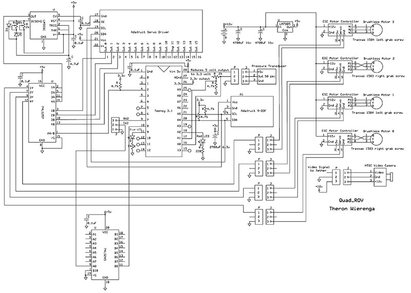
Figure 9. Quad_ROV schematic.
Figures 10 through 12 show different views of the Quad_ROV.
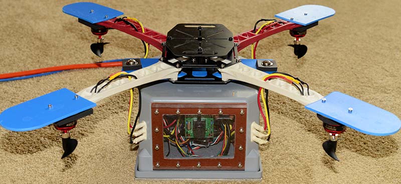
Figure 10. Front view of the Quad_ROV, looking into the video window.
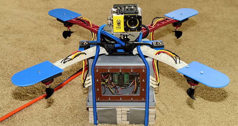
Figure 11. Quad_ROV with temporary ballast held in place with bungee cords. An inexpensive knockoff GoPro is attached to the top frame.
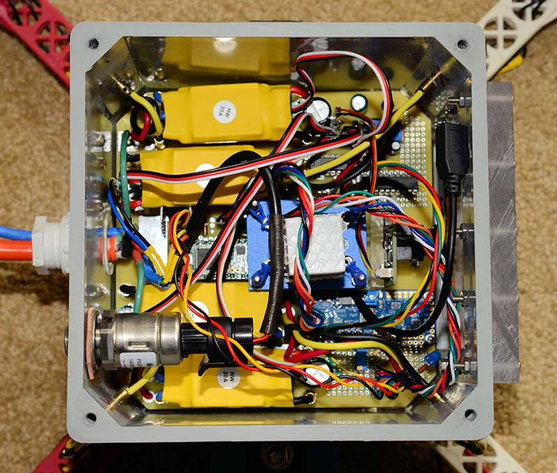
Figure 12. Looking down at the PCB in the box with all connections in place.
Figures 13 through 16 show each side of the controller development board.
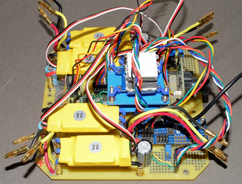
Figure 13. View of the PCB from the right side.
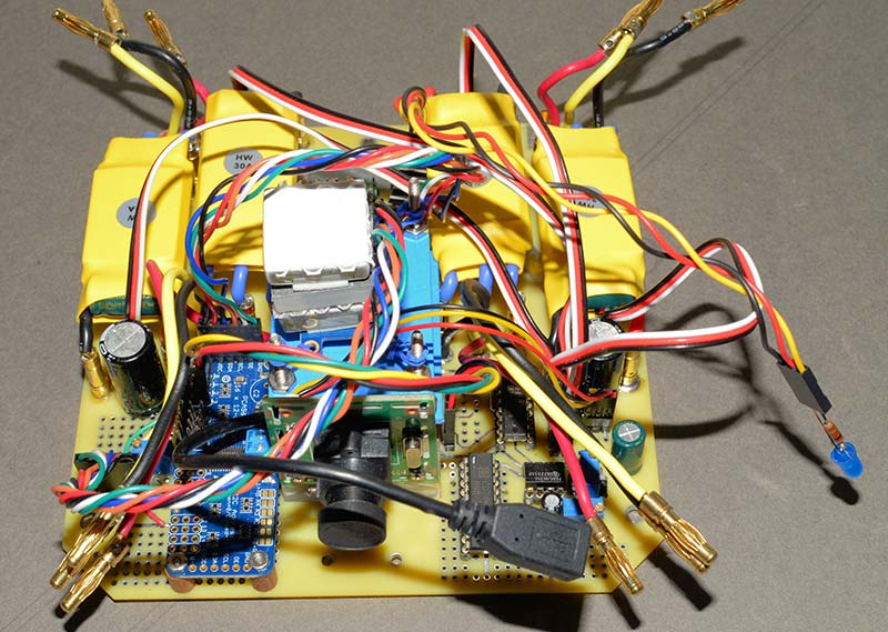
Figure 14. View of the PCB from the front.
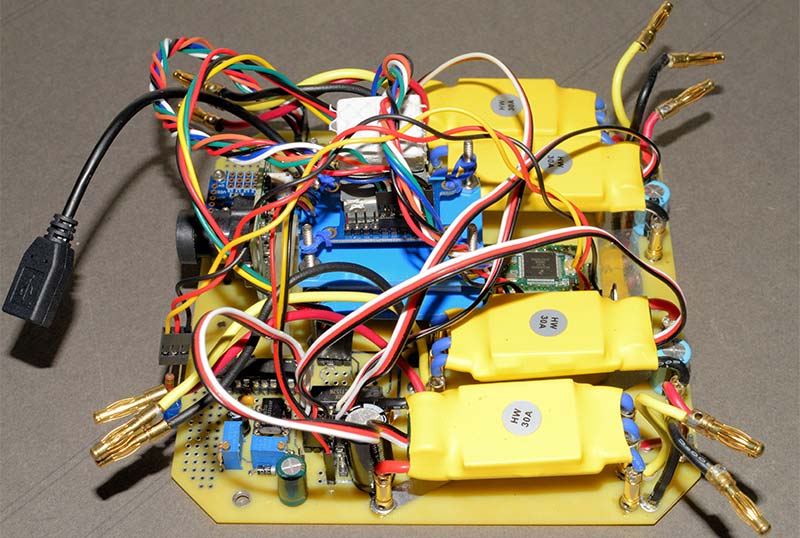
Figure 15. View of the PCB from the left side.
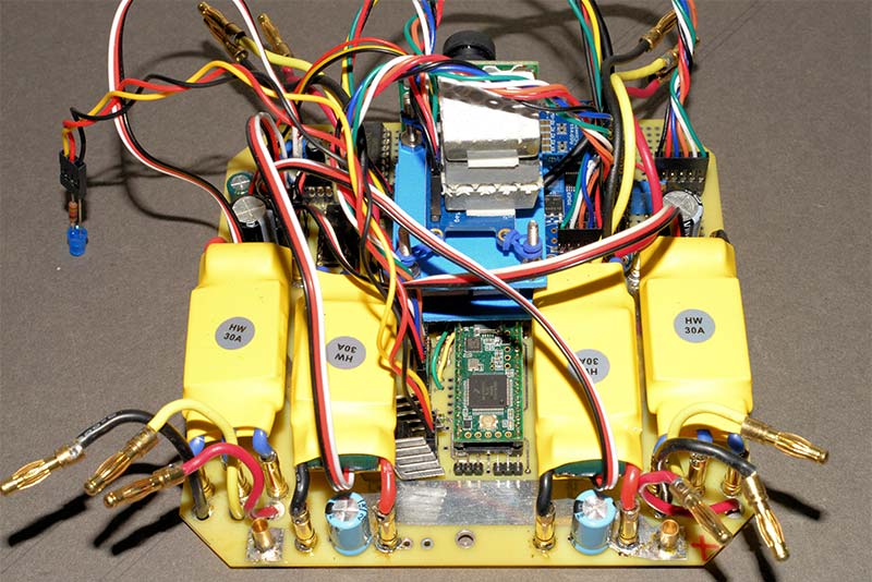
Figure 16. View of the PCB from the back.
The tangle of wires was difficult to work with. The four- and six-pin jumpers used were 20 centimeters long, and the full length of the servo cable on the ESCs was not reduced in length. Shorter jumpers would have helped.
The three short power leads from the ESCs with bullet connector ends worked quite well with each set of three in a corner near the female bullet connectors epoxied into the box corners.
Joystick Controller
For a period of time, I considered using a Playstation Dualshock 4 controller. It has the two joysticks that are needed, as well as a large number of other buttons that could be assigned special tasks. Plus, it’s ergonomic. However, this adds a whole additional layer of interface and programming complexity to the interface.
Using two simple miniature joysticks — each incorporating a single switch that will be read by an Arduino Nano — is a much simpler solution. The Arduino Nano reading the joysticks will talk directly to the Teensy 3.1 in the Quad_ROV through 50 feet of twisted pair. Additionally, it was easy to add an LCD display to the controller box for data display and feedback.
The circuit for the joysticks was mounted in a plastic project box measuring 200 x 120 x 75 millimeters (Figures 17 and 18).
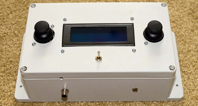
Figure 17. Joystick controller box.
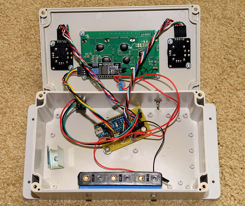
Figure 18. Inside the joystick controller box.
This is large enough to mount the two joysticks and have room for a 20x4 character LCD display.
The circuit for reading the joysticks is fairly simple (Figure 19).
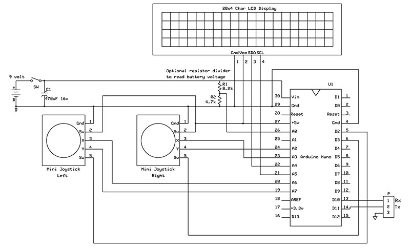
Figure 19. Schematic of the joystick controller.
The LCD display comes with an I2C interface, making connection to the Arduino very easy. The first version of the joystick controller software was written to read the joysticks and then send the data to the controller board in the Quad_ROV, and write the data values to the LCD. Later — because of intermittent loose connections on the headers on the controller board — the data was first sent to the controller board, and then the controller board echoed the data back to the joystick controller board which then displayed it on the LCD (Figure 20).
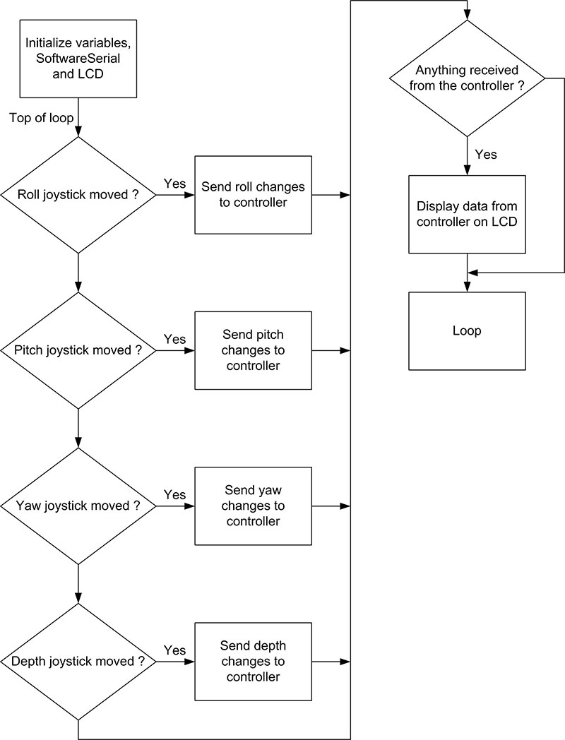
Figure 20. Flowchart of the joystick controller software.
By echoing the data back to the joystick controller, there is assurance that the data was received correctly. While a nine volt battery clip appears in Figure 18, this was later replaced by six AA batteries which provide longer battery life.The 19200 baud serial signal sent by the joystick controller is a five volt signal. The Teensy 3.1 can only output a 3.3 volt signal.
To bring the Teensy 3.1 serial signal up to five volts, the output line was passed though one of the bus transceiver lines of the 74LS245.
That’s a Wrap
This ends the first installment. The basics of construction have been covered, so next time, we'll begin with an improved PCB design and circuit.
We'll also cover the PID controllers, the software running the Quad_ROV, some suggestions for improvements, and a Parts List. The PCB layout and all software can be found in the downloads. SV
Calibrating the ESCs
The instructions that came with the ESCs described how to calibrate them using a radio control transmitter (as when doing this for a traditional quadcopter). Here is my translation for doing it, demonstrated with a simple Teensy 3.1 program.
Figure A is the circuit to be used with this program.
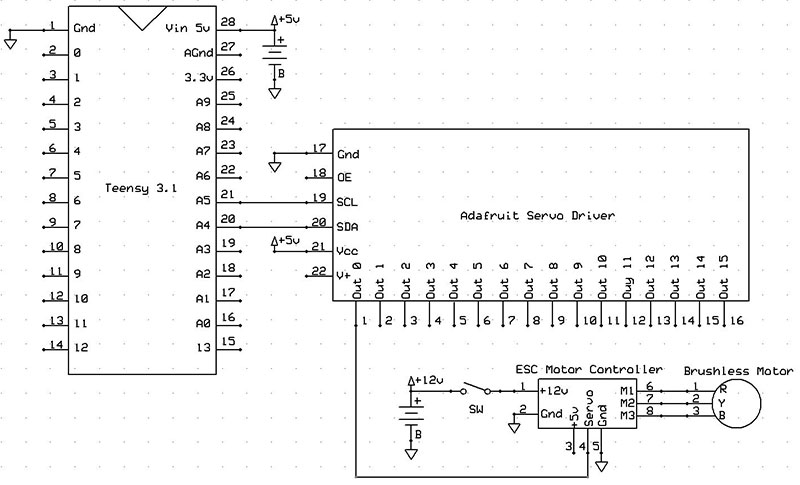
Figure A. ESC calibration circuit.
Be sure to connect a brushless motor to the ESC as that's what creates the output tones. Do not connect the 12 volts to the ESC until the program outputs "Connect 12 volts to ESC."
// Quad_ROV_Calibration
// This program calibrates one to four ESC
// units
// Written by Theron Wierenga, September 2017
// Note that this program uses the Adafruit
// Servo Driver Board
// Define the maximum and minimum values to use
// in calibration
#define MAX_SIGNAL 375 // This = 2005 uSec
#define MIN_SIGNAL 188 // This = 1005 uSec
// Include the needed libraries
#include <Wire.h>
#include <Adafruit_PWMServoDriver.h>
// Called this way, it uses the default address
// 0x40
Adafruit_PWMServoDriver pwm = Adafruit_PWMServoDriver();
void setup()
{
Serial.begin(115200);
Serial.println("Starting");
pinMode(13, OUTPUT);
// Setup PWM
pwm.begin();
pwm.setPWMFreq(50);
// Analog servos run at ~50 Hz updates
pwm.setPWM(0, 0, MAX_SIGNAL);
// Set outputs 0 - 4 to max throttle
pwm.setPWM(1, 0, MAX_SIGNAL);
pwm.setPWM(2, 0, MAX_SIGNAL);
pwm.setPWM(3, 0, MAX_SIGNAL);
Serial.println("Sending MAX_SIGNAL");
digitalWrite(13, HIGH);
// LED on denotes Teensy or Arduino sending
// MAX_SIGNAL
delay(3000);
Serial.println("Connect 12 volts to ESC");
Serial.println("Should hear a BEEP BEEP
signal");
delay(7000);
digitalWrite(13, LOW);
// LED off denotes Teensy or Arduino sending
// MIN_SIGNAL
pwm.setPWM(0, 0, MIN_SIGNAL);
// Set outputs 0 - 4 to min throttle
pwm.setPWM(1, 0, MIN_SIGNAL);
pwm.setPWM(2, 0, MIN_SIGNAL);
pwm.setPWM(3, 0, MIN_SIGNAL);
Serial.println("Sending MIN_SIGNAL");
Serial.println("Should hear several BEEP BEEPs for battery size, then LONG BEEP if success");
delay(7000);
while(true) {} // Loop forever, remove wires
}
void loop()
{
}
Article Comments