The ROV Manatee - Part 1
By Theron Wierenga View In Digital Edition
Build Your Own Remotely Operated Underwater Vehicle — Part 1: Construction
Having lived near the water most of my life and with manatees showing up regularly in the water nearby where we live in Florida, I developed an interest in having an ROV (Remotely Operated Vehicle) to video sea life underwater. Purchasing an ROV can be expensive, so after several prototypes, I successfully constructed an ROV from easily acquired parts that can be assembled with basic tools. Calling this project my ROV Manatee seemed appropriate.
The Challenges of and Solutions for Watertight Builds
Engineering your own ROV has construction challenges beyond designing and building the necessary electronics. The electronics package for the design is housed inside a six inch PVC pipe, with a tether cable running topside to a joystick steering mechanism. The tether is Cat5 cable and must enter the PVC pipe through a watertight seal. Additionally, the wires from the motors and optional light must also feed into the PVC pipe to connect to the motor drivers.
The integrity of these watertight connections is an absolute must as any water leak can be catastrophic to the electronics inside. My simple solution was to drill holes in the six inch PVC and then use marine epoxy to glue a 1/2 inch PVC coupling that is threaded on the inside. The wires are then pulled through a hole drilled in a 1/2 inch PVC threaded plug, after coating each wire with marine epoxy. The entire plug is then filled with additional marine epoxy. It is important that each wire going through the hole in the PVC plug have an epoxy coat around it before bundling them and passing them through the hole. The PVC plug is wrapped with Teflon™ tape and screwed tightly into the coupling.
A second challenge is achieving neutral buoyancy for the ROV, as well as a balanced trim. The six inch PVC tube and the 1/2 inch PVC frame act as floats, while the total weight of the ROV acts to sink it. These two must be balanced so that the ROV attains neutral buoyancy, where it simply hovers and does not sink or float to the top. This ROV needed additional weight.
After struggling with several ideas, the solution was a 14 inch square of ceramic tile, cemented to the bottom of the frame with bathtub caulk along with several smaller four inch square pieces. To fine-tune the buoyancy, a small petcock was added at the top and bottom of the frame. With the ROV just barely floating, these petcocks can be opened allowing a little water to enter the frame and adding weight. Adjusting how much water is in the frame can achieve near neutral buoyancy.
The trim of the ROV must be level; the position of the ballast is used to attain this. The height of the left and right motors must also match the vertical center of mass of the ROV. This allows the motors to push the ROV in a level direction. For example, if the motors are mounted too low, their thrust would tip the bottom of the ROV forward causing the ROV to ascend.
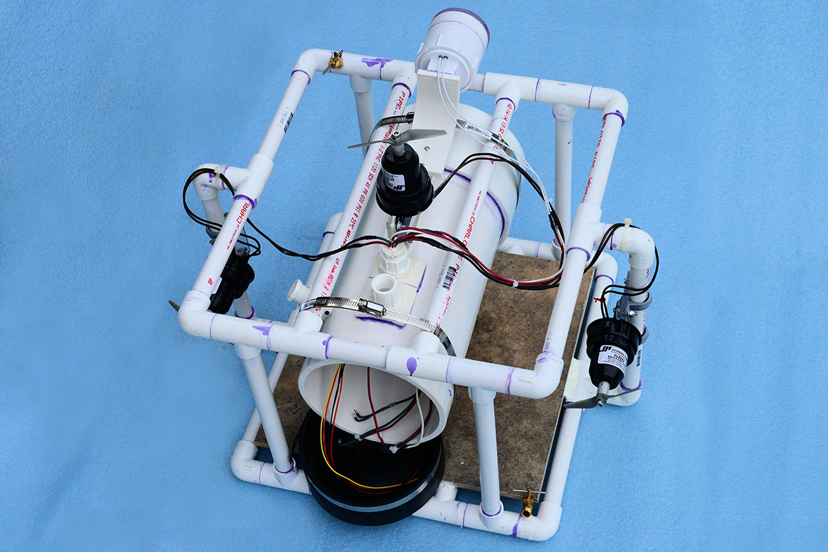
FIGURE 2. The PVC frame with the electronics package removed.
Three 500 gallon/hour bilge pump replacement motors are used to drive the ROV. A right and left motor facing forward provide forward, reverse, left, and right movement. A single vertically mounted motor on top of the six inch PVC pipe allows up and down movement. The motors are driven by H-bridge motor drivers capable of handling the higher current needed by the motors.
Four inch model airplane propellers were attached to the motor shafts. The couplers to attach the propellers to the motors were made from 1/2 inch aluminum rod with a hole drilled to fit the motor shaft, and are held in place with a set screw on the side. The propellers were attached to the other end of the coupler by an Allen head screw that goes into a threaded hole on the face of the rod. These can be made using a small drill press, but I used a small metal lathe to center the shaft and screw holes. Model boat propellers would probably have been a better choice, and the custom couplings would not have been necessary. The model airplane propellers were available, and they seem to work well.
The bilge pump motors are 12 volt and rated at 2.5 amps maximum. However, that rating is for running them as a bilge pump with the manufacturer’s pump impeller. After attaching a four inch propeller to one of the motors, it was tested by running it in a five gallon pail of water. It drew six amps from a 12 volt lead acid battery because of the load the propeller creates. This is something to remember when choosing a motor driver.
In addition, these motors cannot be run continuously at this higher current. For the most part, the motors are not run at full power, and are turned on and off continuously while the ROV is steered. The submersion of the motors in water does help to dissipate some heat, but it needs to be remembered that the motors are being overloaded at full voltage and can overheat.
The Process for Controlling the Motors
Two Arduino Nano microcontrollers are used for control: one topside to read the joysticks and one in the six inch PVC tube that houses the underwater electronics. A small game controller type joystick mounted in a plastic box was selected to control the speed and direction of the left and right motors. A linear potentiometer was used to control the up/down motor with center position being the motor off, and the up or down distance from center selects the direction and power for the motor. The Arduino Nano reads the joystick and linear potentiometer, and then — based on their positions — generates commands which it sends to the Nano in the ROV.
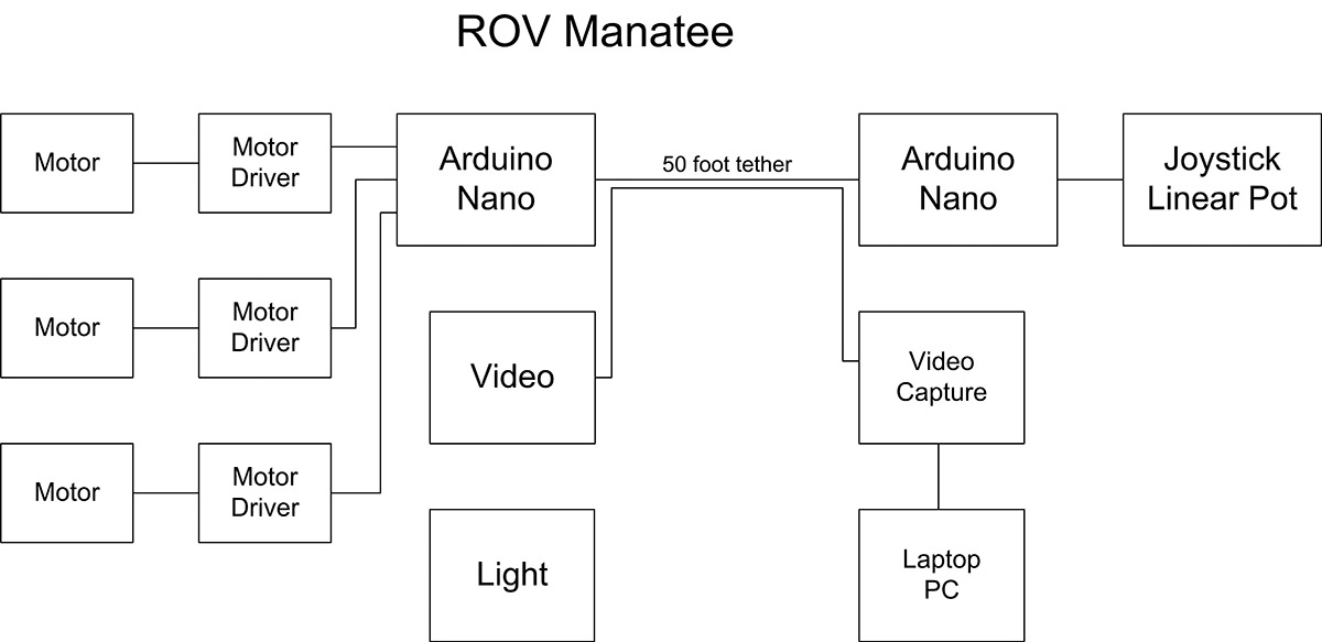
FIGURE 1. Block diagram of the basic electronics.
The commands for the motors consist of three letters followed by the three digits of an eight-bit number which is the PWM (Pulse Width Modulation) value. They are:
- LMF255 — Left motor forward and PWM value
- LMR255 — Left motor reverse and PWM value
- RMF255 — Right motor forward and PWM value
- RMR255 — Right motor reverse and PWM value
- UMU255 — Up/down motor up and PWM value
- UMD255 — Up/down motor down and PWM value
So, a command like LMF000 will turn the left motor off; LMF128 will run the left motor forward at half power; and LMR255 will run the left motor in reverse at full power. The forward/reverse and left/right values read from the joystick are run through a simple wheelchair algorithm which smoothes out the power changes as the joystick is moved.
These six-character commands are sent over two Arduino digital pins using the SoftwareSerial library. Assigned transmit and receive pins on the Arduino are hardwired through the tether to their opposites on the second Arduino. The ROV Arduino receives the six-character command and enables the specified motor and sets the PWM, which is then fed to the motor driver. The motor driver acts as a slave and powers the appropriate motor.
The circuitry in the ROV can also send data back up the tether to be viewed. Given that there is a large battery in the ROV running the motors, it is useful to be able to check on its voltage and how much charge is available. A simple two-resistor voltage divider can be read by an analog pin on the Arduino and — with a little math — converted into the battery voltage. Additional possible sensors are a depth gauge, compass, accelerometer, and gyroscope. Each piece of data can be coded in a fashion similar to the commands. For example, BAT followed by battery voltage as a float, CMP followed by 359, compass bearing going clockwise, and so on.
Construction of the Frame and Main Tube
The frame is made from 1/2 inch schedule 40 PVC pipe which is available in any home improvement store. The fittings used are 12 elbows and 20 tees. The uprights that the motors are mounted on were extended outward to give more room for the propellers, but this may have not been necessary. Additionally, the total height could have been reduced as extra room for ballast was not needed.
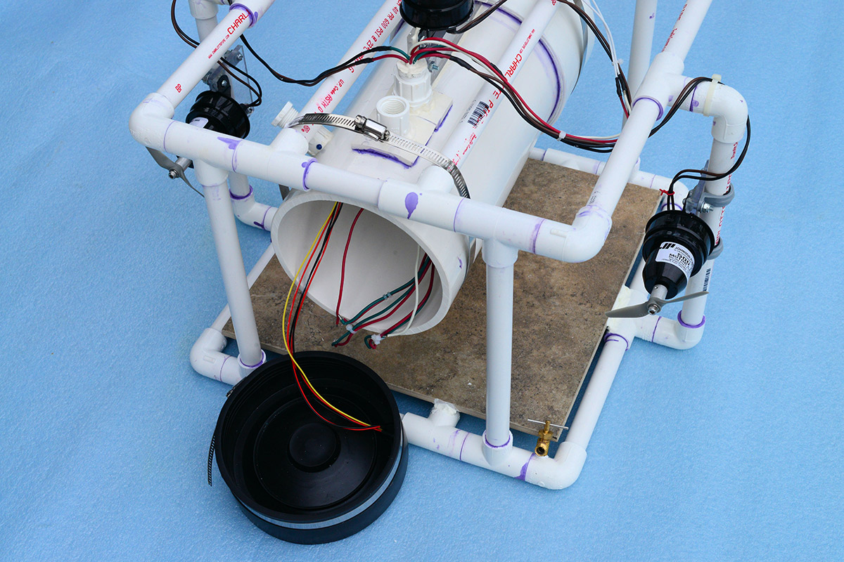
FIGURE 3. Back of the PVC frame with rubber end cap removed.
Using ceramic tile for ballast worked very well, and the height was perhaps not needed. In general, a cube shape of appropriate size is what works. Two brass petcocks were threaded into the 1/2 inch PVC tubes: one at the top and bottom. Opening these in the water allows you to very carefully trim the neutral buoyancy by adding a small amount of water into the frame.
The main tube has a six inch PVC cap on one end that’s attached with PVC cement. A 3-1/2 inch hole was drilled in the end of the cap, and a clear piece of 1/2 inch thick Plexiglas was cemented with marine epoxy over the opening to provide a window for the video camera. The opposite end requires an end cap that can be removed to insert the electronics. In the past, I have tried using a six inch coupling with one end threaded and then using a six inch threaded plug. Even with the use of Teflon tape around the threads, there was still some leakage. These large threads were made to have pipe-joint compound for a tight seal, which does not work well for ease of removal. Instead, I used a six inch black rubber cap sealed with a metal hose clamp; this has worked very well. The entire six inch tube is held in place underneath two 1/2 inch PVC cross pieces at the top by two eight inch band clamps.
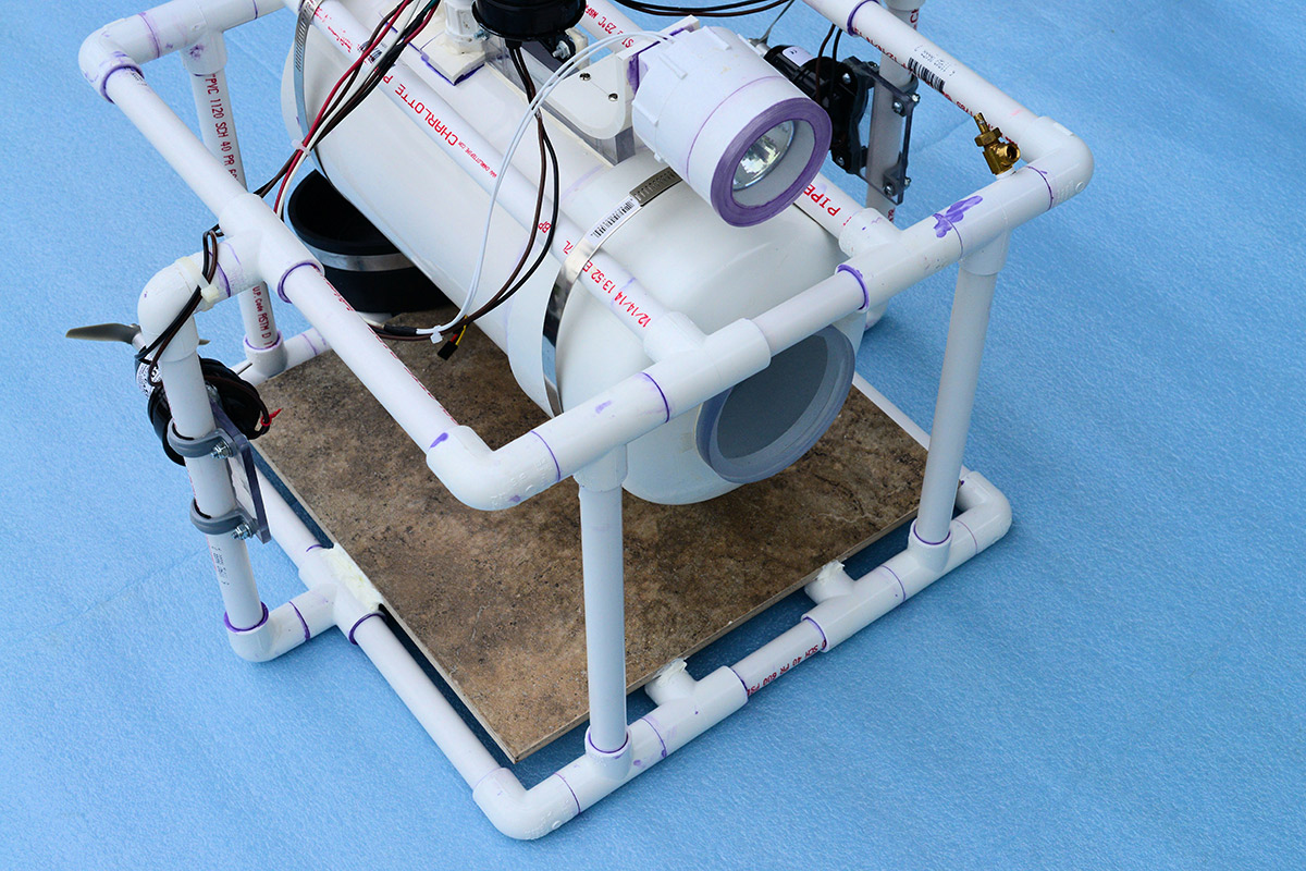
FIGURE 4. Front of the PVC frame showing headlight and camera window.
The top of the main tube has a 1/2 piece of Plexiglas vertically glued with marine epoxy for attachment of the up/down motor, and two 1/2 inch PVC threaded couplings also glued in with marine epoxy to receive the PVC plugs containing the wires feeding into the tube.
A Hall-effect switch was added with a third 1/2 inch PVC threaded coupling glued into the main tube. A Hall-effect switch and LED are potted into the coupling with marine epoxy. A 1/2 inch PVC plug with a Neodymium disk magnet cemented into it acts as the switch. When the plug is screwed into the coupling, it triggers a 12 volt 20 amp relay inside the main tube, activating the 12 volt circuitry. The relay contacts are wired in parallel with the main power switch. This allows power to be turned on and off without having to open the main tube. This circuit continuously draws about eight milliamps of current from the battery, which is not a problem for a 15 amp-hour battery.
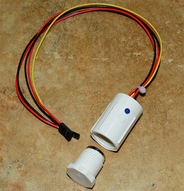
FIGURE 5. The Hall-effect switch and LED, with plug and attached magnet.
That’s all for this installment. Next time, we will cover the electronics package that reads the joystick and linear potentiometer, and then controls our motors. SV
Parts List
| Item | Description |
|---|---|
| A1 | Adafruit 9-DOF (Optional) |
| B1 | 12V 15AH |
| B2 | 9V Battery |
| BTS7960B | Motor Driver (3) |
| C1 | 1,000 µF, 16V |
| C2 | 2,700 µF, 6.3V |
| D1 | Blue LED |
| F1 | 18A Mini Circuit Breaker or Fuse |
| FL | Flood Lamp (Optional) |
| H1 | Hall-effect Switch 3144 |
| J1 | Three-pin Header |
| J2 | Three-pin Header |
| J3 | Three-pin Header |
| J4 | Four-pin Header |
| M1 | Left Motor, Johnson Pump 500 GPH |
| M2 | Right Motor, Johnson Pump 500 GPH |
| M3 | Up/Down Motor, Johnson Pump 500 GPH |
| P1 | Header Socket |
| P2 | Header Socket |
| Q1 | TIP127 PNP Darlington Transistor |
| R1 | 8.2K 1/4W Resistor |
| R2 | 4.7K 1/4W Resistor |
| R3 | 1K 1/4W Resistor |
| R4 | 1K 1/4W Resistor |
| R5 | 5K 1/4W Resistor |
| R6 | 5K 1/4W Resistor |
| R7 | 20K 1/4W Linear Potentiometer |
| R8 | 4.7K 1/4W Resistor |
| R9 | 8.2K 1/4W Resistor |
| R10 | 4.7K 1/4W Resistor |
| Relay | 12V 20A Contacts |
| Switch | 20A Contacts |
| Switch | Mini Toggle |
| U1 | Arduino Nano |
| U2 | Arduino Nano |
| U3 | LM7805 5V Regulator |
| Video Camera | NTSC |
| Miscellaneous 1/2 inch PVC Pipe 1/2 inch PVC Elbows 1/2 inch PVC Tees 1/2 inch PVC Threaded Couplings 1/2 inch PVC Threaded Plugs Six inch PVC Pipe Six inch PVC Pipe Cap Six inch Rubber End Cap, with Band Clamp 1/4 and 1/2 inch Plexiglas PVC Cement Marine Epoxy Silicon Cement Eight inch Band Clamps Nylon Cable Ties Various Screws, Nuts Hookup Wire Cat5 Cable, 50 feet Petcock Valves (2) Ceramic Tile |
|
Downloads
201603-Wierenga.zip
What’s in the zip?
Express PCB schematic and PCB files
Arduino Code Files
Article Comments