
Laser Alignment System for Your CNC Router
By Roger Secura View In Digital Edition
I really like simple solutions to problems. For example, I designed and built a desktop CNC router some time ago. Although it works as expected, I was wasting a lot of time trying to align the center of my tool bit with the corner edge of my workpiece (wood). Then, like a flash of light (no pun intended), it hit me — use a laser to find the edges of the wood. As it turns out, designing and building a laser system for my CNC router was really simple — just what I like.
WHAT TO EXPECT
In this article, I’ll show you how to build a laser power supply circuit and how to construct a special bracket for your CNC router motor. Figure 1 shows the kind of output you can expect from my laser system.
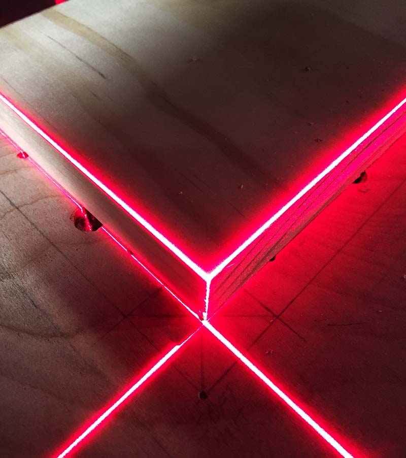
Figure 1.
You’re going to like the fact that the power supply circuit only requires three components: the LM317T voltage regulator and two resistors. If that sounds good to you, keep reading.
START WITH THE BRACKET
Figure 2 is the CAD drawing for the bracket that holds the two lasers in place.
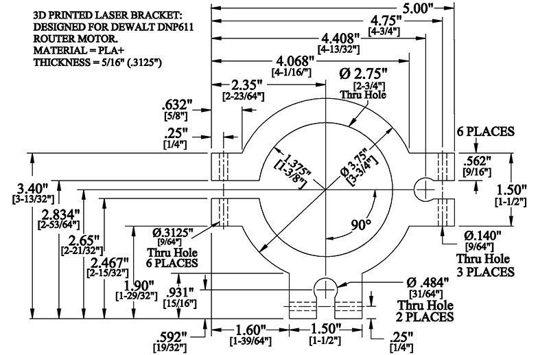
Figure 2.
Figure 3 is a photo of the bracket after it was printed on my Alfawise U30 3D printer.
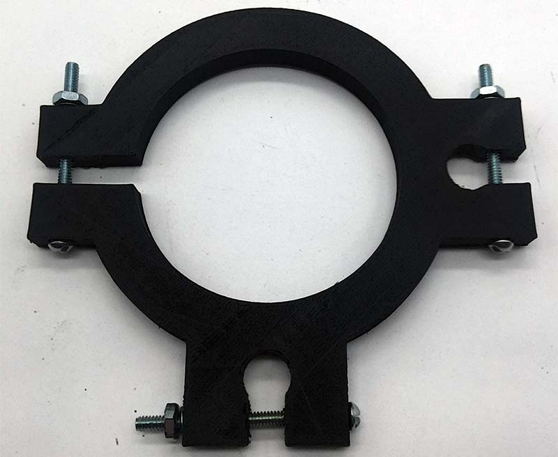
Figure 3.
Finally, Figure 4 shows the bracket mounted onto the CNC router motor.
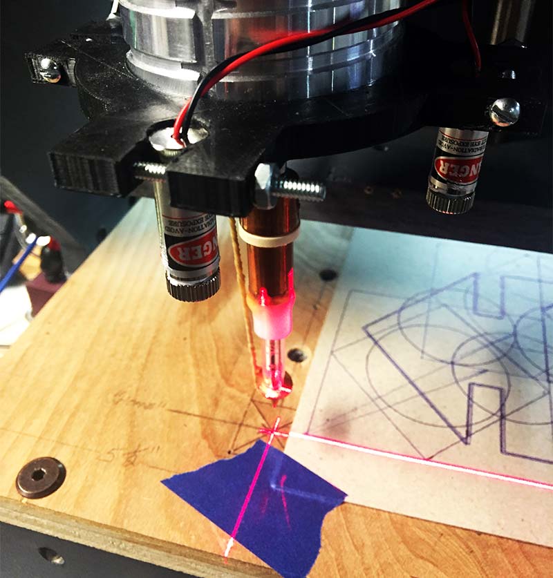
Figure 4.
Aligning and mounting the bracket is really simple. Draw (pencil) a temporary 90° angle on your router table so that each leg of the 90° angle is an equal distance from the edge of your table. Place a board in the corner of the angle. Now, slide the bracket onto the motor and lightly tighten the #6-32 machine screw. Rotate the two “line” lasers so they align themselves with the lower left-hand corner of the board as shown in Figure 1. Once aligned, level and tighten the bracket around the motor.
Now, using the two laser lines as a guide, it’s possible to center a router bit to any X and Y location on your table. For example, move your cutting tool to the Home position (Machine Zero). In the Offset screen in Mach 3, enter: X = 4; Y = 4. Now, hit the ‘Go to Zero’ button on the main screen in Mach 3. Once you reach the designation X = 4 / Y = 4, the lasers will show you where to put the corner of your workpiece.
Please note that this bracket was designed for my DeWalt DNP611 router. You may need to adjust the inner diameter (2.75”; see Figure 2) of the wooden bracket to fit your router or spindle motor. Be aware that in some cases, this bracket may interfere with the movement and/or travel limits of your Z axis.
Also, since both lasers have a focus adjustment screw on the front lens, you should unscrew the lens and add some Teflon tape (plumber’s tape) around the screw threads.
Apparently, the screw is too loose (bad design/manufacturing) to maintain a set focus point. Watch out for the spring inside the laser. It will pop out.
Finally, once you insert the 9/64” diameter mounting screws into the bracket, don’t over-tighten the screws. You could crack the bracket or the laser.
OKAY, LET’S POWER UP THE LASERS
As you can see in Figure 5, the circuitry required to power the lasers is quite simple.
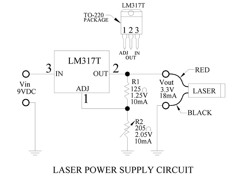
Figure 5.
I wanted to use 9V batteries, so I wouldn’t have to keep replacing them so often (like I would with AA batteries).
This requirement forced me to find a voltage regulator that could step down the voltage from nine volts to 3.3 volts — the laser’s operating voltage. Fortunately, the LM317T met my requirement and did so with just a couple of extra components — two resistors!
You’ll need to build two of these circuits; one for each laser. Get some general-purpose PC board (2-7/8” L x 1-7/8” W) and hard-wire the components as shown in Figure 6.
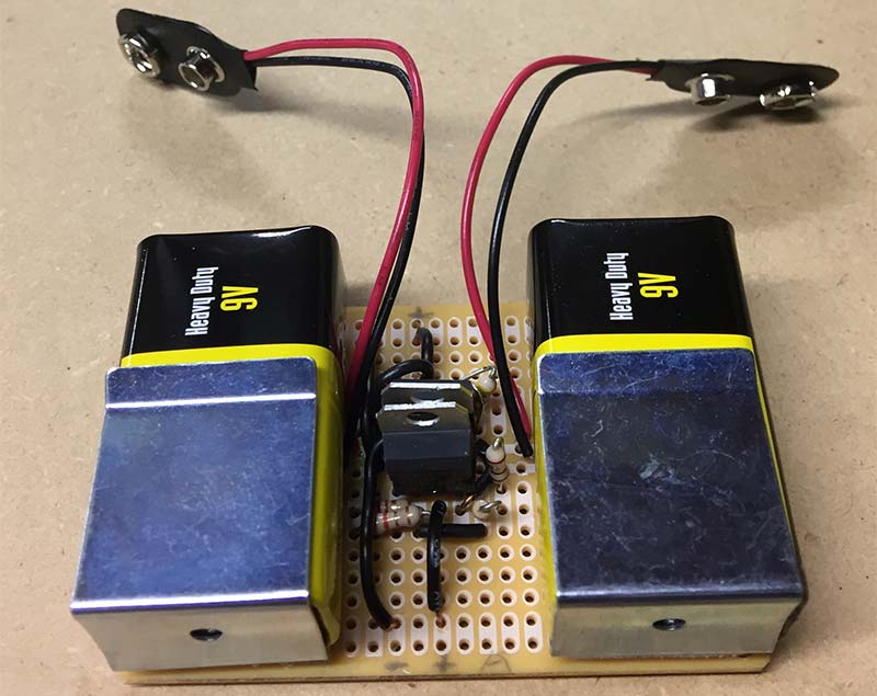
Figure 6.
You can glue or Velcro™ the battery clips to the perfboard. This makes it easy to replace the 9V batteries when they get low. Figure 7 shows the circuit board mounted onto the CNC machine.
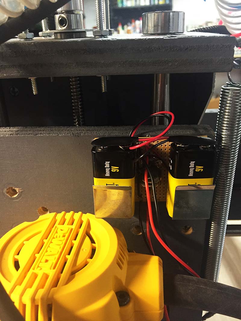
Figure 7.
HOW THE CIRCUIT WORKS
The LM317T voltage regulator is kind of amazing for what it can do. If you insert a potentiometer into the circuit (R2), you can vary the regulator’s output voltage (Vout) from 1.25V to 37V.
The uniqueness of the LM317T is that you only need to add two resistors to get any output voltage between 1.25V and 37V.
According to the datasheet, the LM317T must have a minimum of 10 mA flowing through resistor R1 or it falls out of regulation.
In addition, by design, the regulator will always have a constant “reference” voltage level of 1.25V across R1, measured from pin 2 to pin 1. In order to determine the resistor value for R1, we use Ohm’s Law as follows:
R1 = E/I
R1 = 1.25V/10 mA
R1 = 125 ohms
As you can see, the value for R1 is 125 ohms. Let’s verify the minimum required current running through R1 is 10 mA:
IR1 = E/R
IR1 = 1.25V/125 ohms
IR1 = 10 mA
Since the current running through R1 is 10 mA, the series circuit of R1 and R2 dictates that the same 10 mA must run through R2. To calculate the resistance value for R2, we use the following formula (use 3.3V as our desired output voltage for the laser):
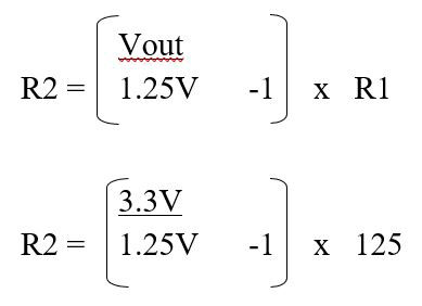
R2 = 205 ohms
Now, insert R1 (125 ohms) and R2 (205 ohms) into the circuit. Take a voltmeter and check the output voltage and verify that it’s 3.3V, measured from the Vout terminal to ground.
Notice that if we add the 1.25V across R1 and the 2.05V across R2, we get 3.3V at the Vout terminal. In other words, since the voltage across R1 (1.25V) never changes, we can control the output voltage at the Vout terminal (1.25V to 37V) just by varying the resistance of R2.
If you’d rather not do the math, you can just make R1 equal to 125 ohms and use a potentiometer for R2. Now, turn the pot (R2) until the desired output voltage (measured from Vout to ground) is acquired.
Remove the pot from your breadboard and check the ohm’s setting with an ohmmeter. Insert an equivalent resistor value back into the circuit.
Again, check the voltage level at the Vout terminal to verify that you have the required output voltage; 3.3 volts for example. Done!
Okay, now for a few caveats about the LM317T. First, the input supply voltage at pin 3 (Vin) MUST be a minimum of 2.5V to 3V higher than the output voltage (Vout). In other words, if you need 3.3V for Vout (load), Vin must be at least 6.3V. Failure to adhere to this rule will cause the LM317T to fall out of regulation.
The ‘minimum’ differential voltage between Vin and Vout is called the “drop-out” voltage (see the datasheet). If you go below the minimum (3V), the regulator stops working.
Secondly, the larger the voltage differential is between Vin and Vout, the more heat will be dissipated within the LM317T. It makes sense.
If, for example, you have a 12V supply coming into the regulator at pin 3 (Vin) and your Vout (load voltage) only requires 3.3V, the LM317T will have to dissipate the voltage differential (5.7V) as heat.
As a rule of thumb, the larger the differential, the more heat is generated. This means a heatsink may be required.
LASERS
The two lasers used in this project (and shown in Figure 8) are called “line” lasers.
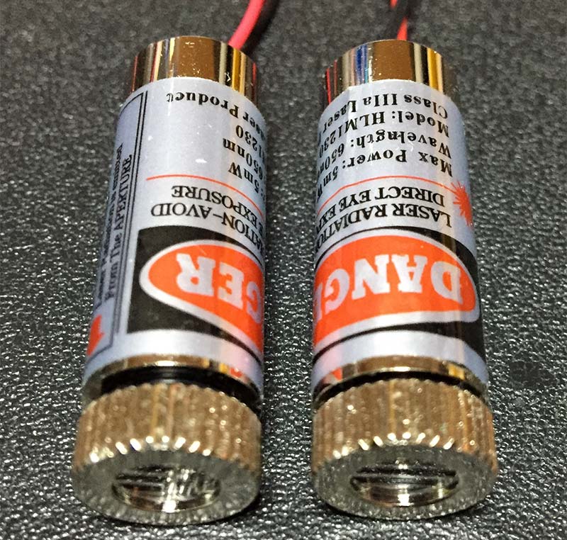
Figure 8.
In other words, you can buy lasers that project a single line, a cross pattern, or a dotted line pattern. Just be careful when buying your lasers online. Look for focusable 5 mW line lasers.
WARNING! WEAR EYE PROTECTION!
No project is worth damaging your eyesight. Any time you work with lasers, you need eye protection. Just remember, a laser beam reflected off a shiny surface could accidently target your eyes.
Please, don’t power-up your 5 mW lasers until you have read ‘Sam’s Laser FAQ’ at www.repairfaq.org/sam/lasersaf.htm.
The 5 mW lasers used in this article have a wavelength of 650 nm-660 nm. Therefore, before you buy a pair of safety goggles, drop by YouTube’s website and enter the following text into the Search Box: “Choosing Laser Goggles” and “Testing Laser Goggles.” Don’t buy those cheap goggles and damage your eyesight!
Spend the extra money and get a good pair of safety glasses. You’re worth it! SV
Parts List
| ITEM | QTY | DESCRIPTION | PART# | SOURCE |
| R1 | 1 | 125 ohm, 1/4W, 1%, Metal Film | 71-RM60D1250F | Mouser |
| R2 | 1 | 205 ohm, 1/4W, 1%, Metal Film | 71-CMF50205R00FHEB | Mouser |
| IC | 1 | Voltage Regulator, 1.25V-37V | 511-LM317T | Mouser |
| Laser | 2 | 650 nm, 5 mW, Red, Focusable, “Line” Laser with Driver, Working Voltage 3-5V, Dimensions 12 x 35 mm | 650ML-5-1235-2pcs-LM | Amazon |
| Goggles | 2 | Red, 635-660 nm Laser Protection | NYBG | Amazon |
| Perf Brd | 1 | General-Purpose Grid-Style PC Board | 276-150 | RadioShack |
| Screw | 3 | Machine, #6-32 x 1-3/4”, Phillips | n/a | Home Depot |
| Nut | 3 | #6-32 Machine Screw Nut | n/a | Home Depot |
| Washer | 3 | #6 Lock Washer | n/a | Home Depot |
| Battery | 2 | 9 VDC | n/a (optional) | |
| Bat Snaps | 2 | 9 VDC Battery Snaps & Contacts | 121-0526/I-GR | Mouser |
| Bat Clip | 2 | 9V Horizontal Battery Clip | 12BH071-GR | Mouser |
Article Comments