Hardware Hacking a Power Wheelchair Control Module
By Darby Hewitt View In Digital Edition
On the surface, using a power wheelchair as a robotic base seems like a no-brainer. The control modules for these chairs contain all of the necessary electronics to drive the motors, including DC/DC converters, PWM generation, and a microcontroller to govern acceleration, deceleration, and braking. Before I knew better, I purchased a power wheelchair thinking that it would be a simple task to wield the functionality of the electronics already built into the control module. However, as anyone who has attempted this knows, available documentation for wheelchair control modules is virtually non-existent.
As a result, all of the previously-reported wheelchair robots I read about online bypassed the original control module altogether, used separate PWM motor drivers, and typically disabled the electric brakes on the motors. These solutions work well, but I couldn’t force myself to abandon the well-designed control module that I had at my disposal just because the make-up of its guts was elusive.
Thus, began my experience of hacking a wheelchair control module.
The Beginning
This project began when one of my students approached me at the beginning of summer 2016 with the desire to create a robot that could roam around our department, talk to students, take pictures to post to a Twitter account, and ultimately provide a scalable robotic platform for students to build upon. Because this robot could be subjected to some wear-and-tear as a result of its frequent interaction with students and faculty, I immediately thought of using a power wheelchair as its base.
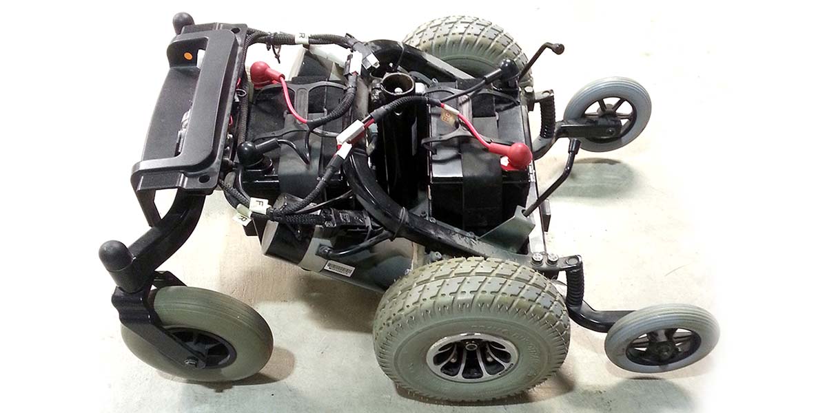
Relatively inexpensive power chairs are easy to find on eBay (if you are willing to go pick them up), and my student and I found one for $130 that was within driving distance: a Pride Jet 3, with a Penny+Giles Pride control module (see Figure 1). Once we purchased new batteries (for another $120), we thought we were in business, but the conversion from chair to robot was a bit more challenging than we first anticipated.
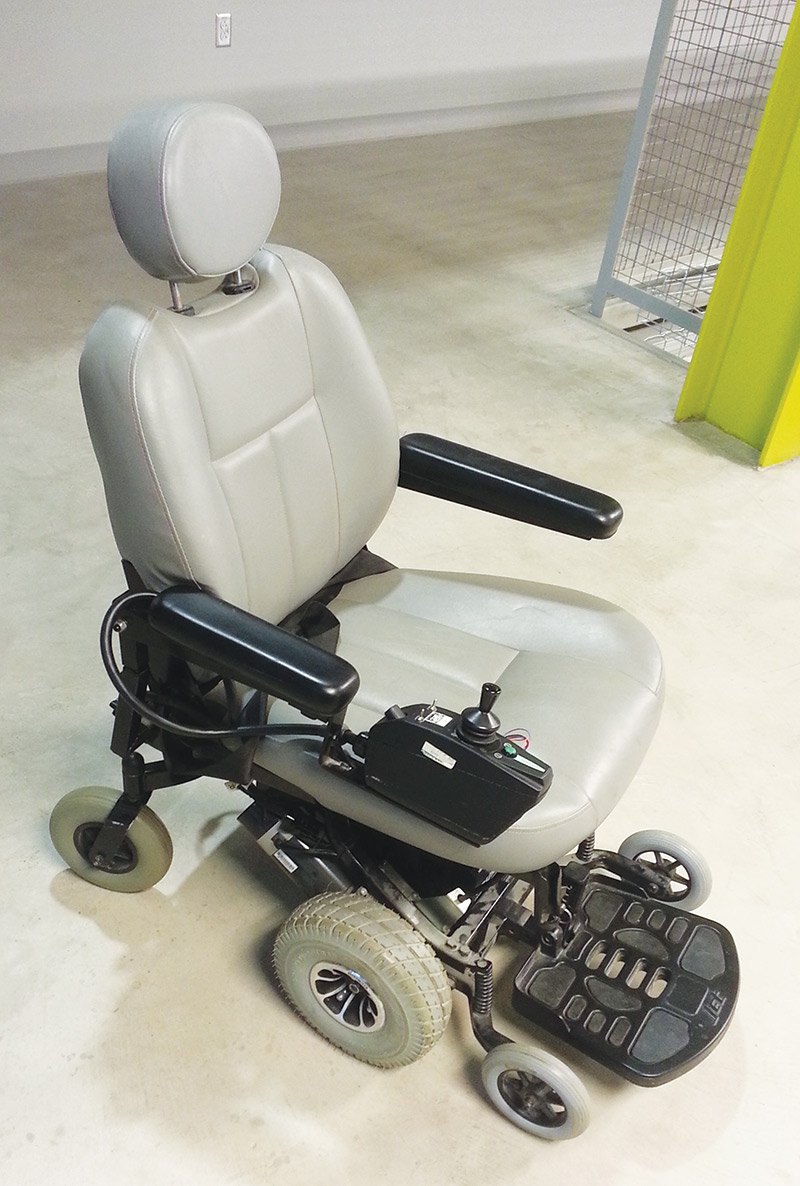
FIGURE 1. The Pride Jet 3 power chair I found on eBay.
Opening the Module and Fomulating a Game Plan
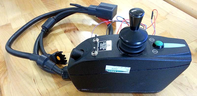
We started by taking a look under the hood of the control module, which — again — amazingly houses all of the electronics for power, motor driving, and electric brake control. The photo in Figure 2 shows an inside view of the control module. It may be difficult to tell, but the module is tightly packed; there is hardly any unused space inside.
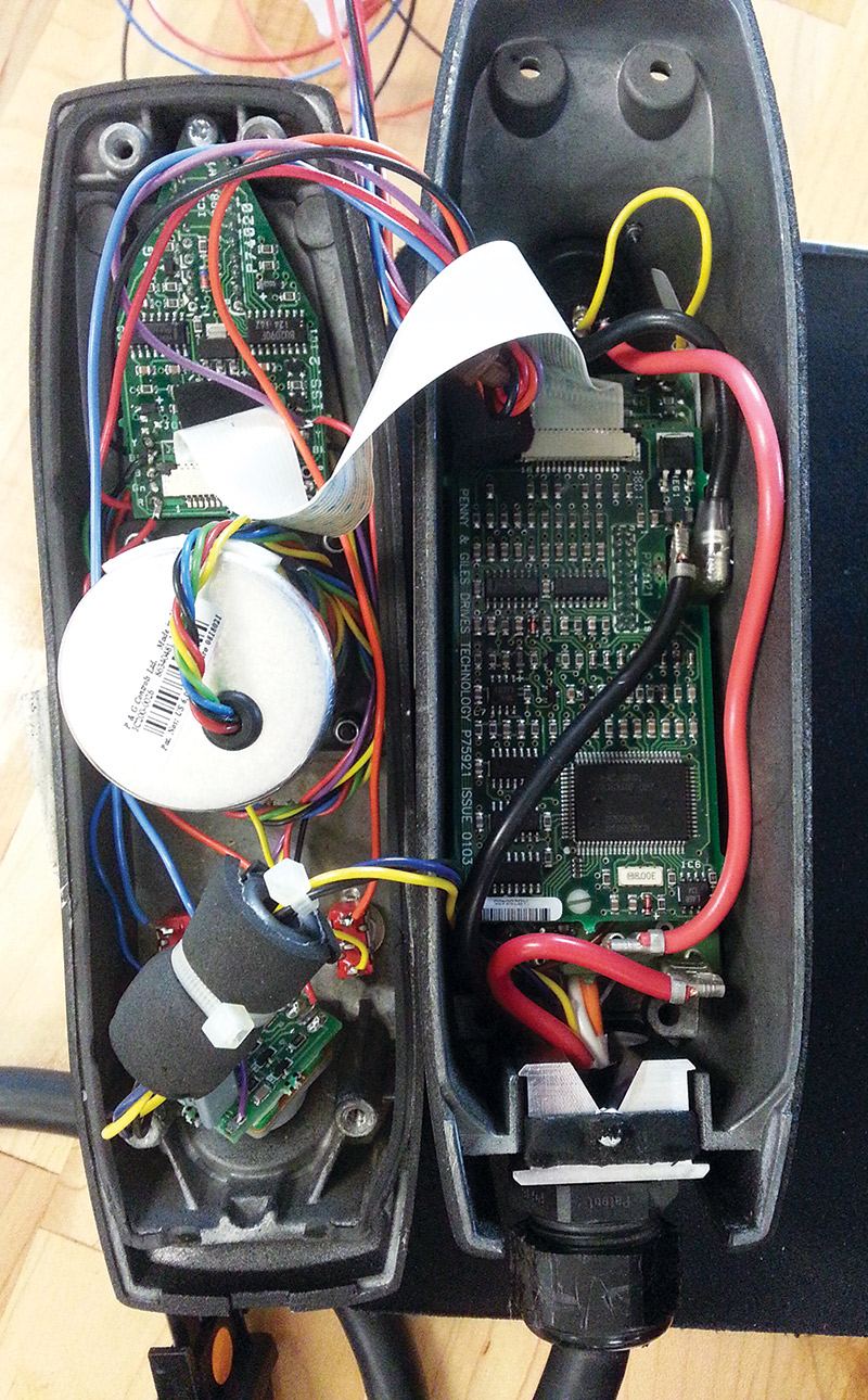
FIGURE 2. Inside view of the Penny+Giles Pride control module that came with my used power chair.
The top of the box holds the bargraph power indicator, the power button, and the joystick, along with several PCBs (printed circuit boards) which serve to interface these components to the rest of the module via a ribbon cable and a bundle of two small wires.
The dense packing of the electronics in the module was overwhelming at first. However, since the joystick is the most direct way of controlling the motion of the chair, that seemed like the most logical place to begin our investigation of the inner workings of the control module. The joystick module itself is housed in a metallic cylinder (shown prominently in Figure 2) which is mounted on the top of the control module. A bundle of five different colored (black, green, red, yellow, and blue) wires connects this module to the rest of the electronics in the box. Each of these wires fortuitously connects to a solder pad on the PCB that houses the power button and the LED indicator bargraph. Using these pads as contact points, we were able to determine the purpose of each of these wires through the use of a digital multimeter (DMM).
Our initial guess (which turned out to be correct) was that the black wire provided a circuit ground connection for the joystick module. So, we connected the ground lead of our DMM to the black wire and probed the voltages of the other wires with respect to that node. We found that the red wire was held at a constant 12V, and that the green wire was held at a constant 6V with respect to the black wire. The voltages of the other two wires varied according to the motion of the joystick.
When the stick was at rest, both the blue and yellow wires were held at 6V. However, when the joystick was rocked from fully backward to fully forward, the voltage of the yellow wire varied smoothly from 5V to 7V. Similarly, when the joystick was rocked from left to right, the voltage of the blue wire varied smoothly from 5V to 7V.
Discovering the behavior of the yellow and blue wires was a breakthrough in the wheelchair hacking process; all it takes to harness the power of the chair is to emulate the behavior of these two wires. If we could figure out a way to control these two analog voltages using a standard digital platform, we knew we would be in business.
Digital Generation of Analog Voltages: First Steps and Mishaps
Generating and low pass filtering pulse width modulated (PWM) digital signals is a common technique for generating analog output signals from a digital device, and when analog output is needed from a microcontroller platform without a built-in DAC (digital-to-analog converter) peripheral (such as the ATmega328P at the heart of the Arduino Uno, for example), this is often the most logical choice. Things can get complicated, however, when the voltages involved don’t lie within the 0-5V range.
Also, even after filtering PWM signals with a capacitor, there can be some residual high frequency noise that rides on top of the resulting analog output signal. In this case, since I knew we were going to need to (at least) provide an offset voltage for a filtered PWM ouput signal and I wasn’t sure how sensitive the control module would be to noisy control voltages, I scrapped the idea of PWM in favor of a more elegant and platform-agnostic solution.
The easiest, quickest, and least reliable way to create a variable voltage is through the use of a voltage divider. A voltage divider is nothing more than a series of resistances across which a voltage is applied. Figure 3 shows a schematic of the simplest form of a voltage divider: two resistors in series.
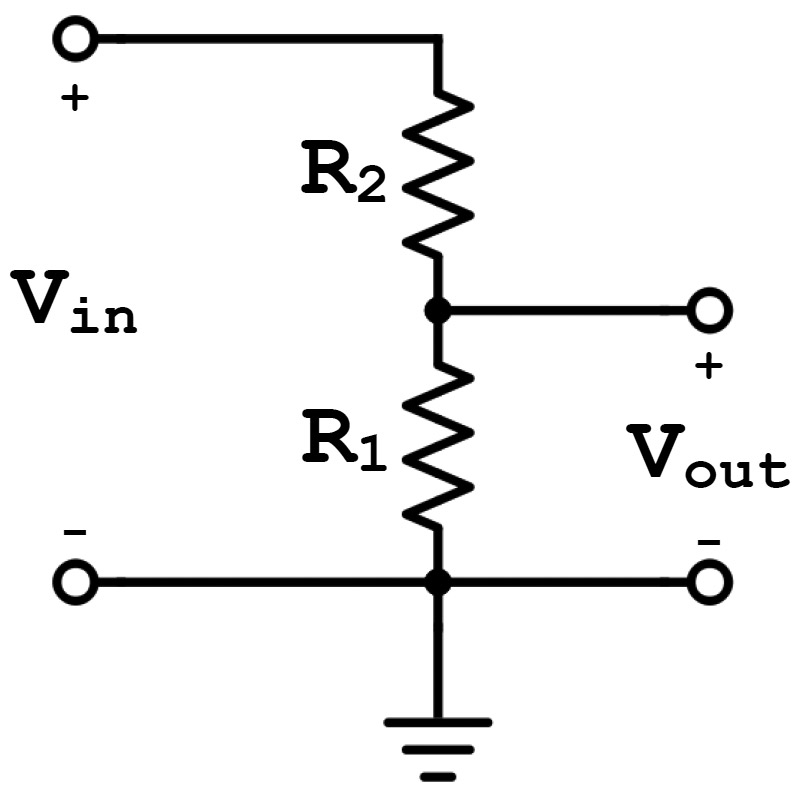
FIGURE 3. Schematic of a simple voltage divider with two resistances.
In this circuit, the output voltage is related to the input voltage and the resistors according to the relationship:
This equation is known as the voltage divider rule. I won’t bore you by proving that it works; if you have doubts, Google it.
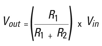
My first thought when designing the circuit for these control lines was to use a voltage divider with two resistors and a potentiometer (shown in Figure 4) to generate the 5-7V range needed for each channel. Voltage dividers do not provide stable voltages when they are loaded down (as would be the case if — for example — I was going to try to drive a DC motor between the output voltage from this circuit and ground), but if they are used to provide a voltage to a high impedance input (which I correctly assumed was the case for this control module), then they are sufficiently stable in most cases. So far, so good.
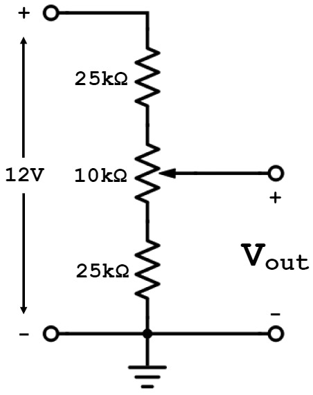
FIGURE 4. Schematic of a slightly more complicated variable voltage divider with three resistances, one of which is a potentiometer. The output voltage from this circuit is in the range of 5-7V.
At this point, I just needed to find a digitally controllable potentiometer to place in my circuit of Figure 4 that could interface easily with a digital platform. There are many devices out there that seem like they would fit in this circuit just like a mechanical potentiometer would, but I learned the hard way that digital pots are not always as flexible as their physically tangible counterparts.
I chose to use a Microchip MCP4251 for my circuit (the datasheet is available in the downloads). The MCP4251 is a dual-channel SPI-controllable digital potentiometer which comes in 5, 10, 50, and 100 kW varieties. I chose to use the 10 kW version, of course, in light of the resistance values I had used in Figure 4.
Using my trusty protoboard, I wired up this simple voltage divider, and I wrote some quick-and-dirty Arduino code to communicate with the potentiometer via SPI and vary the output voltage sinusoidally. Then, I connected the output voltage to my oscilloscope, turned on the power, and watched the screen. Nothing happened.
At first, I assumed my problem was related to the SPI commands I was sending. (Did I misread the datasheet?) After double- and triple-checking, I decided that the commands should work. To check this conclusion in another way, I disconnected the voltage divider from the power supply, set my DMM to resistance mode, and started checking the resistive properties of the digital multimeter.
The resistance across the entire device was measured at 10 kW. So far, so good. Next, I checked the resistance between the wiper and one of the ends of the pot. I saw a large oscillating variation from 0 to 10 kW. At this point, I was stumped. The potentiometer was behaving exactly as I expected, and yet the output voltage from my circuit was not varying when the power supply was connected.
It didn’t take too much digging into the datasheet for the MCP4251 to discover my mistake. The voltage applied to the wipers of these digital potentiometers must be between Vss (0V in my circuit) and Vdd + 0.3V (5.3V in my circuit). In contrast, I had attempted to apply 5V and 7V to the ends of the potentiometer.
Rats! It was time to modify my initial circuit.
The Solution: Another Simple Circuit to the Rescue
Since I was able to vary the wiper position of my digital pot as desired, I knew that this device could still be useful in my final design. I could easily create a voltage divider to provide a variable 0-2V output voltage by applying 5V across a 15 kW resistor connected in series with my 10 kW pot, as shown schematically in Figure 5. Prototyping this circuit was a breeze, and it produced the desired results.

FIGURE 5. Schematic of the variable voltage divider used in this project. The output voltage from this circuit is in the range of 0-2V.
Once this circuit was completed, I just needed to apply a 5V DC offset to its output, which I knew I could do with another simple circuit: a summing amplifier.
The schematic of a basic summing amplifier is shown in Figure 6.
FIGURE 6. Schematic of a simple summing amplifier circuit. The output voltage from this circuit is proportional to the weighted sum of the input voltages.
The output voltage from this amplifier is a weighted sum of the two input voltages, V1 and V2, defined according to the relationship:
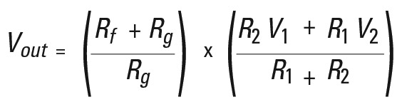
If all resistances in this circuit are equal, Vout = V1 + V2. Putting the voltage divider from Figure 5 together with this amplifier produced the circuit shown in Figure 7, where R1, R2, Rf, and Rg from the circuit of Figure 6 have been replaced by 10 kW resistors. This circuit ultimately produces a range of 5-7.7V at the output of the op-amp.
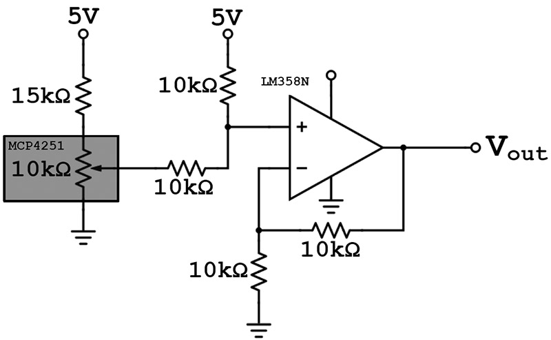
FIGURE 7. Schematic of the voltage divider from Figure 5 incorporated with a summing amplifier like that in Figure 6. This is the circuit used to control a single degree of freedom for the wheelchair robot. The digital potentiometer is boxed in gray.
We could increase the 10 kW resistances to bring the upper limit of the output voltage range closer to 7V, but we can easily circumvent this upper limit when we write software to control the wiper position for the pot, thus controlling the output voltage.
Given this solid design, we knew we just needed two of these circuits to take control of the translation and rotation of our power chair base.
Putting the Pieces Together and Warming Up the Soldering Iron
To realize this circuit in hardware, I used an LM358N IC (datasheet also available in the downloads) which is a single-source dual op-amp. Whereas op-amps typically require equal-amplitude positive and negative voltage sources with respect to circuit ground in order to function correctly, single-source op-amps allow for a single-ended power connection, as long as the output voltage remains between ground and +Vcc.
I chose this device because I knew I would be using these op-amps to produce a positive range of voltages, and I knew I would have easy access to the +12V power of the chair. Using my trusty breadboard, DC power supply, DMM, and some simple Arduino code (at the downloads), I built both channels of the circuit and successfully put each through its paces.
With a working prototype in hand, it was almost time to get out some protoboard and solder it up. First, however, some slight modding of the control module itself was in order. As I mentioned above, I needed to tap into the power of the chair in order to power my circuit. Also, I needed access to the two control lines from the joystick. Furthermore, I wanted to maintain the ability to put the chair back into manual control mode.
So, I mounted two SPDT switches in the housing of the control module: one for each channel. I desoldered the control lines from their pads on the power button PCB, and resoldered them to the switches. I then soldered wires from the center taps of each of the switches to the pads originally directly connected to the control lines. At this point, I had the ability to disengage the control lines completely.
The last step in modifying the control module was to connect several leads to the power and control lines of interest so they could be accessed outside the box. I drilled a small hole in the side and passed five wires out of the module: the two joystick control lines (connected via the open terminals of the two toggle switches), 12V and ground (0V) connections, and also a regulated 4.8V connection (just in case), which I found while poking around with my DMM.
Finally, I placed IC sockets and resistors in place on my protoboard and soldered the circuit together, connecting the 12V, ground, and control lines in their appropriate places. While a number of digital devices could be used to control the wheelchair through this circuit, I chose to initially use a Raspberry Pi. Given the fairly substantial current requirements of the Pi, I decided to also incorporate an L7805 5V 1.5A DC/DC regulator on the board to tap 5V off of the 12V supply from the chair.
This seemed like a safer bet for powering the Pi than using the 4.8V connection I found, since I wasn’t sure how much power I could eek out of this regulated voltage from the chair, and I knew that the Pi really requires 5V at a minimum anyway.
It Works! What’s Next?
The ultimate result of all of this work is shown in Figure 8.
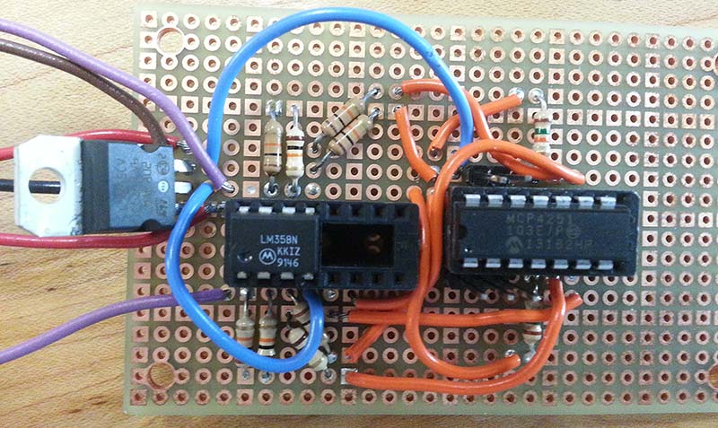
FIGURE 8. The prototype, soldered together on perfboard. It's not pretty, but it works!
Admittedly, I was rushing to get a quick-and-dirty prototype together, and while the board looks ugly, it works great. One of my not-too-distant goals is to rebuild this circuit on a Raspberry Pi prototyping HAT, so it will sit rigidly on the Pi rather than being tethered by a bundle of wires.
As for software to control the resulting robot, we have created a simple Python class to represent the robot and to encapsulate its motion capabilities (see Robot.py in the Github repository at https://github.com/ACURobotics/darbot-code.git). My plan is to transition to using the Robot Operating System (ROS) on the Pi to provide a nice software platform for expanding this robot’s functionality.
This project has resulted in a sturdy reconfigurable platform that can be unleashed on a crowd without worrying about it getting broken. My hope is that it can be used to conduct robotics research (in addition to taking pictures at department events).
Ultimately, we invested under $500 for the chair, batteries, electronic components, and Raspberry Pi, and with some basic knowledge of electric circuits we were able to turn that investment into something awesome. SV
Article Comments