
CNC Routers: The Z Axis Zero Setter
By Roger Secura View In Digital Edition
If you’re a newcomer to the world of CNC routers, one of the many tools you should have on hand is a Z axis zero setter (a.k.a., touch plate). A zero setter will improve the accuracy of your machine, reduce tool breakage, and save your workpiece from damage.
In this article, we’ll look at why you need a Z axis zero setter, and how to use one to establish the location of “part zero.”
“PART ZERO” WHERE ARE YOU?
The part zero location tells the CNC controller software (Mach3, for example) where on the workpiece (X, Y, Z) the g-code program should begin the cutting process (see Figure 1).
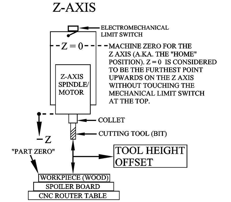
FIGURE 1.
Before we take a look at some of those methods, let’s go through two common scenarios to demonstrate why you need some way (a tool) to establish the location of part zero.
Scenario #1
You’ve clamped down a piece of wood onto your CNC router table in order to make a sign. Let’s say your cutting tool is sticking out of the collet (it’s actually called “stickout”) exactly 1.00”. Everything is going fine until the tool bit suddenly breaks.
So, you replace the broken tool with another tool bit, but this time the tool bit is sticking out of the collet 1-1/8”.
Now, unless all your tool bits are somehow marked, it’s nearly impossible to manually change a cutting tool and have it stick out of the collet at the exact same length as the previous tool.
Consequently, when you go to restart the sign program (g-code) and resume the cutting process, the tool bit bores into the wood 1/8” deeper than the first tool bit — thereby ruining the sign.
In other words, your CNC control software wasn’t updated with the exact distance (height) from the bottom of the new tool bit to the top surface of your workpiece (wood).
Scenario #2
Let’s flip the situation upside down by changing the thickness of the workpiece to be cut rather than changing the stickout of the tool bit. You start out with a 1/4” thick piece of wood for your project. After a successful run of the first piece, you replace the 1/4” thick piece of wood with a 1/2” thick piece of wood.
Now, even though the tool bit stickout length hasn’t changed, the workpiece is sitting on the table 1/4 inch higher than the last piece. Consequently, the g-code will plunge the tool bit through the top of the 1/2” board to get to what it still “thinks” should be the top surface of the original 1/4” thick piece of wood.
Once again — as in Scenario #1 — the g-code had no idea that the distance from the bottom of the tool bit to the top surface of your workpiece had changed.
Conclusion
If you change the cutting tool and/or change the thickness of your workpiece, you must employ some method to find the exact “Tool Height Offset” (THO). In other words, the user must somehow update the g-code with the exact distance (height in inches) from the bottom edge of the tool bit to the top surface of your workpiece. Take a look at Figure 1 again.
THERE’S A METHOD TO THE MADNESS
One of the most common ways CNC hobbyists establish a THO — and therefore part zero — is with the “paper” method. The trick is to place a thin piece of paper (a Post-it, for example) on the top surface of the workpiece (see Figure 2).

FIGURE 2.
Next, starting at the top of the Z axis (“machine zero”), the cutting tool is slowly lowered towards the top of the paper. Now, as the bottom edge of the tool bit gets close to the paper, the user stops all Z axis movement and switches the router’s Jog mode to “Step” (one thousandth of an inch per step — .001”). Now, as the operator continues to lower the Z axis, the paper is manually moved back and forth until the tool bit stops the paper from moving. As a last step in the procedure, the user will clear the Digital Read-Out (DRO) display for the Z axis (Z=0).
The operator has now established the “part zero” location for the Z axis (i.e., top surface of the workpiece).
If the paper is thin enough (cigarette paper, for example), the user will just zero the Z axis once the tool bit touches the top surface of the paper. In turn, g-code like Mach3 will set the top of the paper as the current part zero position. This is usually close enough.
THE Z AXIS ZERO SETTER METHOD
Unfortunately, the paper method is both time-consuming and inaccurate. This is an area where a zero setter can really help.
Another method used by hobbyists to determine the THO is to replace the piece of paper with a Z axis zero setter (see Figure 3). You can pick one of these up on Amazon for less than $10.
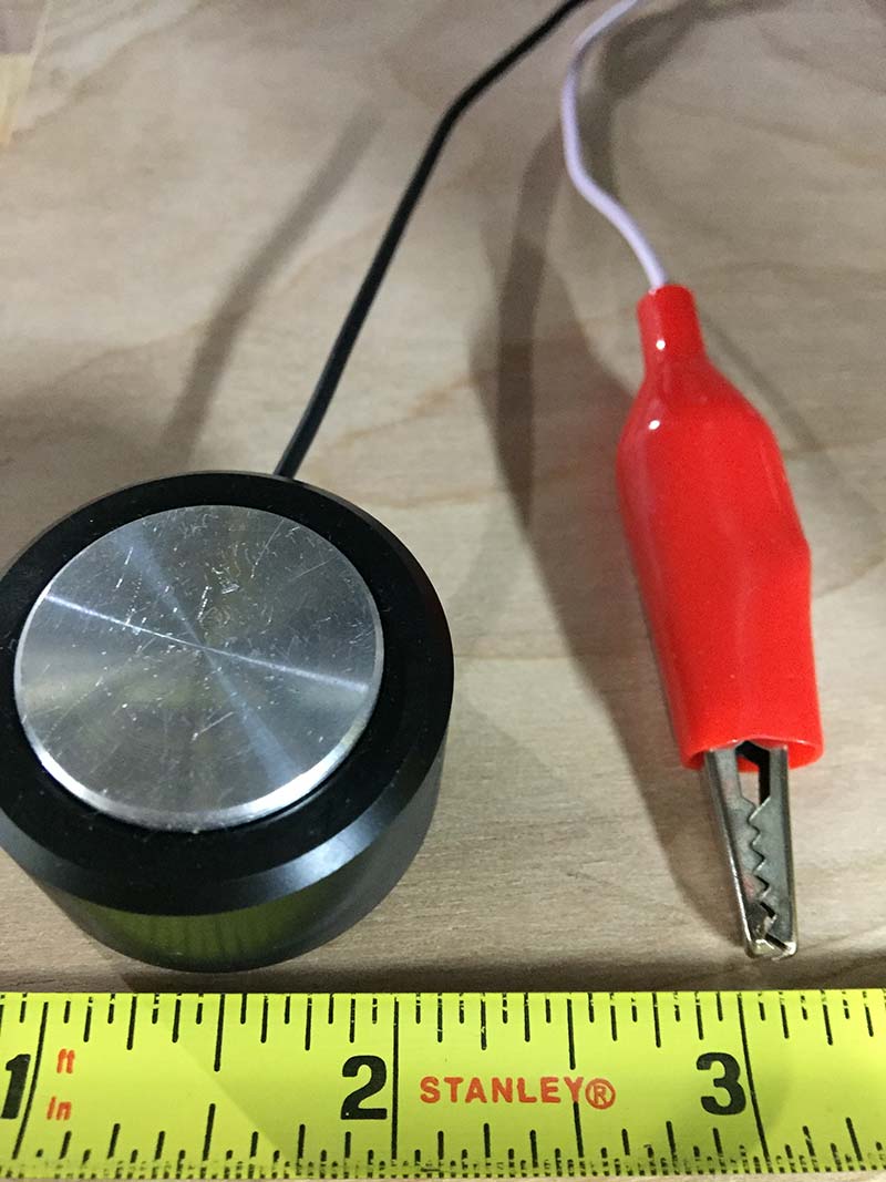
FIGURE 3.
Using a zero setter removes the time-consuming task of fettling with a piece of paper by automating the entire process through a Visual Basic (VB) script program.
The only problem with utilizing the VB script program is the user has to modify the program in order to set up his/her particular zero setter (thickness). With so many versions of the VB script program online, it can be confusing for someone just getting started with CNC routers.
[Note: You’ll find many versions of the VB script program online. Unfortunately, because of a copyright infringement issue, I decided not to include any example programs in this article. Don’t worry! I’ve included my own g-code program here and as a download, so you don’t need to hunt for any VB script programs.]
Here’s how the VB script works. The user lowers the tool bit to approximately 1/2” above the Z axis tool setter. Next, the VB script is executed and does the following to establish the THO: The tool bit is lowered towards the top of the tool setter at a very low “feed rate” (5-10%).
Once the bottom of the tool bit touches the top of the tool setter the tool bit automatically stops moving, then retracts itself upwards to a preset distance (1.00”).
In turn, the VB script will use the point where the tool bit touched the top of the zero setter and the zero setter’s height (thickness) to update the Z axis DRO with the exact THO.
Once again, just like with the paper method, the zero setter method has established the part zero location for the Z axis (i.e., top of workpiece).
“I DID IT MY WAY”
Although both methods mentioned above work very well, I prefer a modified version of the Z axis zero setter method.
My method allows me to skip the paper and VB script program by running a very short g-code program (seven lines) I created. After I run the program, I just add two negative numbers together and enter that sum into the Z axis DRO box (Offset screen — G-54 in Mach3) — done!
Let’s run through how to set up, test, and run my version of the zero setter method.
First, verify (digital calipers) and record (pencil and paper) the exact height (thickness) of your tool setter.
Next, set up the zero setter. Grab an alligator clip and attach it to the cutting tool (bit). Now, take the white wire from the alligator clip and connect it to the ground terminal on your controller board.
The black wire coming out of the round zero setter goes to one of your controller’s input terminals; it may be labeled “Probe” (check your manual).
On the ‘Ports and Pins’ screen (see Figure 4) in Mach3, find the word Probe from the list and enable it with a check mark. Also, enter the port number — usually 1 — and check Active Low.
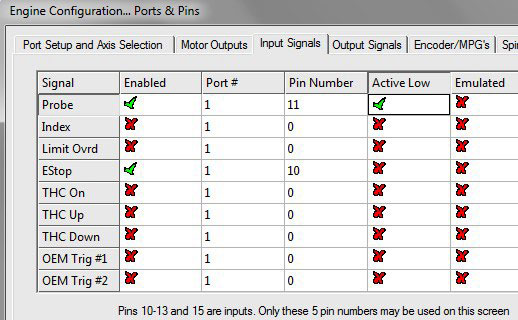
FIGURE 4.
Now, go to the Offsets screen (see Figure 5) and set the Z axis for the G54 offset to zero. Hit the Enter key and then click the Save Offsets button.
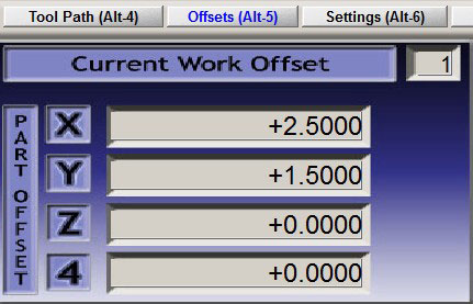
FIGURE 5.
Next, open Notepad and type in the g-code program shown in Figure 6.

FIGURE 6.
It’s the seven lines of g-code at the bottom (N100 to N700). Make sure you hit the Enter key after the end of line N700 M30. Save the file as xxxx.nc (for example, Tsetter.nc).
Now, load the program into your g-code.
MANDATORY TEST
Move the Z axis upwards to its “Home” position (machine zero). Now, to verify that the zero setter wiring setup is working correctly, raise the zero setter up to the bottom edge of the tool bit as shown in Figure 7.
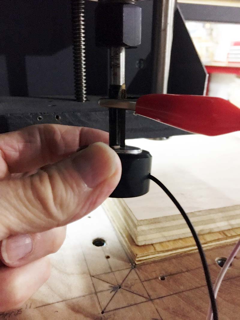
FIGURE 7.
On the Diagnostic screen in Mach3, you should see a green LED light up next to the box labeled Digitize when you touch the zero setter to the bottom edge of the tool bit (see Figure 8).
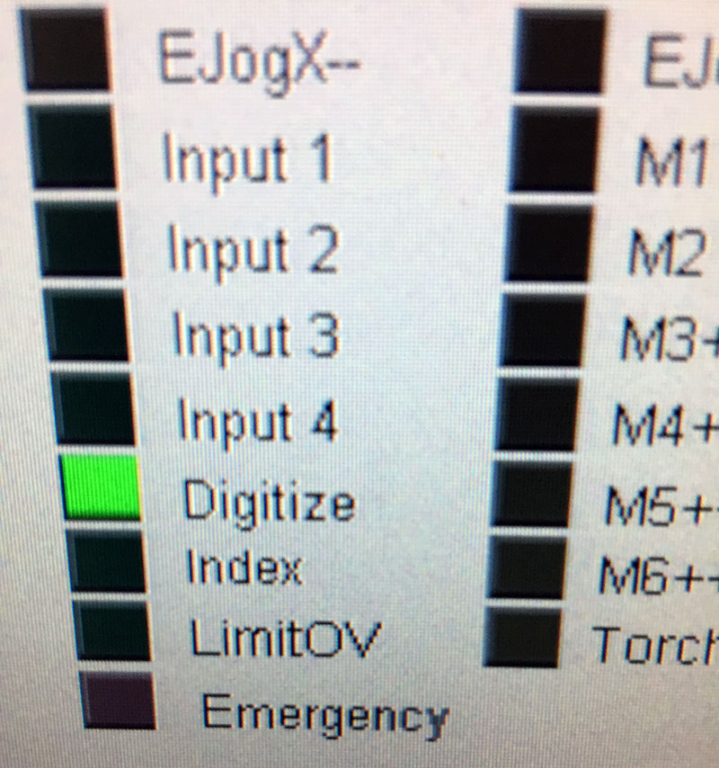
FIGURE 8.
(WARNING: Failure to do this test could damage your CNC router, or worse, injure you by crashing the tool bit into the metal zero setter. This test procedure MUST be repeated every time you use the zero setter; in other words, whenever you change a tool bit and/or the thickness of your workpiece.)
If you verified that the Digitize LED is working (green light), place the zero setter on top of your workpiece (wood).
Move the X and Y axes so the cutting tool is hovering over the center of the zero setter. It’s also important that you return the Z axis to its machine zero position (top of the Z axis).
Next, run the g-code program. Keep a finger on the emergency stop button (E-stop) just in case.
Once the bottom of the tool bit touches the top surface of the zero setter and stops, you have 15 seconds to write down the negative number displayed for the Z axis (Mach 3 — Main screen) before the program raises the Z axis back up to machine zero (Z=0).
Now, add that negative number to the height/thickness of your zero setter. Make the zero setter height number negative too.
Next, go to the Offsets screen in Mach3 and enter the sum of the two negative numbers into the Z axis DRO box. Hit the Enter key and click the Save Work Offsets button. The ‘negative’ number you enter in the Z axis box is the THO. In other words, it’s the exact distance (inches) from the bottom edge of the tool bit to the top surface of your workpiece (i.e., part zero for the Z axis). Refer back to Figure 1.
The final step is to verify that everything works by returning the router to its Home position (machine zero: X=0, Y=0, Z=0), and then hit the ‘Go to Zero’ button located on the Main screen in Mach3. Again, have a finger ready on the E-stop button.
This will send your X and Y axes directly over the lower left-hand corner of your workpiece — assuming you set up a Work Offset (G54) for the X and Y axes (for example, X=2.5, Y=1.5).
If you followed all the procedures correctly, your CNC control program will automatically move (Z axis) the bottom edge of the tool bit downward to the lower left-hand corner of your workpiece and stop.
This point is your part zero location. It’s also your Work Offset (G54) location (for example, X=2.5, Y=1.5, Z= -2.59). The -2.59 number is the THO for the Z axis.
FINAL NOTES
Here’s a problem I had and the solution I found that may help you. After successfully running my zero setter program, I couldn’t figure out why my cutting tool was digging just a little bit too deep into the top surface of my workpiece.
Fortunately, I decided to rerun my ‘Steps Per Unit’ procedure for the Z axis in Mach3. Well, guess what ... the Z axis was off by .012” — problem solved!
It’s always a good thing to get into the habit of “Homing” (a.k.a., machine zero, X=0, Y=0, Z=0) your CNC router right after loading your CNC control software. This lets the operator and control software know where the cutting tool is stationed in relationship to the total working area of the table (bed).
Remember, all X, Y, and Z coordinates on your machine (work offsets, part zero, soft limit switches, etc.) are referenced (measured) from the Home position.
Finally, if you’re new to the world of CNC routers and are confused about the terms machine zero, work offset, part zero, and program zero, be sure to read my article here. In it, I explain all the above terms in great detail. SV
Article Comments