Avoiding Obstacles while Following a Line with the Scribbler 3
By John Blankenship View In Digital Edition
Many people know that Parallax’s Scribbler 3 robot can draw pictures with precise movements because of its wheel encoders. However, the Scribbler’s IR and line sensors along with access to a hacker port provide capabilities that make it a contender for more mainstream robotic projects. That algorithm will be explained in detail, so you can make other robots perform these tasks even if you don’t own a Scribbler.
In a previous article, Carol Lynn Hazlett demonstrated the Scribbler’s ability to make very precise movements. While such precision is impressive for drawing (letting the robot live up to its namesake), it’s generally not necessary for autonomous sensor-driven behaviors. In fact, it’s easy to assume that a robot known for its ability to draw might not be worthy of conventional robotic projects.
As you will see, such predispositions are unfounded. The truth is that the Scribbler 3 (S3) is an inexpensive fully-assembled robot with many capabilities that are worthy of your consideration.
The purpose of this article is to spotlight those capabilities and demonstrate how easily they can be implemented using a version of the BlocklyProp language developed specifically for the Scribbler.
Available Sensors
The Scribbler has many sensors, but those used in this article are two infrared units to detect objects in front of the robot and two reflective sensors for following a line.
These alone are enough for some interesting projects, but the S3 BlocklyProp language has built-in support for servomotors and PING))) ultrasonic sensors connected to the hacker port (which provides six digital I/O lines and two A/D pins).
For this article, a small servomotor will act as a rotating turret for the PING))) to provide ranging data.
Adding the Turret
Figure 1 shows how easy it is to add a ranging turret to the S3.
![]()
Figure 1.
The main body of the servomotor was hot-glued to the back of a PING))) sensor, and a four-pin header was hot-glued to the servomotor’s output shaft.
This allows the turret to be mounted by simply plugging it into the solderless breadboard also shown in the figure. The breadboard was attached to the S3 using double-sided tape.
Note also that the servomotor and the PING))) are connected to the S3 hacker port (which also supplies both 5V and 3.3V to power external sensors). Figure 2 shows the turret mounted on the S3 in its operating position.
![]()
Figure 2.
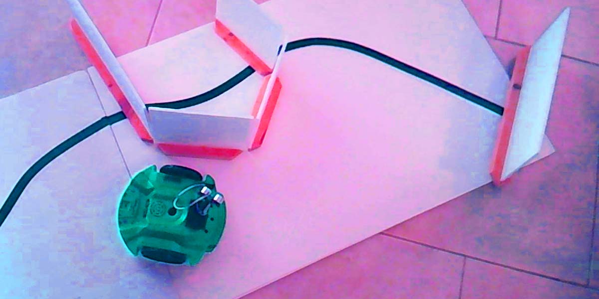
I wanted a project that would demonstrate not only the PING))) turret, but also the line and IR sensors. Figure 3 shows what I came up with.
![]()
Figure 3.
The S3 will use its line sensors to follow the line shown, starting from the left side.
While following the line, the S3’s IR sensors will be utilized to detect objects blocking the path. When an object is detected, the turret will be pointed forward and the PING))) data used to move the S3 until it is two inches from the obstacle.
At that point, the S3 will reorient itself in preparation to follow the contour of the object until it finds the line again. It does this by turning the turret to the left and using the PING))) to maintain a fixed distance from the wall.
The line sensors will be monitored during the line following, and when the line is detected, the S3 will reorient again, this time preparing to resume the line following behavior.
The S3 will continue following the line until it finds a second obstacle before terminating the program.
Everything could have been done with only the PING))) turret and the line sensors, but this approach also demonstrates how to use the IR sensors (which have the advantage of providing detection data faster than obtaining range information from the PING)))).
The Program
Figure 4 shows the main portion of the program used to implement this project.
![]()
Figure 4.
It starts by setting up three speed variables that will be used to control the robot’s movements throughout the program. The servomotor is then positioned directly forward.
You would expect this to be 90°, but my servo and mounting required a parameter of 80 to be pointed directly forward.
An IF statement in Figure 4 allows the main functions to be executed only if the reset button on the S3 is pressed. This allows the user to start the program by pressing this button.
The four user-defined functions shown then make the robot perform the following tasks:
- Follow the line until the path is blocked by an obstacle.
- Prepare to circumnavigate the object by following its contour.
- Hug the object’s contour until the line is seen again.
- Prepare to follow the line by aligning with it.
- Follow the line again until the path is blocked by an obstacle.
Let’s look at each of these modules individually to see how they work. Figure 5 shows the FollowLineTillBlocked module. It begins by moving the turret to its forward position.
![]()
Figure 5.
Next, a loop continues as long as an obstacle is not detected by the IR sensors. Inside the loop, an IF statement gently turns the robot right or left depending on the state of the line sensors.
You can control how fast the robot turns by experimenting with the speed parameters mentioned earlier.
Figure 6 shows how the robot orients itself to prepare for the wall following behavior.
![]()
Figure 6.
The IR sensors can detect objects 8-10 inches away, so we need to move the robot closer to the object blocking the path before attempting to follow its contour.
A loop does this by moving the robot forward as long as its distance from the object is greater than two inches. The robot then is rotated to the right 70° to align it with the wall. It will still be facing the wall a little, but that is preferred over facing away from the wall.
Figure 7 shows the wall following routine.
![]()
Figure 7.
It starts by pointing the turret to the left (and slightly forward) to obtain the distance to the wall slightly in front of the robot (which enhances the wall following performance).
A loop then turns the robot away from the wall when it gets too close, and toward the wall if it is too far away. This action continues until the line sensors detect a line.
Figure 8 explains how the robot prepares to follow the line again. It starts by moving forward two inches to get itself over the line.
![]()
Figure 8.
Then, it rotates right until the line sensors indicate it is properly positioned.
The last function call in Figure 4 simply calls the FollowLineTillBlocked module a second time to follow the line until an obstacle is detected before terminating the program.
As you can see, BlocklyProp makes it easy to implement line following and obstacle avoidance behaviors on the S3.
I’m hopeful that support will soon be added for the Parallax compass and background serial communication with user-definable pins.
Such additions are already available on other Parallax products and would make even more advanced behaviors possible with the Scribbler 3. SV
Article Comments