An ARDUINO CONTROLLED ROBOT ARM Part 2
By Ricardo Caja Calleja View In Digital Edition
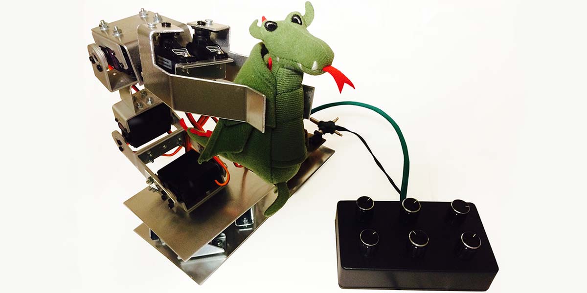
Last December, I showed how I had built my robot arm, describing the construction of the body, and the design and assembly of the hardware (electronic controller). In other words, I described the “physical” robot arm. So, now we have a robot arm fully assembled — which is pretty cool — but what can we do with it? Nothing yet! It still needs to be programmed in order to actually move and do other cooler stuff.
The robot arm can be controlled manually using the “control box” with rotating knobs (potentiometers) that was built in the first article, as well as through the serial port (USB and Bluetooth) from a PC, Raspberry Pi, smartphone, etc. The possibilities are almost infinite! Especially when it comes to software, the choices are countless: Processing, Matlab, Python, ROS, just to mention a few.
So, I had to keep my feet on the ground and choose specific software to start with. Read on to find out the details!
Operation Modes
Although I’ve already been experimenting with Bluetooth connectivity, for now we’ll focus on robot arm control using a PC via USB. I’ll come back to the serial communication via Bluetooth towards the end of the article.
I defined three different operation modes to control the robot arm:
Mode 1: Manually control it with the rotating knobs of the control box (Figure 1).
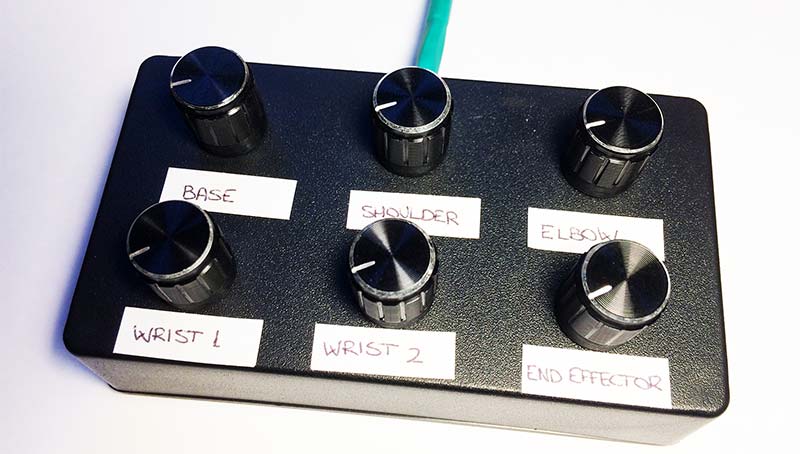
Figure 1. Control box.
Every robot arm joint and the end effector “fingers” are controlled directly with the corresponding rotating knob (potentiometer).
Mode 2: Manually control it with the sliders of a GUI (Graphical User Interface) from the PC (Figure 2)
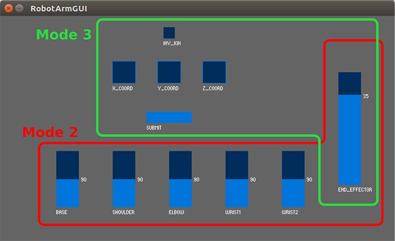
Figure 2. GUI (Graphical User Interface).
In a similar way to the control box, the robot arm joints and the end effector fingers are controlled with the six sliders.
Mode 3: Automatically provide the end effector space coordinates (X, Y, Z) with the GUI from the PC (Figure 2). Here is where inverse kinematics come into play! Plus, the end effector fingers are opened or closed with the END_EFFECTOR slider.
Once the robot arm controller is turned on, during the first four seconds it tries to find a device connected through the serial port. If there is no device connected, Mode 1 will start. If there is a device connected, Mode 2 will start. Once in Mode 2, the user can switch to Mode 3 by clicking on the INV_KIN toggle button in the GUI.
Maybe you noticed that in Mode 3, I mentioned just “space coordinates” and not “pose” (space coordinates + orientation). This is because the end effector orientation will always be horizontal, which is a restriction that was introduced to make calculations easier.
Inverse Kinematics — Geometric Solution
The main problem we will face while controlling robot arms will be to bring the end effector to some specific pose, which means that we will have to work with inverse kinematics. In other words, a set of joint angles will be calculated from a given end effector pose. As explained in the first article last month, different methods can be used for this: algebraic, numerical, and geometric solutions.
For computing the inverse kinematics of my robot arm, I chose the geometric solution, defining a simplified model. We’ll need to refresh some almost forgotten trigonometry that we learned at school! First, we need to measure the length of every robot arm link (Figure 3).
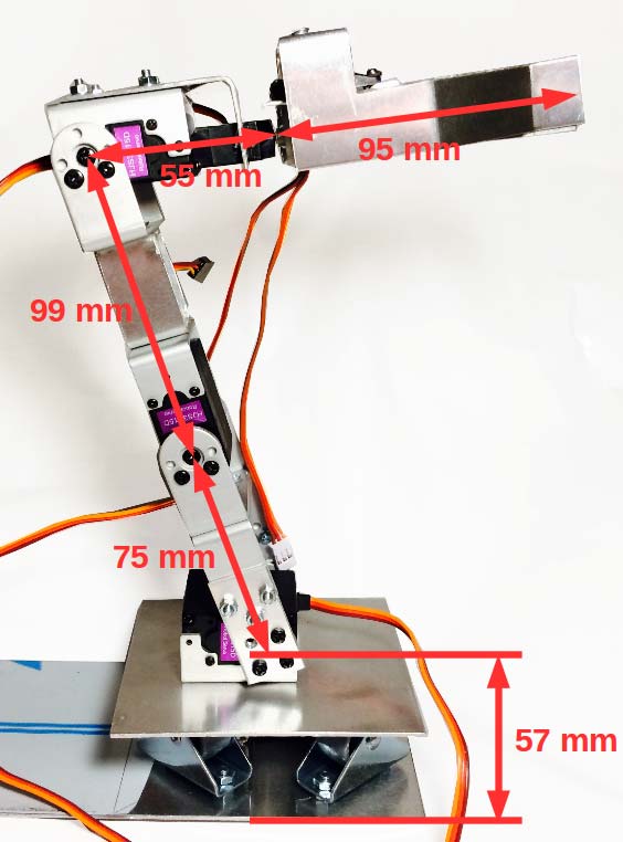
Figure 3. Robot arm link dimensions.
Second, it’s important to define the zero position of every servo, as well as its positive and negative directions of rotation (shown in red in Figures 4 and 5).
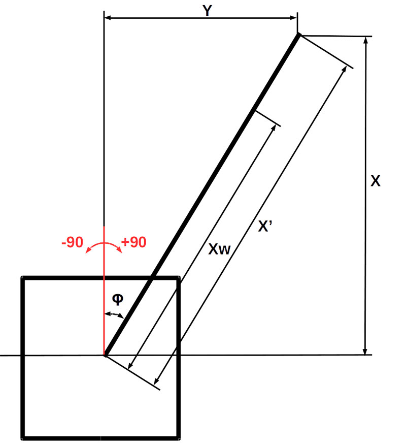
Figure 4. Lateral inverse kinematics (top view).
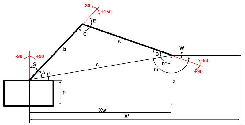
Figure 5. Longitudinal inverse kinematics (side view).
The geometric model is split into two parts: longitudinal and lateral. In the longitudinal part (Figure 5), the space coordinates X and Z are taken as input; for the lateral part (Figure 4), the coordinates X and Y are considered. All the space coordinates will be given in millimeters (mm).
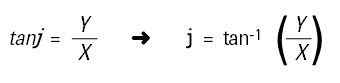
The lateral part of the geometric model is calculated first. If the space coordinate Y is not equal to zero, the robot arm base will rotate with an angle j (see Figure 4). The outcome of the lateral part of the geometric model is Xw — the horizontal distance between the robot arm base and the wrist. To calculate Xw, we need to obtain the angle j first with some easy trigonometry:
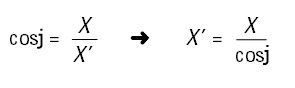
With some easier trigonometry, we obtain the distance X’:
Subtracting the length of the end effector (95 mm, see Figure 3), we get the distance Xw:
Xw = X’ – 95 mm
We’re done with the lateral part! Now it’s time for the longitudinal part of the geometric model.
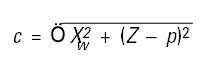
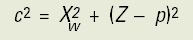
As you can see in Figure 5, a right triangle is created within the lengths c and Xw, and the vertical distance between the base plane and the wrist (Z – p). Applying the Pythagorean Theorem to that triangle, the distance c can be easily obtained:
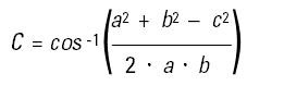
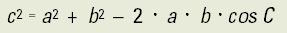
A second triangle is created within two robot arm links (a and b) and the imaginary line c. The lengths a and b are known, and now c is also known, so with the Law of Cosines we can obtain the angle C:
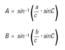
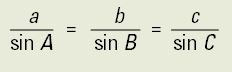
Last but not least, the Law of Sines helps us get the angles A and B:
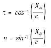
Considering again the right triangle formed between Xw, c, and Z - p, getting t and n is child’s play:
As mentioned before, in our simplified geometric model, the end effector will always remain in the horizontal position, with an angle m with respect to the a link:
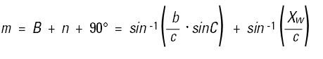
From a more practical point of view, you may wonder which angles out of all this mess will be sent to the servos as inputs ... we have you covered! The servos will rotate from their zero positions (again, marked in red in Figures 4 and 5) with the input angles S (shoulder), E (elbow), and W (wrist):
S = 90° – A – t
E = 180° – C
W = m – 180°
In this simplified geometric model, the longitudinal axis of the wrist joint (defined as Wrist2, as you’ll see later) is not used, as the end effector will always stay parallel to the horizontal plane. We therefore have a spare DOF (degree of freedom) that won’t be used.
That’s it for math class! Let’s start with some programming.
The Arduino Servo Library
The Arduino script that I wrote for controlling the robot arm has been getting more and more complicated as I have been adding new functionalities (servo control, serial communication, initialization function, etc.). Consequently, in this article I will go through some extracts and samples of the script. The whole script with comments/explanations is available at the article link.
A very easy way of controlling servos with an Arduino is using the Servo library. It supports up to 12 servos on the ATmega328 chip (the one we are using, and the one the popular Arduino Uno uses), and up to 48 on the Arduino Mega.
The following sample code shows the four steps needed to control a servo with this library. Moving the servo to our desired angle is as simple as inputting a value in Step 4:
#include <Servo.h> // 1) Include Servo library
Servo servo1; // 2) Define servo object
void setup()
{
servo1.attach(9); // 3) Attach servo on digital
// pin 9
}
void loop()
{
servo1.write(45); // 4) Move servo to desired
// angle
}
Arduino millis() Function
The first problem I faced when I started programming and testing the servos with the Arduino was the servo speed. The servo travelled from its current position to the angle given from my input with such a high speed that it would destabilize the whole arm structure and possibly break it in the long term.
My first solution was to use the delay() function and apply incremental or decremental angle inputs with for loops, so that the servos would move slower. It worked, until I tried to move more than one servo at the same time. Only once the first servo had reached its final position, could the second servo start to move!
I immediately went to the Arduino forums and found out that delay() is a kind of forbidden function, as it totally blocks all the processing capacity of the chip, not allowing other tasks to be performed in the meantime.
I could breathe again when I came across the millis() function: a powerful and popular function of the Arduino library that makes multitasking simple; millis() runs constantly in the Arduino main loop and keeps asking “How much time has passed?” instead of just stopping and waiting (like the lazy delay() function). Here is an example of the code I used in my project, for the case when the final angle (pos2) is higher to or equal as the initial angle (pos1):
if ((pos2 >= pos1)){
if((millis() - lastUpdate) > updateInterval)
{
lastUpdate = millis();
pos += increment;
servo.write(pos2);
}
}
Depending on the defined value for the increment variable, the servo will move faster or slower. So now, not only can my robot arm control several servos at the same time in a slow and smooth fashion, but it can also perform other tasks!
These include reading inputs (USB, Bluetooth, potentiometers, etc.) and processing new servo positions, among others.
Control Box
As discussed in the first article, the control box has 6x 10K potentiometers, which are connected through a Micro JST 2.0 PH eight-pin connector to the analog inputs of the Arduino chip (pins 23 to 28). Each potentiometer controls a specific servo (except for the end effector, where two servos are controlled simultaneously by a single potentiometer).
The following code shows how the input given by a potentiometer (pos) is mapped down to a desired range (posm); in this case, from 0 to 180 degrees:
pos = analogRead(pot1); // Read analog input from potentiometer pot1
posm = map(pos, 10, 1023, 0, 180);
// Map down the potentiometer input from its
// original range (0 to 1024) to 0 to 180 degrees
The mapped down value of the potentiometer is then used as input of the servo angle.
Serial Communication
The robot arm will communicate with other devices (PC, smartphone, etc.) through the serial port (USB or Bluetooth). Although at first my plan was to compute the inverse kinematics with the Arduino, in the end I have decided to compute it externally (i.e., with the PC) in order to simplify the Arduino code and avoid pushing the ATmega328 chip to the limit.
Therefore, the input to the robot arm controller (in both Modes 2 and 3) is an 18-character string with the six servo angles (Base, Shoulder, Elbow, Wrist1, Wrist2, and End_effector).
An example of this string is shown in Figure 6.

Figure 6. Robot arm controller 18-character input string.
Given that there are no spacers to separate one value from another, all the angles must always be given with three digits (0 degrees will be 000, 12 degrees will be 012, and so on).
Although a bit tricky in the beginning, getting an Arduino connected with other devices over the serial port is a piece of cake! So, don’t panic if you spend a couple of hours racking your brains. I also went through that!
The number one rule is to use the same baud rate in all the devices connected through the serial port (most commonly 9600 bps).
The following chunk of code shows how the serial communication is implemented in the Arduino to obtain the Base angle (servo1) from the input string.
Note that the elements used to include the servo library and define the servo1 object have been omitted for the sake of simplicity (for the whole code, see the Arduino script available at the article link):
void setup() {
Serial.begin(9600); // Open serial port and set data
// rate to 9600 bps
}
void loop() {
while (Serial.available()>0) {
// Proceed only when there is data received
delay(10); // Let’s give Arduino some time to take
// a breath
char c = Serial.read(); // Get one byte from
// the serial buffer
readString += c; // Read characters from serial
// buffer into a string
}
if (readString.length() >0) {
// Proceed if the string has any character
servo1 = readString.substring(0, 3);
// Get first three characters of string
}
// Now that we have the servo1 angle in string format,
// we need to convert it into an integer number:
char carray1[18]; // Create 18-digit array to
// store values of all servos
// Convert servo1 angle string into an integer number
// (pos1):
servo1.toCharArray(carray1, sizeof(carray1));
pos1 = atoi(carray1);
sweeper1.Update(); // Update sweeper function for
// servo1 (see whole script)
readString=”“; // Clear string variable for new
// input
}
We can now control the robot arm through the serial port (hooray!). We just need a couple of finishing touches and we are done!
Initialization Script
As explained previously, the robot arm controller waits for four seconds after being turned on and checks for devices connected over the serial port. If no serial device is connected, Mode 1 (control box) will start; if there’s a serial device, Mode 2 (manual control with GUI) will start.
This is done with an initialization script on both sides of the serial port: The robot arm electronic controller “listens” for any serial device, and the device connected through the serial port must send any data message to the robot arm controller (it’s important for this to be within the first four seconds!).
This is implemented in the Arduino code as follows:
int goto; // Declare variable goto as integer
// number
void setup() {
Serial.begin(9600); // Open serial port and set data
// rate to 9600 bps
while(Serial.available()==0 && millis()<4000);
// Wait for up to 4 sec. if no data is received
if(Serial.available()>0){
// Proceed if there’s data received:
goto = 1; // Set goto variable to 1
}
}
void loop() {
if(goto == 1){ // If goto was set to 1:
// THE CODE SHOWN IN THE “SERIAL COMMUNICATION” SECTION
// IS IMPLEMENTED HERE
}
else{ // If goto was not set to 1:
// THE CODE SHOWN IN THE “CONTROL BOX” SECTION IS
// IMPLEMENTED HERE
}
}
The initialization script on the other side of the serial port (PC) will be shown shortly.
Graphical User Interface
For years, I had heard wonders about Processing, so I decided to give it a try for creating a GUI. I couldn’t be more pleased! It took me just a couple of hours to start defining the layout of the GUI with Processing. Before that, I played around with some examples and did some research through online tutorials. The online community is not as huge as it is for the Arduino, but the similarity between both programming languages makes it very easy to get started with Processing.
For the GUI, I needed six sliders to move the robot arm servos; a toggle button to switch between Modes 2 and 3; three text boxes to input the end effector coordinates (X, Y, and Z); and a button to submit these values.
I came across the ControlP5 library (see Resources), which provided all of that with a simple and straightforward implementation. The final GUI layout is shown in Figure 7.
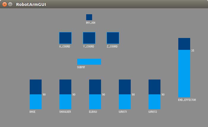
Figure 7. Processing GUI.
The Processing script performs four different functions:
• Creation of GUI
• Initialization script
• Computation of inverse kinematics
• Transmission over the serial port of 18-character
strings with the six servo angles
The code that follows shows how the control elements of the GUI are implemented, and how the string with the servo angle Base is transmitted over the serial port. For simplicity, only one element of each type is shown (slider, text box, toggle button, Submit button), as well as only one servo angle (instead of the whole 18-character string with all the servo angles). Again, for the whole code, see the Processing script.
import processing.serial.*; // Import serial library
import controlP5.*; // Import controlP5 library
ControlP5 cp5; // Call controlP5 object
Serial myPort; // Create object from Serial
// class
int Base; // Declare Base integer
boolean Inv_Kin = false; // Declare boolean for
// toggle button
String X_coord; // Declare X_coord string
void setup() {
myPort = new Serial(this, portName, 9600);
// Declare serial port
myPort.write(1);
// INITIALIZATION FUNCTION: Write something to
// serial port
size(700,400); // Define size (in px) of GUI
// background
noStroke();
cp5 = new ControlP5(this);
// Needed for creating controlP5 objects
PFont font = createFont(“arial”,20);
// Define font type and size
cp5.addToggle(“Inv_Kin”,false,290,20,20,20);
// Define toggle button, inactive by default
cp5.addSlider(“Base”) // Define slider for
// Base
.setPosition(100,240)
.setSize(40,100)
.setRange(0,180)
;
cp5.addTextfield(“X_coord”) // Define text box for
// the X coordinate
.setPosition(200, 80)
.setSize(40, 40)
.setFont(font)
.setAutoClear(false)
;
cp5.addBang(“Submit”) // Define Submit button
.setPosition(260, 170)
.setSize(80, 20)
.setTriggerEvent(Bang.RELEASE)
;
}
void draw() {
background(100,100,100); // Define color of GUI
// background
if(Inv_Kin==false){ // Proceed if the INV_KIN toggle
// button is inactive
String Base_s = nf(Base, 3);
// Convert numerical Base value into string with 3 // digits
myPort.write(Base_s);
// Write Base_s (string) value to serial port
}
}
void Submit() { // The Submit() function will be called
// whenever the Submit button is
// pressed.
X_coord = cp5.get(Textfield.class,”X_coord”).getText();
// Get value (string) of X coordinate
int X = int(X_coord);
// Convert value of X coordinate into integer (to be
// able to make calculations with it)
// INVERSE KINEMATICS ARE CALCULATED HERE (SEE WHOLE
// SCRIPT)
myPort.write(Base); // Write Base (integer) value to
// serial port
}
It looks quite similar to Arduino code, doesn’t it? In the setup() function, the different graphic elements (background, sliders, text boxes, toggle button, Submit button) are created.
The draw() function is comparable to the loop() function for the Arduino, as it loops consecutively which allows the program to change and respond to the user inputs.
Note that despite having defined the sliders in the setup() loop, every time the user moves them, they provide a new value!
However, the slider (float) values are later converted into strings in the draw() function (only in Mode 2, when the INV_KIN toggle button is inactive).
The initialization script “on the other side” of the serial port consists of just a data byte that is sent through the serial port, and is implemented within the draw() function of the Processing code:
myPort.write(1); // Write 1 to serial port
The inverse kinematics are computed in the Submit() function, when the Submit button is pressed by the user (taking as inputs the space coordinates X, Y, and Z from the text boxes). As this is just the implementation of the trigonometric functions shown in the previous “Inverse Kinematics — Geometric Solution” section, you can have a look at the Processing script.
Bluetooth Connectivity
As you may recall from the first article, the robot arm controller has an HC-06 Bluetooth board, which I decided to include in my design for experimenting with wireless connectivity. The implementation of serial communication through Bluetooth with the Arduino is pretty similar to the regular serial communication via USB.
Since the HC-06 board is connected to the digital pins 10 and 11 of the Arduino chip (normally, it would be connected to the RX/TX pins, but these were already taken by the FTDI232 USB to serial breakout board), we need to use the SoftwareSerial library:
#include <SoftwareSerial.h>
SoftwareSerial BT(10, 11);
The serial communication is initialized in the setup() function with the following command:
BT.begin(9600);
In the rest of the script, the old Serial shall be replaced by BT; for example:
char c = BT.read();
I have also included a second Arduino script with serial communication through Bluetooth in the download package. A future improvement that I have in mind is to merge both scripts (USB/Bluetooth) into a single one, so the user can choose to control the robot arm either through USB or Bluetooth, with some sort of initialization function.
I have created another GUI for my Android smartphone with MIT App Inventor — an amazing online tool for developing Android apps. Everything is done in a visual environment, which means that you don’t need to write a single line of code. Just drag and drop blocks!
For now, the GUI is quite simple (Figure 8) and only includes the six sliders to control every robot arm joint.
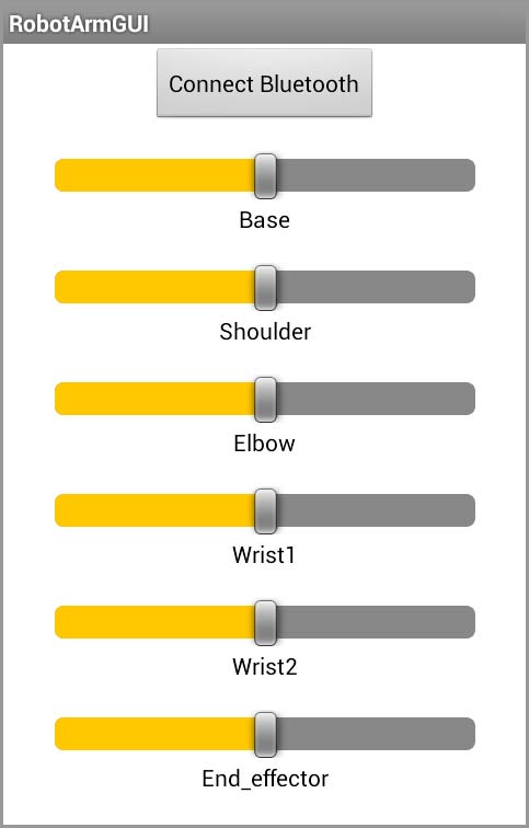
Figure 8. Android GUI designed with MIT App Inventor.
Load Arduino Scripts to the ATmega328
For loading Arduino scripts to the ATmega328 chip, I use an ISP (In-System Programmer) shield that I built a long time ago (Figure 9) when I started to create my own printed circuit board designs for projects.
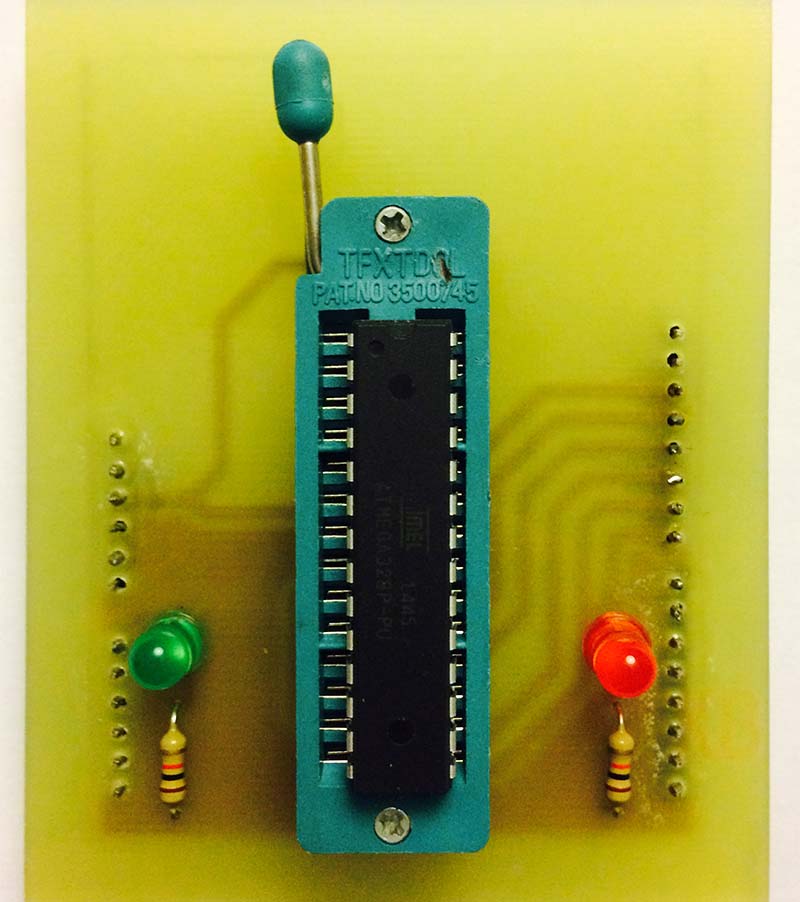
Figure 9. Homemade Arduino ISP shield.
It’s very simple to build one of these, and they’re also quite cheap if you want to buy one. I recommend you get one!
Final Thoughts and Considerations
All in all, my project so far has required the practical application of a wide variety of engineering/scientific fields: mechanics, electronics, chemistry, programming, mathematics, and — why not — project planning. Hey, this is robotics!
In general, the whole project has been a sort of obstacle course with a lot of issues to overcome. The programming part has been especially challenging, and I had to spend a lot (a lot!) of hours developing the Arduino and Processing scripts. It’s very important to start testing simple code with individual elements, and then continue putting it all together like a jigsaw puzzle.
For example, in this particular project, we use seven servos. So, it’s best to first make one or two servos work properly, and then apply that code to the whole set of servos. Also start writing the code and testing specific functionalities (e.g., servo control, serial communication). Once they work fine separately, put them together.
Next Steps
As I mentioned before, the possibilities of adding functionalities to the robot arm are almost infinite thanks to serial communication. The only limit is your imagination! I still have plenty of ideas to implement in the future, such as robot vision with the addition of a webcam mounted on the end effector.
This is just the beginning of a long adventure! SV
Trigonometric Functions
Pythagorean Theorem (only applicable to right triangles): The square of the hypotenuse (c) is equal to the sum of the squares of the other two sides (Xw, Z-p):
Law of Cosines: Side c can be calculated if the angle opposite (C) and the two other sides (a, b) are known:
Law of Sines: Relates the side lengths of a triangle to the sines of its angles:
Resources
Arduino official website:
www.arduino.cc
Processing official website:
www.processing.org
controlP5 website:
www.sojamo.de/libraries/controlP5
MIT App Inventor:
appinventor.mit.edu
My blog:
funwithcables.wordpress.com
Article Comments