An ARDUINO Controlled Robot Arm
By Ricardo Caja Calleja View In Digital Edition
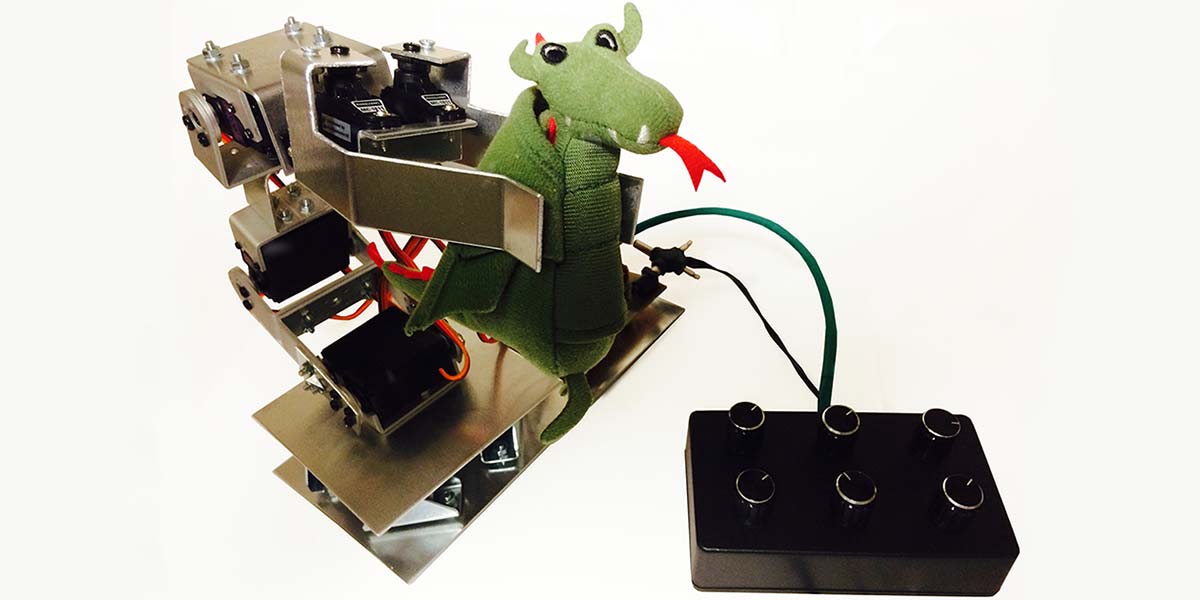
A while back, I completed a MOOC (massive open online course) about robotics, which got me immersed in the amazing world of robot arms. Being involved for some time with tinkering and electronics, I decided I was going to build my own robot arm and try to implement everything I had learned in that course in the “real world.”
I decided to create an Arduino controlled robot arm that I could use as a platform to test all the theory that had been covered, and experiment with new ideas. I also wanted to be able to interface to the arm in as many ways as I could imagine with other devices (such as my laptop, smartphone, etc.). This would allow for future development, like adding robotic vision by means of a webcam.
Let’s start first with some theory and basic concepts about robot arms.
What does “Degree of Freedom” (DOF) Mean Exactly?
Surely, one of the first questions for those new to robotics or mechanics is: What does “Degree of Freedom” mean? The DOF of a mechanical system is a specific mode in which said system can move; that is, a rotational or a translational movement.
In the case of robot arms, rotational and translational movements are produced by revolute and prismatic joints, respectively. Most types of robot arms have only revolute joints, materialized with servos. To find out how many degrees of freedom a robot arm has, it is enough to just count the amount of servos since each servo provides one DOF (of rotational movement). So: Number of servos = Number of DOF. Easy!
Parts of a Six DOF Robot Arm
Why exactly six DOF? Because six DOF is the minimum that an arm needs to be able to reach to any point within a specific volume of space from every possible angle with its end effector (claw, manipulator, hand, etc.). Many industrial and hobbyist robot arms have six DOF.
A robot arm can be compared with a human arm, which has at least six DOF. As observed in Figure 1, the robot arm also has a shoulder, elbow, wrist, and “hand” (end effector). Note that the shoulder and the wrist of the robot arm have two DOF each, as there are two perpendicular servos whose axes intersect in the joint.
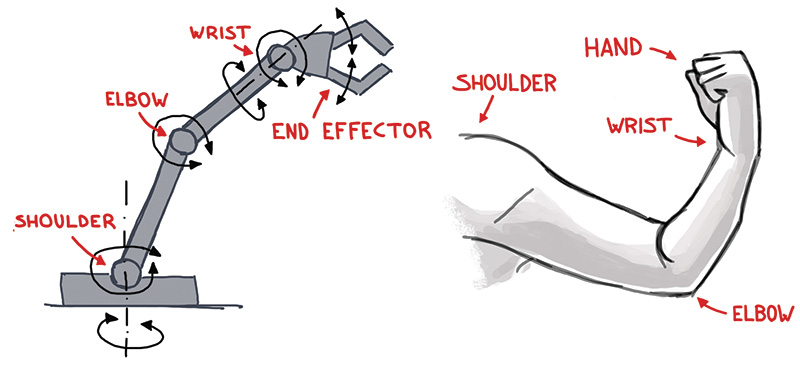
FIGURE 1. Comparison of robot arm and human arm.
An arm with less than six DOF is classified as an “under-actuated” arm, whereas an arm with more than six DOF is a “redundant arm.”
How to Calculate Motion: Forward and Inverse Kinematics
Let’s see how a robot arm can be controlled. There are two approaches to this:
- Forward kinematics: The end effector space coordinates and orientation (from now on “pose”) are calculated considering a given set of joint angles.
- Inverse kinematics: The joint angles are calculated considering a given end effector pose.
It is clear that in most cases, we will need to bring the end effector to a specific pose and therefore calculate the necessary joint angles, which means that we will have to deal with inverse kinematics! Inverse kinematics is rather complicated compared with forward kinematics, and there are different approaches to solve this problem:
- Algebraic solution: Very complicated equations in matrix form are needed.
- Numerical solution: Provides an initial guess of the joint angles and performs iterations to minimize the error.
- Geometric solution: Uses trigonometry based on the robot arm geometry.
Although the geometric solution may get very complicated for complex arms, a simplified model was my choice, as it was the easiest method to implement in the Arduino code. (More details on this will follow in the second article.)
How My Robot Arm Works
The possibilities of controlling the robot arm from a PC/Raspberry Pi through the serial port (USB) are almost infinite: Matlab or Python script, Processing, Robot Operating System (ROS), Arduino IDE (integrated development environment; serial monitor), etc. The controller also interfaces with an Android/iOS device (tablet, smartphone) through Bluetooth, and can be controlled manually using a “control box” with rotating knobs as well.
An important upgrade that I plan for the future (as previously mentioned) is the addition of robotic vision with a webcam mounted on the end effector and connected to a PC/Raspberry Pi. This way, the robot could recognize different types of objects (by color and/or size) and grab them.
Construction of the Robot Arm
The robot arm is divided into three main elements:
- Robot arm body
- Hardware (electronic controller)
- Software
In the following sections, I will go through each of these parts.
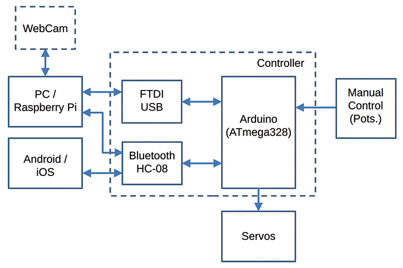
FIGURE 2. Hardware block diagram.
Construction of the Robot Arm Body
To build the robot arm body (see Figure 3), I purchased some servos on eBay that already included aluminium brackets so that it would be easier to connect the servos to each other, as well as to other elements of the robot arm (see Figure 4 for the aluminium brackets I made).
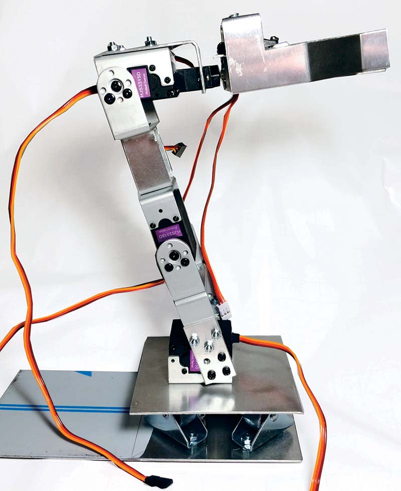
FIGURE 3. Robot arm body.
These servos rotate up to 180 degrees and their maximum torque is 15 kg, which is more than enough.
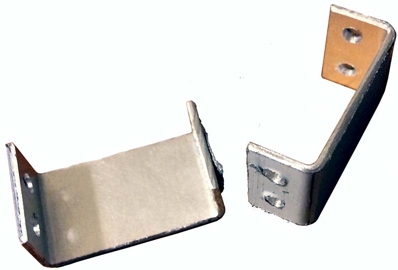
FIGURE 4. Aluminium brackets.
The two main challenges that I faced while building the arm body were the design of the base and the end effector.
In order for the base to be able to rotate around the vertical axis and be stable enough to stand the whole weight of the arm, I used four small wheels that I found in a DIY store (yes, the kind used for wardrobe doors!). Below the horizontal plate, there’s a micro servo fixed with brackets to the main base (Figures 5 and 6).
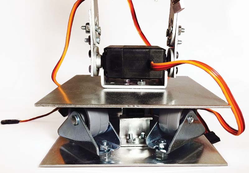
FIGURE 5. Robot arm base.
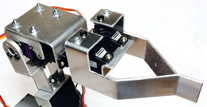
FIGURE 6. Robot arm end effector.
This servo is not very strong, but for now it has done the job and its height is minimal, so the rotating base is kept as low as possible (for the overall center of gravity to be kept in a low position). For the base and end effector, I used servos that can also rotate up to 180 degrees. Otherwise, the robot arm movements would be very limited.
The end effector is rotated by another micro servo. As I couldn’t find a simple way of adding a gear mechanism to control the two “fingers” of the end effector with a single servo, I decided to use two micro servos for controlling the two fingers.
Design and Assembly of the Electronic Controller
The controller consists of a homemade printed circuit board (PCB) and a control box that is connected to the PCB through a JST 2.0 PH eight-pin connector. The controller “brain” is a stand-alone Arduino chip (ATmega328) that processes all the analog inputs (from PC/Raspberry Pi/Android/iOS/control box) and provides the seven servos with the appropriate output signals (Figure 7).
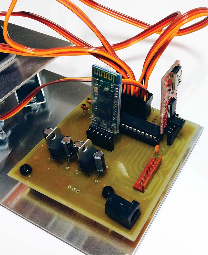
FIGURE 7. Controller PCB.
The power supply is provided in two independent channels of 5V and 6V for the Arduino chip (and other control elements of the PCB) and the servos, respectively.
This is a very important fact to consider when we include servos or motors in our projects, as they usually present a very high current consumption. If they were directly powered by the same channel as the Arduino (ATmega328) chip, it could basically burn out when the servos get hungry!
The control box has six rotating knobs which are used to manually control every joint of the robot arm (base, shoulder, elbow, two wrist axes, and end effector); refer to Figure 8.
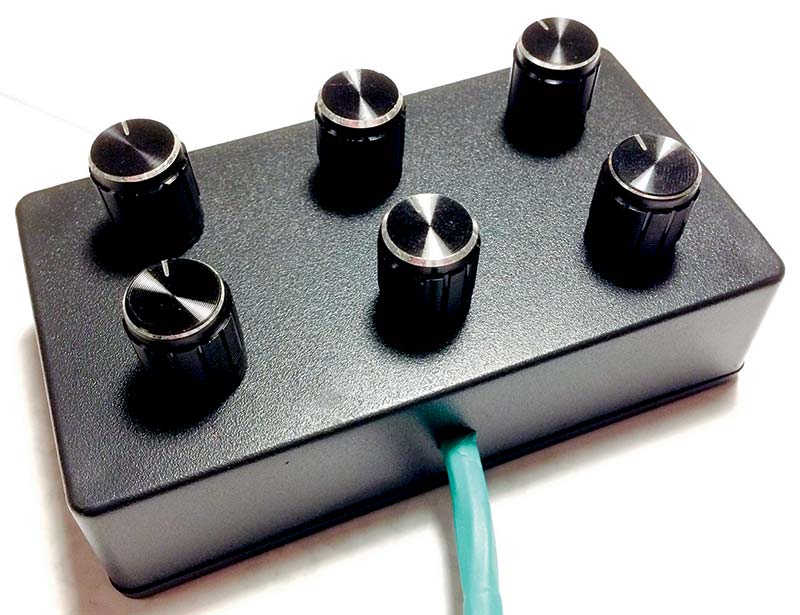
FIGURE 8. Robot arm control box.
The potentiometers attached to the rotating knobs produce a voltage range that is used as analog input by the Arduino chip. Depending on this input, the Arduino will command the appropriate output signals to the digital pins where the servos are connected.
The Controller Board
You can see the list of electronic components needed to build the controller board in Parts List.
Controller Board Parts List
- DC barrel jack adapter
- SPDT slide switch
- 4x 10 µF capacitors
- 5V Voltage regulator (LM7805)
- 6V Voltage regulator (LM7806)
- Micro JST 2.0 PH eight-pin male connector plug
- 2x Female pin header (1x6)
- 3x Male pin header (1x6)
- 28-pin DIL IC socket
- Atmel ATmega328 chip (DIP28). If it does not have the Arduino bootloader installed, you will need to install it.
- 16 MHz Crystal
- 2x 22 pF Capacitor
- 0.1 µF Capacitor
To design the PCB layout, I used my old beloved friend, KiCad. (KiCad is an open source EDA software for Windows, OSX, and Linux.) I started to use it almost 10 years ago in my first graduate job, and after trying other PCB software, I have always come back to KiCad. Although sometimes a bit tricky to use, it’s open source, the online community for solving issues is pretty big, and it’s always under continuous improvement. Plus, plenty of libraries from Eagle (such as those from SparkFun) are regularly converted into KiCad format.
The first step to define the PCB layout is to draw the schematics in Eeschema — KiCad’s schematic editor (Figure 9).
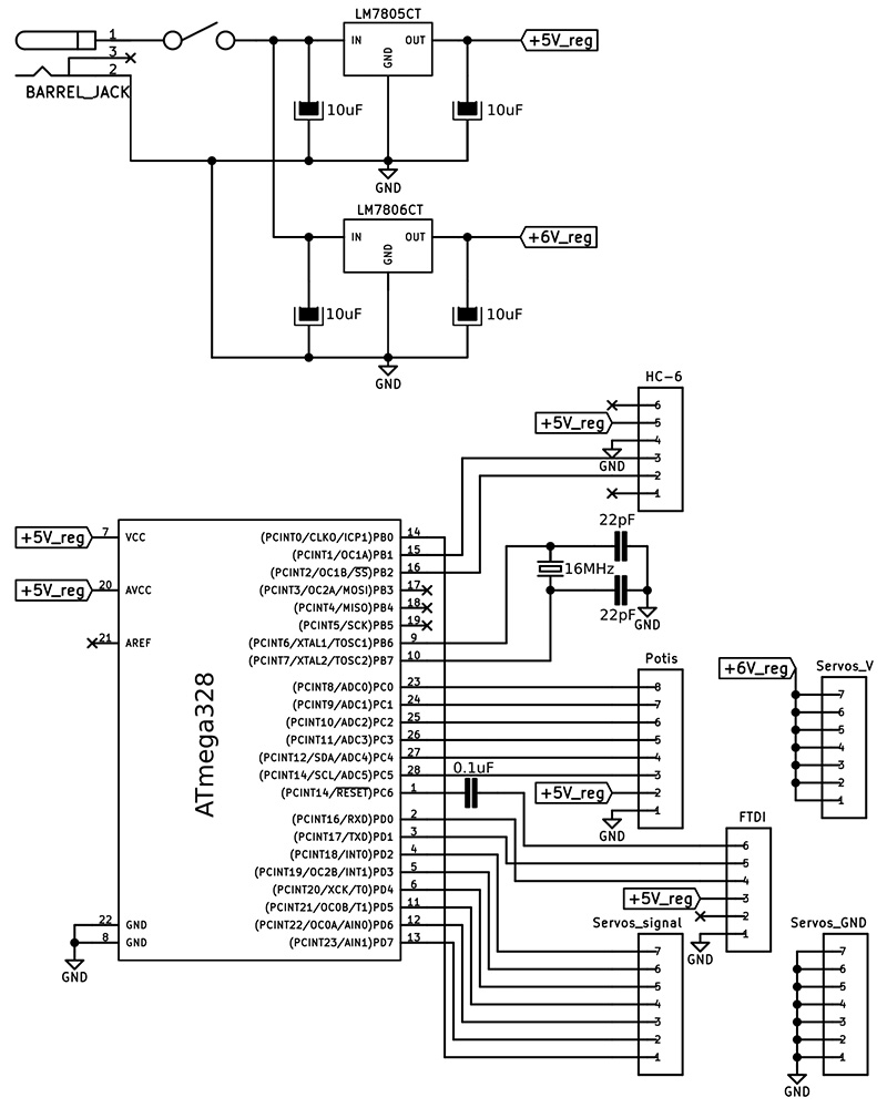
FIGURE 9. Controller board schematics in KiCad.
Then, a “netlist” has to be generated, which is a file that will be required by PcbNew (KiCad’s PCB editor module) to import the needed PCB components properly connected. For newbies, all this may produce more than one headache, but don’t panic! Once you’ve got a bit of practice, it becomes a rather smooth task.
The upper part of Figure 9 shows the voltage regulators, which convert the input voltage (up to 12V according to the datasheet) into two voltage levels in two independent channels: 5V for the Arduino chip (and other control elements), and 6V for the servos. The lower part shows the Arduino chip with the interfaces (pin header connectors) to the following elements:
- Control box (“Potis”): Micro JST 2.0 PH eight-pin male connector plug
- Servos GND channel (“Servos_GND”): Male pin header (1x6)
- Servos 6V channel (“Servos_V”): Male pin header (1x6)
- Servos signal channel (“Servos_signal”): Male pin header (1x6)
- FTDI232 USB to serial breakout board (“FTDI”): Female pin header (1x6)
- HC-06 Bluetooth board (“HC-6”): Female pin header (1x6)
The Printed Circuit Board
Once the whole bunch of components is imported into PcbNew, it’s important to make sure that the correct footprints are used. These next steps are my favorite: Define the board boundaries; place the components in the correct positions; and manually route the tracks. Since I didn’t intend to use double-sided PCBs, I had no other way but splitting the ground (GND) area into different “islands.” I later joined all the GND islands together, soldering cables and making a single GND region. In Figure 10, you can see the final PCB layout in KiCad.
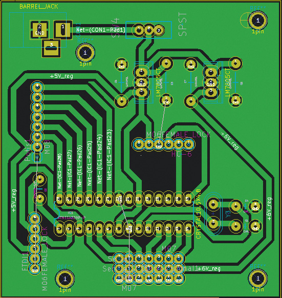
FIGURE 10. Controller PCB layout in KiCad.
Once the PCB layout is ready in KiCad, there are several methods to make the physical board.
In fact, this could make for a whole article! My preferred method is the use of a photosensitive board with UV light exposure; NaOH (caustic soda) + H2O (water) as the developer solution; and H2O2 (hydrogen peroxide) + HCl (hydrochloric acid) as the etching solution.
I managed to get a pretty good result this time (Figure 11). After drilling the holes with a Dremel using a 3/64” drill bit, it was time to solder all the components.
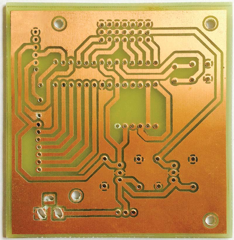
FIGURE 11. Final PCB.
Figure 12 shows the PCB with all the components soldered.
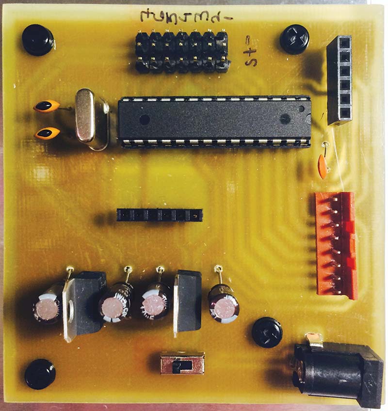
FIGURE 12. Final PCB with components soldered.
Assembly of the Control Box
For the electronic components needed to build the control box, see the Parts List for it.
Control Box Parts List
- ABS enclosure 113 x 63 x 28 mm (a similar size is also suitable)
- Micro JST 2.0 PH eight-pin female connector plug with wires
- 6x 10K potentiometer
- 6x 6 mm shaft potentiometer control knob
The schematic of the control box is shown in Figure 13. It simply takes the GND and 5V signals from the controller board through the Micro JST 2.0 PH eight-pin connector (pins 1 and 2, respectively), and provides the output voltage from the potentiometers (pins 3 to 8).
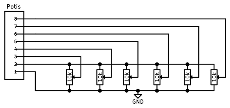
FIGURE 13. Control box schematic.
For the control box, I simply used a small stripboard to solder all the connections of the potentiometers on to it (Figure 14).
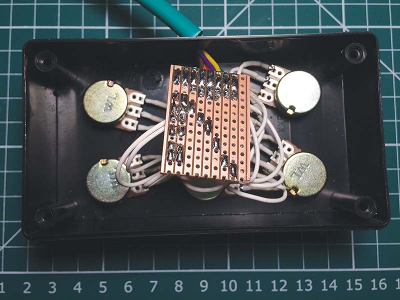
FIGURE 14. Control box connections.
FTDI232 USB to Serial Breakout — HC-06 Modules
The robot arm controller interfaces with the PC/Raspberry Pi through the serial port (USB) by means of an FTDI232 USB to serial breakout board, as well as through Bluetooth with an HC-06 board (see Figure 15). These modules are connected to the six-pin female headers of the controller.
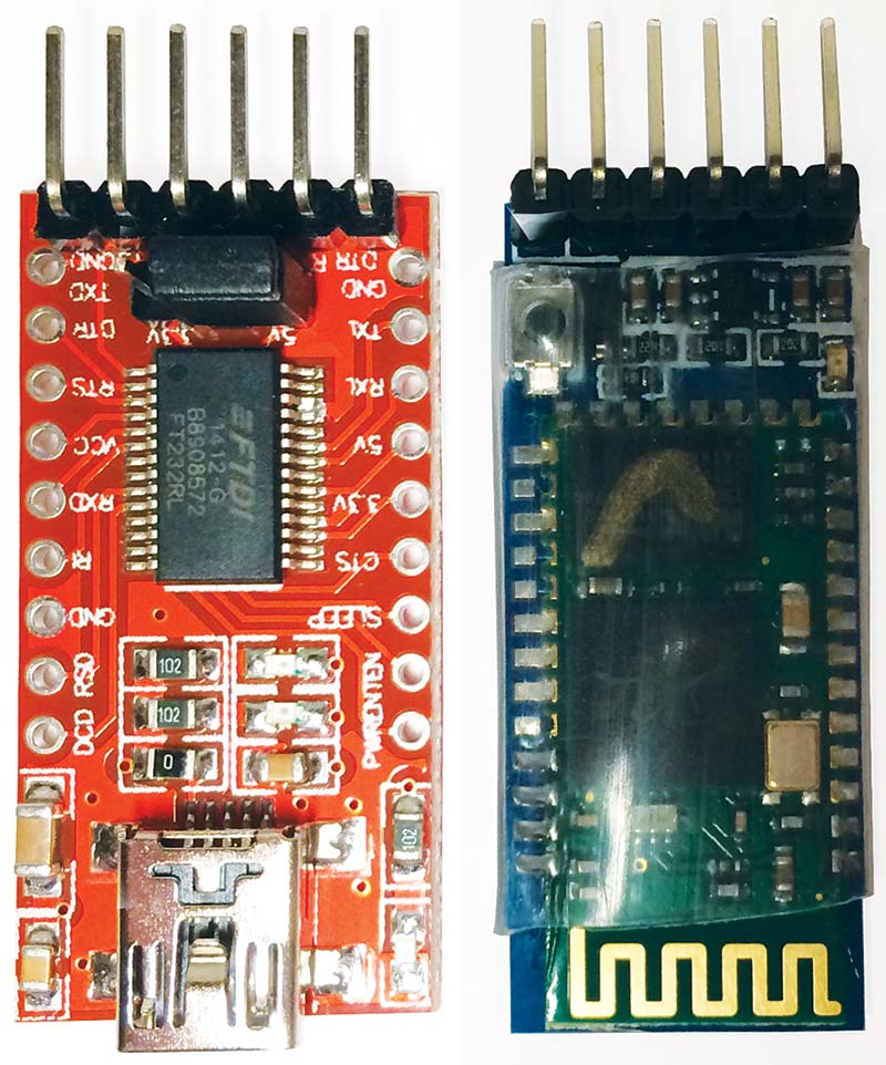
FIGURE 15. HC-06 and FTDI232 USB to serial breakout board.
At first, I wondered if it would be possible to have serial communication on more than two pins (RX, TX) of the Arduino chip. With the function SoftwareSerial library, it was easy peasy! Declaring the digital pins where the FTDI chip or the Bluetooth module is connected creates a virtual serial port/UART. So, now the FTDI232 USB to serial breakout board is connected to pins RX/TX, and the HC-06 board to digital pins 10 and 11.
I’ll have more details on this in the next article, where I will dive into the software.
Final Thoughts and Considerations
After being involved for some time with robotics, I’ve learned some important lessons. First off, since we’re working with servos and elements that move, one has to be extremely careful with their range of movement, making sure that there’s always enough clearance around them to allow their free movement. Otherwise servos, cables, and structural parts of the robot or even objects around it may get damaged. Or, you can even get your fingers injured!
Also make sure that you define the appropriate initial servo positions in your code. It happened to me when all the initial servo positions were set to zero degrees. After powering up the controller, the arm made abrupt movements hitting everything around it!
Second, try not to manually rotate servos when they’re not powered, as it may cause damage in the gears — especially if they’re made of plastic. Furthermore, if your budget allows it, go for servos with metal gears.
Last but not least, be careful with the polarity of servo connections! Connecting a servo with the wrong polarity will surely damage the servo electronics.
Next Steps
In the next article, we will actually see my robot arm moving! I will show how I defined the geometrical solution for controlling the robot, as well as how it was implemented in the Arduino code.
I will also show how to interface the robot arm with a PC/Raspberry Pi through the serial port (USB), as well as with an Android/iOS device by means of Bluetooth. Stay tuned! SV
Resources
My blog
funwithcables.wordpress.com
Arduino official website
www.arduino.cc
KiCad official website
https://www.kicad.org/
Article Comments