The Schmitt Trigger and How It Works
By Roger Secura View In Digital Edition
The Schmitt trigger is one of the most widely used circuits in the electronics industry. If you have to clean up a noisy signal, catch a slow rising voltage at specific points, or need to eliminate unwanted triggering in your robot line follower circuit, then the Schmitt trigger is the right tool for the job.
Look at Figure 1 and you’ll see a simple Schmitt trigger circuit.
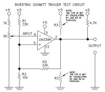
Figure 1.
The nice thing about Schmitt trigger circuits is the fact that you can set up two voltage level trigger points — each of which can be selected simply by adjusting a few resistor values.
In Figure 1, it’s the combination of the resistors R1, R2, and R3 which sets up the upper trip point (UTP) and lower trip point (LTP). Notice also in Figure 1 that the combination of the R1 and R2 resistors forms a simple voltage divider circuit.
Let’s assume the input voltage level on the inverting terminal (pin 4) in Figure 1 is 0V. That means the output voltage (pin 2) is +5 volts. Remember I said that resistors R1 and R2 in Figure 1 form a voltage divider circuit? Well, with the output at +5V, R3 (at pin 2) is “seeing” 5V, and is technically in parallel with R1.
If we use the voltage divider formula, we can calculate the UTP as shown:
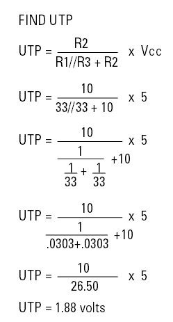
Now that we have the UTP set to 1.88V, the input signal voltage must rise above this point in order for the output voltage of the comparator to swing to the opposite level (zero volts).
Okay, what happens when the input signal goes above 1.88V and output swings low? Well, R3 now sees 0V at pin 2 and it is essentially tied to ground. This, in turn, makes R2 in parallel with R3. Again, we use the voltage divider circuit formula to determine the LTP:
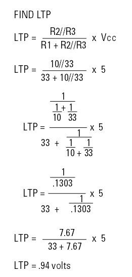
The LTP is set at .94V. Now, any signal voltage applied to the inverting input terminal (pin 4) will have to go below .94V before the output of the comparator will swing in the opposite direction (+5V). Notice — and this is important — how the output voltage level of the comparator (0V or 5V) determines which resistor (R1 or R2) is in parallel with R3. This gives the Schmitt trigger circuit the ability to lock in either the UTP or the LTP simply by having R3 in parallel with R1 or in parallel with R2.
This means that any input signal into the comparator will not affect the output voltage of the comparator until it has risen above the UTP or fallen below the LTP. Figure 2 shows just how this works.
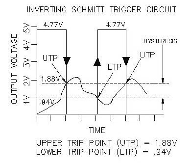
Figure 2.
Again, let’s assume we have 0V at the negative input terminal (pin 4) and +5V at the output terminal (pin 2). Now, we apply a slow rising signal (0V to 5V) into the inverting terminal. Once the voltage rises a little above 1.88V, the output voltage of the comparator will swing negative (0V). This causes R2 and R3 to be in parallel and this, in turn, sets up the LTP.
Now, the comparator’s output will not swing high again until the input signal voltage goes a little below .94V. During this time, the input signal voltage can fluctuate up or down all it wants and it still won’t affect the output of the comparator.
You’ll notice in Figure 2 a “voltage gap” between the 1.88 volts and .94 volts. This narrow channel is commonly referred to as a “hysteresis” gap (i.e., UTP minus LTP). It serves as a “band gap” or dead zone for ignoring any input signals which fall into its constraints. The selection of resistors R1, R2, and R3 determines the hysteresis gap.
I set up a test circuit (refer to Figure 1 again) using an LM339N IC and made a chart of the inputs and outputs of the comparator in order to show you how the UTP and LTP actually work. Figure 3 shows the results of the test.
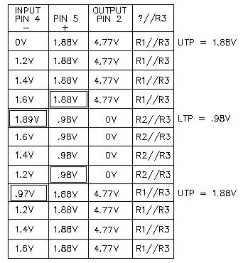
Figure 3.
You’ll notice in Figure 3 that the input signal (pin 4) rises from 0V to 1.2V to 1.4V to 1.6V, and yet the output voltage of the comparator (pin 2) stays high (4.77V). It’s not until the input signal reaches 1.89V that the output (pin 2) swings to 0V. The LTP (.98V) is now activated (i.e., R2//R3) and the output voltage is locked in at 0V.
As you can see, the chart reveals a simple fact about how the Schmitt trigger comparator circuit works.
The input signal voltage has absolutely no effect on the output voltage of the comparator — at least not until the signal reaches one or the other predetermined set points (UTP or LTP).
So, to sum this up, there are two key points to remember about the Schmitt trigger circuit:
- The UTP and LTP of a Schmitt trigger circuit can be determined by using a simple voltage divider network.
- The output voltage level (high or low) of the comparator is what determines which resistor (R1 or R2) is currently in parallel with R3 and that, in turn, determines which one of the two trip points is active at any one time.
I hope this helps to clear up any confusion you might have about the Schmitt trigger comparator circuit.
Real World Application
Okay, now that you’ve got a handle on how the Schmitt trigger works, let’s take a look at a real world application. Figure 4 is a simple circuit you can wire together to control a single axis (east to west) motorized solar panel that tracks the sun as it moves across the sky.
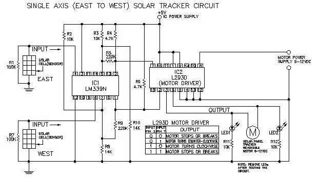
Figure 4.
What the circuit will do is detect the amount of sunlight shining onto two small (14 mm x 35 mm) solar cells. The solar cell (i.e., sensor) receiving the most light will trip one of the two Schmitt trigger comparators (IC1). The UTP and LTPs on each Schmitt trigger requires two different levels of sunlight be present at each sensor before the circuit will respond. Now, when any one of the two comparators trip, it will set up a 5V, 0V or 0V, 5V situation at the two input pins (2, 7) of the motor driver IC (IC2).
These two input pins control which direction (CW or CCW) the solar panel motor will turn (see the chart in Figure 4). Also, any time both sensors receive an equal amount of sunlight or shade, the Schmitt trigger output pins 1 and 2 will present the L293D input pins with a 5V, 5V or 0V, 0V, and immediately shut the motor off.
In other words, we don’t want the solar panel moving when it’s aiming directly at the sun (i.e., correct alignment) or when the sun isn’t shining.
For example, let’s say the solar panel is facing straight up (12 noon) and the sun is just rising in the east (see Figure 5).
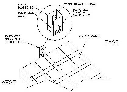
Figure 5.
The east sensor — because it physically faces due east — will receive a little more light than the west sensor. This imbalance will force the motor driver IC to turn the solar panel CCW — towards the east. Eventually, as the west sensor rotates towards the east, it will receive the same amount of sunlight as the east sensor. At that time, the L293D IC will shut the motor off.
That’s nice and all, but what happens to the circuit when the sun is playing peek-a-boo with the clouds? Does the motor just keep oscillating between on and off? No! It’s not how rapidly the sun appears or disappears that affects the circuit; it’s whether or not there’s an imbalance in the amount of sunlight striking the two sensors.
The only time the sun can activate the motor is when the sun changes its position in the sky (i.e., sun light imbalance between sensors). The fact that the sun moves across the sky by one degree of arc every four minutes (15° hr) means it takes at least four minutes before the circuit senses any change in the sun’s position.
This four minute delay is what stops the circuit from cycling the motor on and off every few seconds as the sun plays its game.
Well, there you have it. A practical application for the Schmitt trigger. Now, how can you put it to use in your next robot project? SV
Parts List
| ITEM | QTY | DESCRIPTION |
| R1 | 1 | 100K ohm1/4W Resistor |
| R2 | 1 | 10K ohm1/4W Resistor |
| R3 | 1 | 10K ohm1/4W Resistor |
| R4 | 1 | 4.7K ohm 1/4W Resistor |
| R5 | 1 | 220K ohm 1/4WResistor |
| R6 | 1 | 4.7K ohm 1/4W Resistor |
| R7 | 1 | 100K ohm 1/4W Resistor |
| R8 | 1 | 14K ohm 1/4W Resistor |
| R9 | 1 | 220K ohm 1/4W Resistor |
| R10 | 1 | 14K ohm 1/4W Resistor |
| R11 | 1 | 10K ohm 1/4W Resistor |
| R12 | 1 | 10K ohm 1/4W Resistor |
| LED1 | 1 | Water Clear Red, 640 nm |
| LED2 | 1 | Water Clear Red, 640 nm |
| IC1 | 1 | LM339N Comparator |
| IC2 | 1 | L293D Motor Driver |
| Solar Cell 1 | 1 | Solar Cell 14 mm x 35 mm |
| Solar Cell 2 | 1 | Solar Cell 14 mm x 35 mm |
On a side note, I was asked by the editor, Bryan Bergeron, “Why not hook up an Arduino or PIC microcontroller, and simply use a software defined Schmitt trigger?” Well, of course, that’s an acceptable alternative to soldering a bunch of components together.
I do love to code, however, there are times when buying a 50 cent comparator chip and adding four resistors beats using a microcontroller and spending hours creating and debugging 50 lines of code.
As they used to say, “Whatever rings your bell!”
Article Comments