The ROV Manatee - Part 2
By Theron Wierenga View In Digital Edition
Build Your Own Remotely Operated Underwater Vehicle — Part 2: The Electronics Package
In our first part, we covered the challenges of and solutions for building watertight projects. We also went through the process for controlling the motors of our underwater ROV Manatee, and the construction of the frame and main tube.
This time, we will cover the electronics package that reads the joystick and linear potentiometer, and then controls our motors.
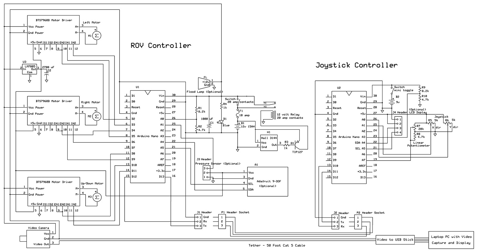
FIGURE 1. Complete schematic of both circuit boards and their connections.
The electronics components that go into the main tube are mounted on a 1/4 inch piece of Plexiglas that is 4-1/2 inches wide and 14 inches long. At the front is the video camera with a power distribution buss just behind it. The camera can be any small version that puts out a standard NTSC signal, or PAL if you are in many other parts of the world. One that runs on 12 volts will make things convenient. Topside, the video signal is fed into an inexpensive analog video to USB stick. This device comes with simple viewing and capture software that runs on a laptop.
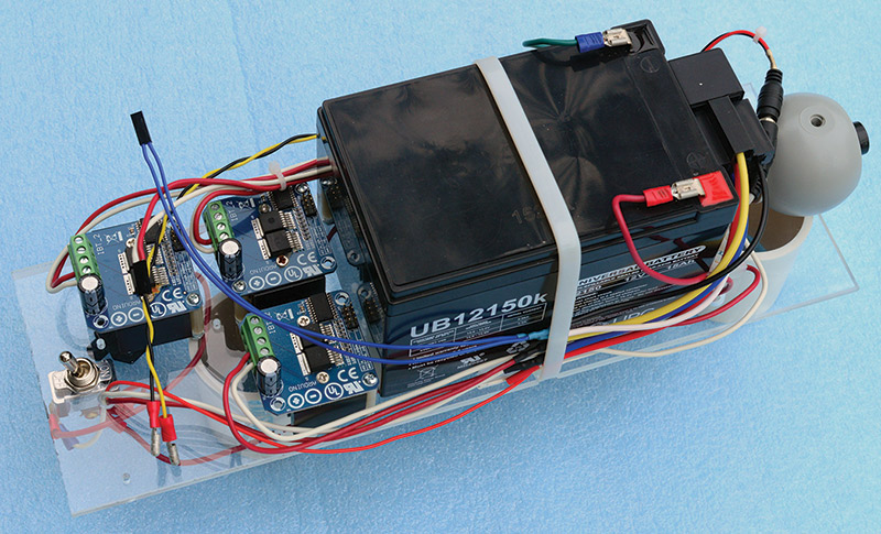
FIGURE 2. Electronics package without the Arduino controller board.
Next in line is the 12 volt sealed lead acid battery. Do not use a battery that is not sealed or you are asking for acid spills. I cemented a couple of small pieces of Plexiglas to the larger piece to keep the battery from moving, and then tied it down with a large nylon wire wrap.
Behind the battery are the three motor drivers and the Arduino Nano controller printed circuit board (PCB). How and where these components are placed will depend on the size of motor drivers you use. There is plenty of room for the various parts, and small shelves could be built here to house additional or differently shaped parts.
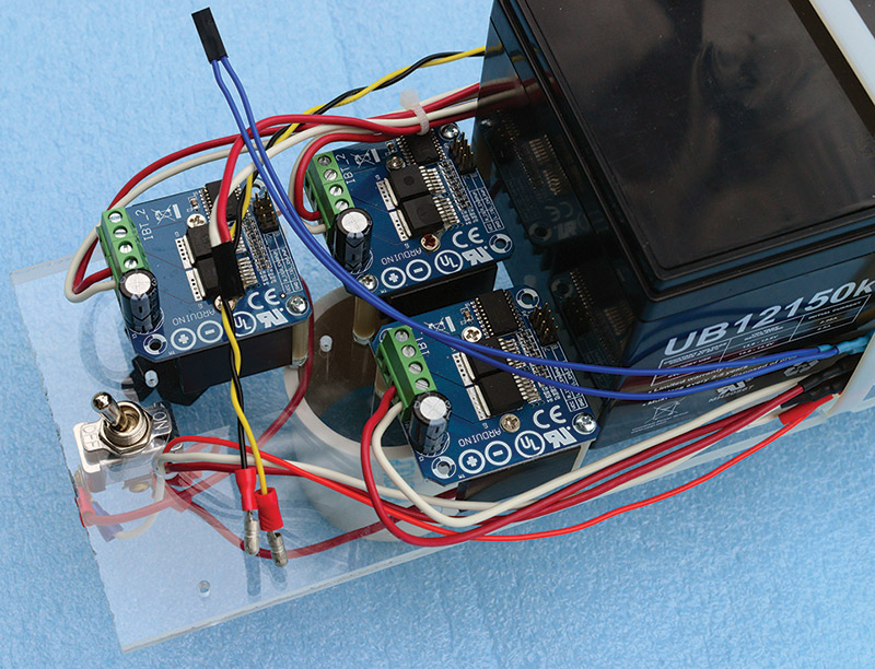
FIGURE 3. Close-up of the motor driver boards.
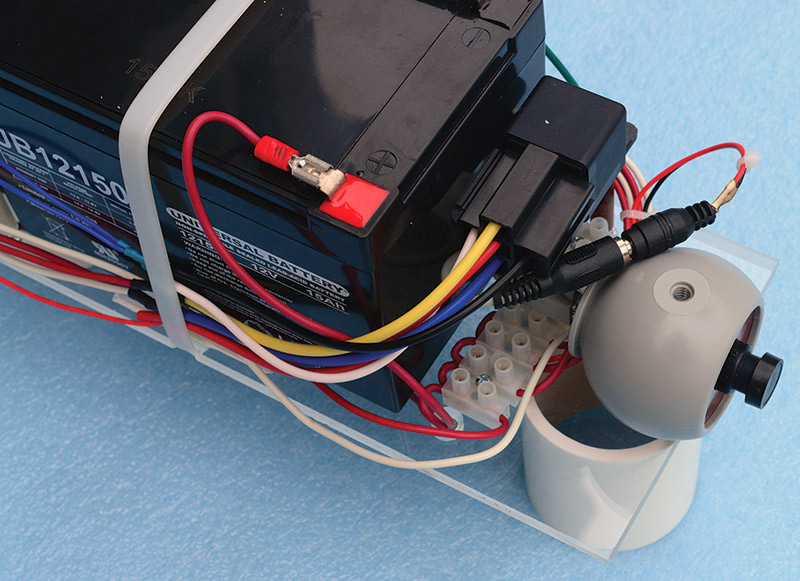
FIGURE 4. Close-up of the video camera and power relay.
The BTS7960B motor drivers use an eight-pin control header. These were cabled to identical headers mounted on the Arduino board. It was easier to obtain short four-pin jumper cables; two of these are connected to each motor driver. The four power connections (two to the 12 volt battery and two to the motor) on the motor drivers use convenient screw-down connectors. A power switch was also mounted at this end, along with a small 18 amp circuit breaker (or fuse) for when/if things go wrong.
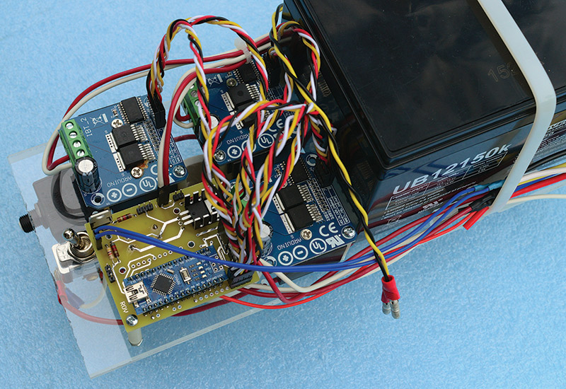
FIGURE 5. Close-up with the Arduino controller board and jumpers to the motor drivers.
The Arduino Nano Controller PCB
Both the Arduino Nano controller board and the Arduino Nano joystick board are laid out on a single ExpressPCB MiniBoard. ExpressPCB (www.expresspcb.com) will produce three of these MiniBoards for about $65. You might want to share the cost with a couple of friends. After receiving my boards, I cut the two apart, having left space for this in the layout.
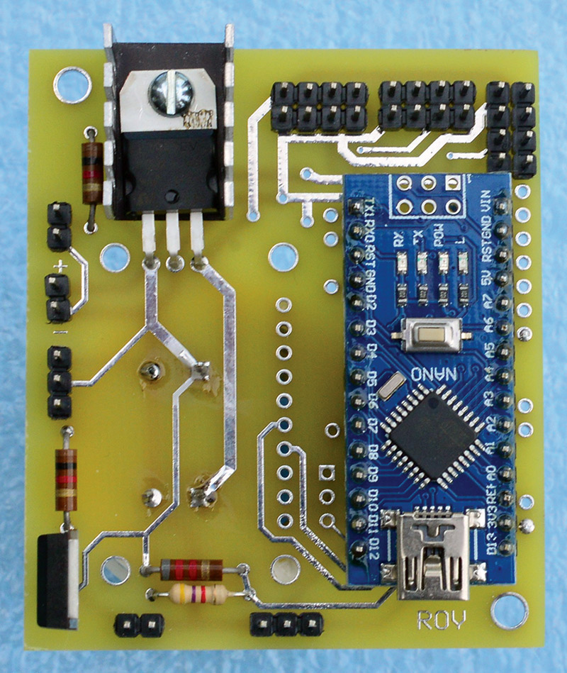
FIGURE 6. The Arduino controller boards without optional Adafruit 9DOF board.
This controller board contains the Arduino Nano, and the connections from its pins to the headers where jumpers make connections to the motor drivers. A 7805 five volt regulator provides the power for the five volt logic of the three motor drivers and any additional sensors (such as pressure, compass, or an accelerometer).
Both the 12 volt and five volt lines have large filter capacitors to remove noise, and are mounted on the bottom of the PCB. The additional Hall-effect switch components are also mounted on this board. One inch standoffs are just the right height for mounting the controller board and the motor drivers.
Note: The connection shown on the board in Figure 1 from the onboard 12 volt line to the Hall-effect switch circuit is in error. This has been corrected on the included ExpressPCB circuit board layout. This circuit must be powered directly from the 12 volt battery and must always be live. A simple circuit pad is connected to the center pin of the Hall-effect switch header and the emitter of the TIP127. This circuit pad is then wired directly to 12 volts from the battery.
The Arduino Nano Joystick PCB
This PCB is quite simple. It only contains the Nano and header pins to connect to the small joystick and linear potentiometer. Since the linear potentiometer I had was audio taper, I placed a resistor in parallel with the wiper and ground end to produce a more linear change in resistance.
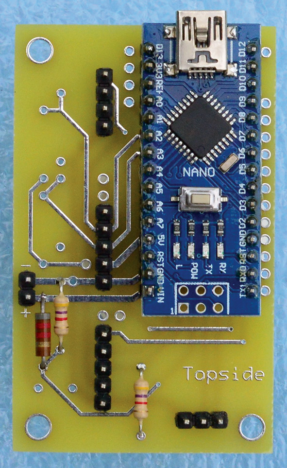
FIGURE 7. The Arduino joystick board.
I also added a two resistor voltage divider so the battery voltage could be read. The plastic box containing this board also mounts the joystick, linear potentiometer, power switch, and video output jack.
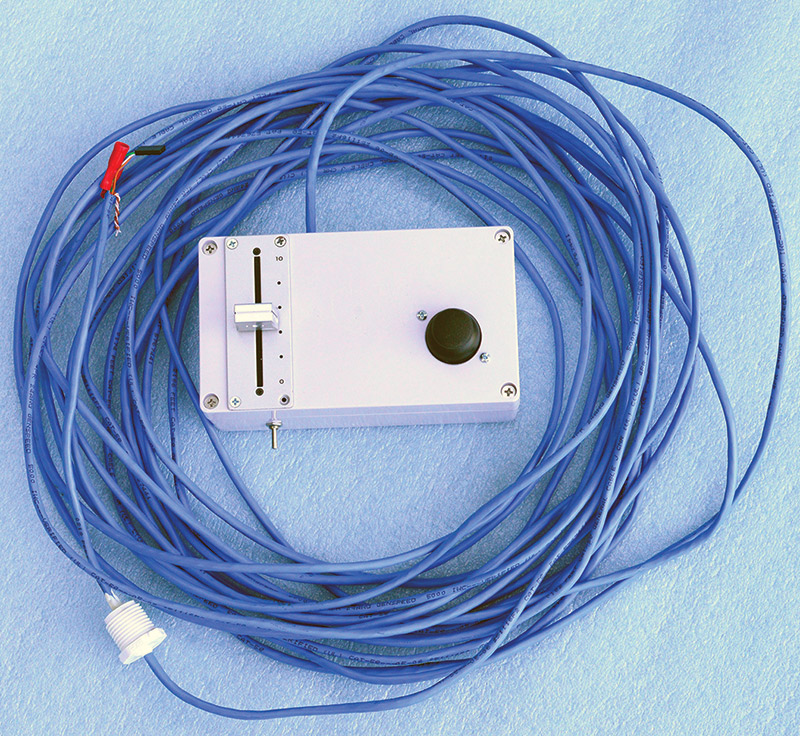
FIGURE 8. The joystick box with mini joystick, slider potentiometer, power switch, and 50 foot tether.
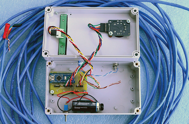
FIGURE 9. The inside of the joystick box.
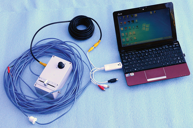
FIGURE 10. Joystick box with video connected to the USB stick in the laptop.
Optional Circuitry
Both of the PCBs have places to mount additional optional circuitry. These optional pieces are marked as such on the schematic. This includes a header for an LCD display on the joystick board and a header for a pressure gauge and pads for an Adafruit 9DOF board on the controller board. A flood lamp is also shown on the schematic which was directly wired into the 12 volt power. Arduino code for these options has not been added to the controller and joystick programs; however, there are some code fragments presented for these devices under the Optional Components section in the final installment.
Next time, we will tackle the software. Two different Arduino programs are used to run the controller and joystick boards.
If you are eager to get started, you can look at the two complete programs in the download section from Part 1. SV
Article Comments