
Servo Magazine ( October 2017 )
The Lynxmotion Quadrino Nano Flight Controller
By John Leeman View In Digital Edition
There is a plethora of flight controllers on the market. Some tout their small size and low cost. Others offer advanced flight planning functionality. Yet others aim to target the true tinkerer with open source firmware that can be hacked to add features. I was thrilled when RobotShop offered to let me evaluate their Lynxmotion Quadrino Nano flight controller module. This flight controller hits many of the check boxes for most hobbyists in a tiny package. Let's unbox and install the Quadrino on our homebuilt quad, and play with some of the settings to get into the air.
The Quadrino is a pretty powerful little flight controller, packing an ATmega 2560, inertial measurement unit (IMU), barometer, and GPS on board. The flight controller also offers plenty of expansion ports. There are I/O headers to interact with the ATmega, and two I2C and three UART ports exposed! Everything from sonic rangers to camera triggers could be attached to these ports.
Unboxing
After UPS dropped off the box at my doorstep, I immediately cut into it and was surprised to find a hard plastic case inside. Yes, the nano comes packaged in a hard case with custom foam inserts! This was instantly a treat compared to the crushed cardboard boxes our electronics so often show up in. Inside the box is a set of cables for the drone, USB micro cable, GPS, a few tools, double-stick tape, flight controller, connector chart card, and Lynxmotion sticker (Figure 1).
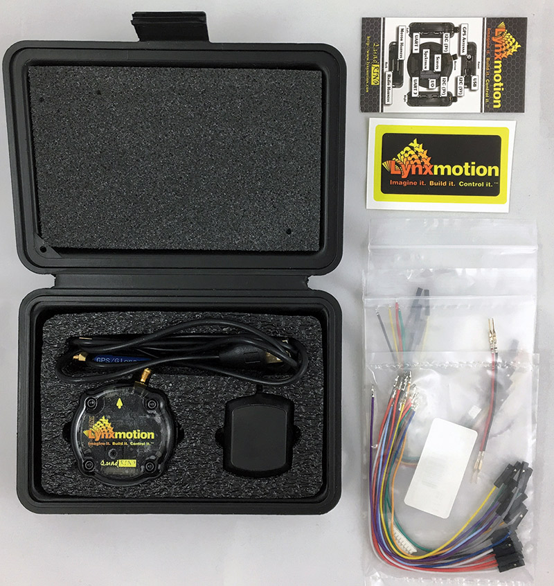
FIGURE 1. The flight controller comes in a nicely formed ABS case with all the cables grouped by function, and a handy reference card for the flight controller’s ports.
After pulling out the foam, the rest of the goodies come out and can be laid out on your bench (Figure 2).
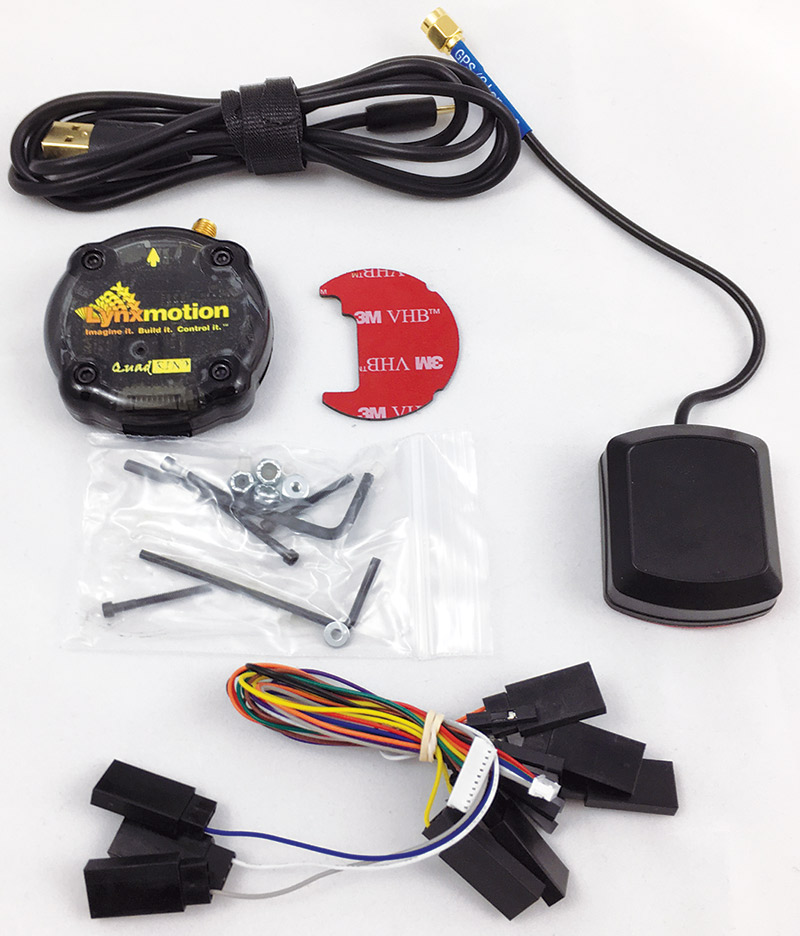
FIGURE 2. Digging into the case further, you’ll find a hardware kit, double-stick tape, USB cable, and ESC wiring.
I have to say, that the attention to detail in the packaging was really nice, and it’s good to know when switching out flight controllers for testing (as often happens), there is a safe place for the Quadrino to live.
Looking at the nano, you can see it’s only about the diameter of a can of soda. There are connectors on the sides as well as the bottom of the unit (Figures 3 and 4).
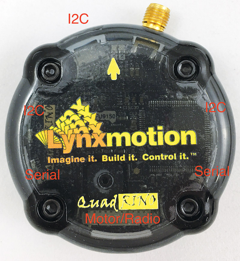
FIGURE 3. There are two serial ports and three I2C busses available to the hacker for modifying the flight controller.
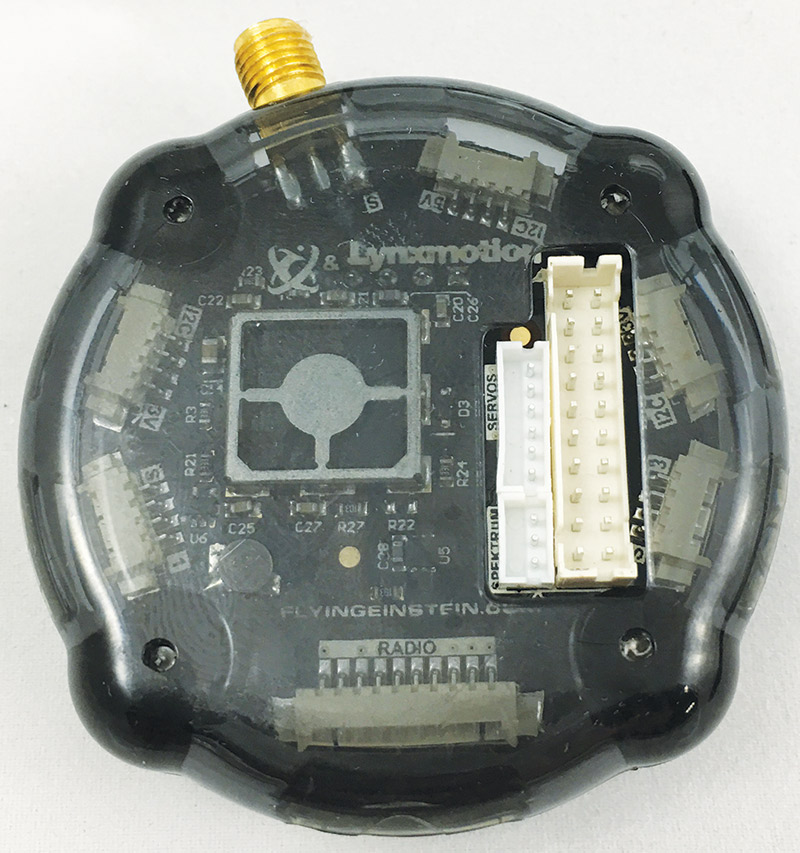
FIGURE 4. The bottom of the flight controller has even more expansion options, with as many GPIOs as you could want.
The case is translucent so that status LEDs can be seen without the need for light pipes or external indicators. The only connector sticking out is the SMA connection for the GPS antenna.
Opening up the case (as Dave Jones of the EEVBlog would say — Don’t turn it on, take it apart!) shows a very tightly routed PCB (printed circuit board) with a lot packed into a small package (Figure 5). All of the connectors are nicely made and seemed pretty rugged.
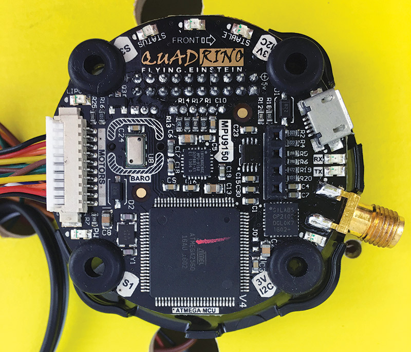
FIGURE 5. Black solder mask makes it difficult to see the traces, but the PCB is well laid out with great silkscreen legends to help identify the ports and chips on board.
Installation
The first step to installing the Quadrino was to remove the OpenPilot flight controller I had previously installed on the quad (Figure 6).
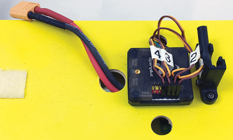
FIGURE 6. The OpenPilot flight controller has a similar footprint, but has proven to be less developed than I’d hoped. I’m saving this controller for another project though!
I was never very happy with the magnetometer on this flight controller and had no luck getting GPS controlled missions to work correctly. I pulled it off, then used a knife and alcohol to remove any residue from the double-stick tape. I also unbolted the GPS mast mount and put all of these into my drone parts tub.
While the basic hookup does not use the bottom connectors of the flight controller, I’m sure that I’ll want to experiment with them at some point. The flight controller can be bolted to an airframe, mounted with an available RobotShop mounting kit, or stuck down with double-stick tape. I elected to use the tape, but with no space for wires to exit the bottom of the flight controller, I needed a cutout in the flight deck of the quad.
I centered the flight controller on the quad and marked its perimeter on the side with the connectors. Be sure to check that the forward arrow is indeed facing the front of the craft!
Using calipers, I measured the offset of the connectors and drew the outline on the wood. You could also photocopy the bottom of the flight controller and use that to transfer the pattern.
To create this odd-shaped cutout, I used a few simple tools and some elbow grease. First, I used a small step drill and my drill press to hog out most of the central material (Figure 7).
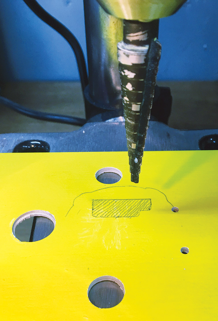
FIGURE 7. Using a step drill bit makes it quick and easy to hog out the majority of material in the cutout area for the bottom connectors of the flight controller. Be sure to wear proper PPE!
I drilled a series of holes, and just kept drilling larger and larger until I was touching one of the boundaries. Just doing that, I was able to get most of the wood removed (Figure 8).
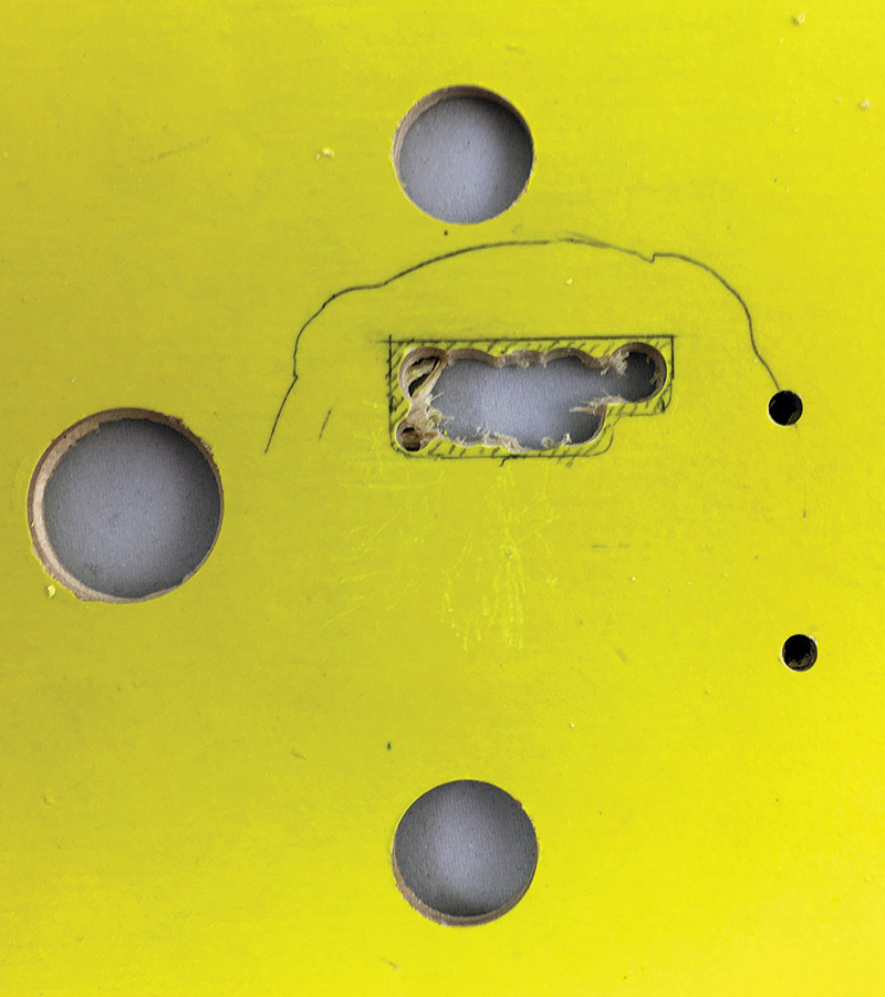
FIGURE 8. Hogging out material with the step drill got the hole into a usable form, but it looks horrible. Using a file, the corners can be cleaned up and the last bits of wood removed.
After getting most of the material out of the way, I used a set of small files to bring the hole into shape and square things up.
While this hole won’t be seen from the top of the quad, I wanted it to be tidy (Figure 9).
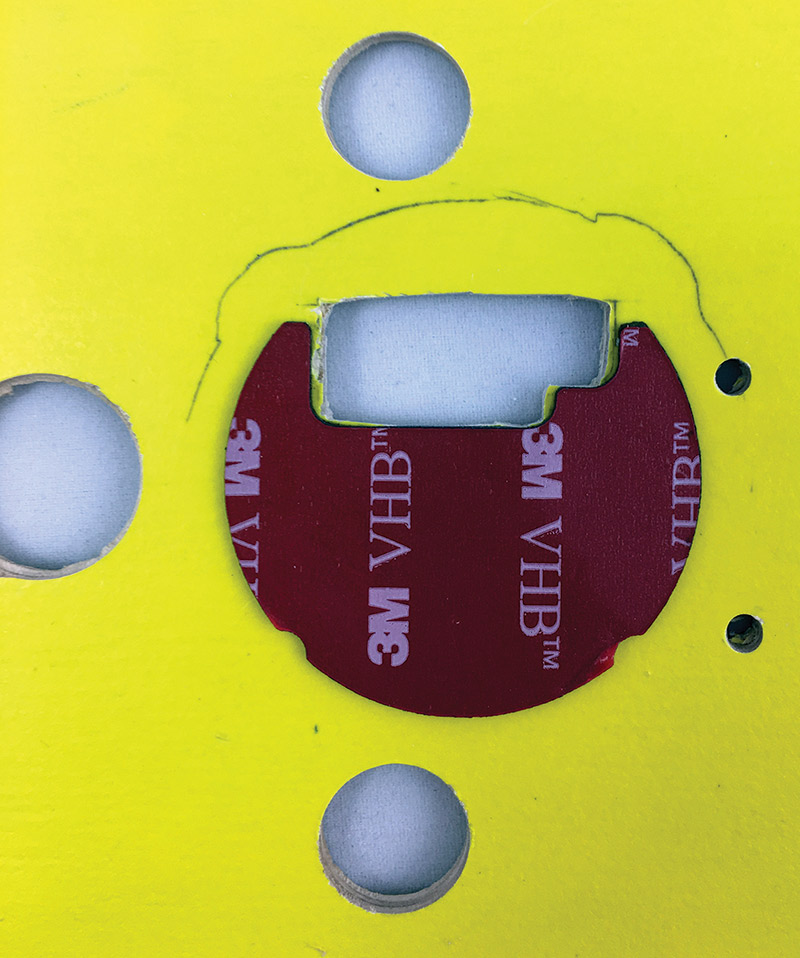
FIGURE 9. After filing out the last bits of wood, I aligned and applied the double-stick pad. This material is incredibly sticky — you’ll only get one shot!
After checking that everything lined up, I peeled off one side of the double-stick pad and stuck it down to the flight deck. I peeled the other side of the tape off and carefully stuck down the flight controller (Figure 10).
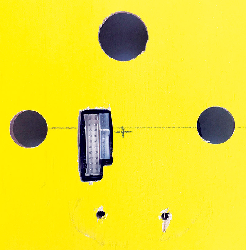
FIGURE 10. The bottom connectors lined up nicely with the hole. Be sure to leave some extra room so the connectors can be installed and removed without too much headache.
You can buy a three pack of these custom cut tape pieces from RobotShop if you need to remove the controller multiple times. For the price, I’d say it’s worth it to save yourself the half hour of trimming away strips of tape.
Now that the flight controller was mounted, it was time to wire it up!
Hookup
Like any other flight controller, the Quadrino takes signals from an RC receiver module, interprets them, combines the control inputs with the state data of the craft, then effects changes in the motor control outputs to modify the craft’s attitude. This isn’t all that dissimilar from commercial “fly-by-wire” systems in which pilots no longer manipulate the control surfaces of aircraft, but provide inputs to a flight control system that maintains the stability of the aircraft during the maneuver and eases pilot strain. To get our flight controller up and running — at a minimum — we need to connect it to the RC receiver and electronic speed controllers (ESCs).
The channel layout on your receiver may vary depending on the brand and transmitter setup. In the quick start guide, a color-coded hookup guide is provided (Figure 11).
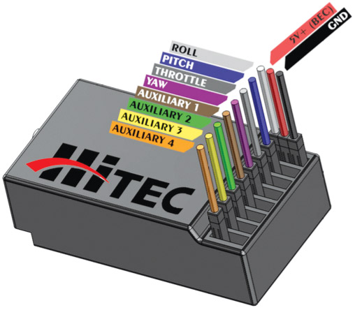
FIGURE 11. The user’s guide shows a relatively common hookup pattern for RC receivers. I recommend verifying your receiver’s channel order with a servo and some quick checks. (Image courtesy RobotShop.com.)
I experimented using a servo as a handy indicator and found that the sequence on my Turnigy receiver matched that shown in the diagram, but mirrored.
Remember that the signal connection is generally the top- or left-most connection; positive the center; and ground the right or bottom. Hook up the eight signal wires and the power and ground wires from the flight controller harness to your receiver (Figure 12).
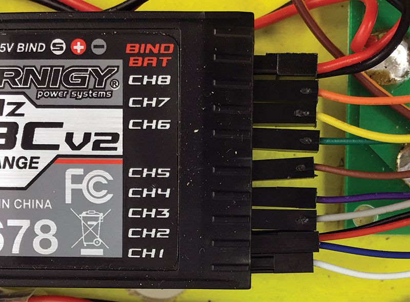
FIGURE 12. Hookup of the Turnigy receiver was straightforward. For those modifying the H-quad, the hookup order should be identical.
Next, we’ll connect the ESC control harness. Since the most popular design is a quadcopter, the connector comes with four ESC connections ready to go. There are four more connectors in the kit that can be inserted into the connector if you are building a hex or octocopter. The ESC controls are numbered by what I believe to be pin numbers on the microcontroller. This is not incredibly intuitive as the available motor numbers are 2, 3, 5, 6, 7, 8, 9, and 10 (Figure 13).
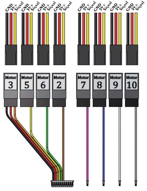
FIGURE 13. The ESC motor numbering is slightly odd, but I believe corresponds to pin numbers on the microcontroller. If your quad has more than four motors, you can insert the appropriate wires into the motor connector housing. (Image courtesy RobotShop.com.)
Find your quad configuration in Figure 14 and note the motor number, direction, and position with respect to the forward direction.
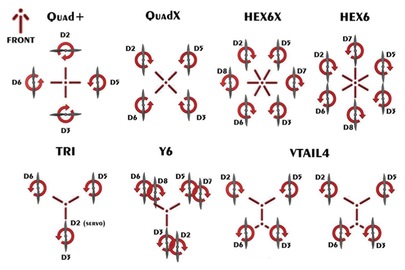
FIGURE 14. Find your quad configuration on this chart and hook up the motors accordingly. Even though my quad is an H frame, the X-Quad configuration is the same. (Image courtesy RobotShop.com.)
For our homemade quad, we’ll use the QuadX configuration. Even though the design is technically an H-quad, the X version looks the same to a flight controller as the forward direction is between two propellers, not aligned with one of them (the plus configuration).
I found it easiest to connect the ESCs to the connector and then feed it through the flight deck to connect to the flight controller. You may be able to connect the cable with the flight controller case assembled, but I had a hard time. I found it easier to remove the four screws holding the top of the case on and connecting up the cable. It also gives you a chance to have a look at the PCB layout (though not easy to see with a black silkscreen). As regular readers know, I love seeing other people’s layouts and tricks.
That’s all there is to connecting the basics for flight. For those who want to tinker, remember that there are UART and I2C ports on the sides of the flight controller (Figure 15), as well as GPIO on the bottom (Figure 16).
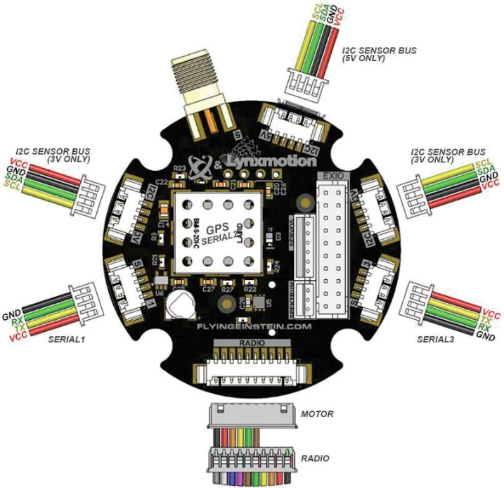
FIGURE 15. The expansion ports on the flight controller leave little to be desired. There are 3V and 5V I2C busses, as well as two serial ports. This makes connecting just about any sensor possible. (Image courtesy RobotShop.com.)
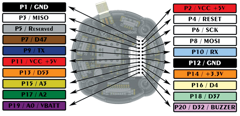
FIGURE 16. Connectors on the bottom of the flight controller provide GPIO pins for further hacking and modification. This connector also houses the battery voltage sensing pin. (Image courtesy RobotShop.com.)
Firmware Setup
Setting up the firmware of the flight controller was not very well documented as it appears that the procedure has changed some recently, but it was not beyond an afternoon’s worth of experimentation. First, we need to set up the firmware parameters for the flight controller and Flash it; then we can finish configuration with the ground station tool.
Download the Quadrino Firmware Configuration Tool (FCT) installer from the Flying Einstein website (https://flyingeinstein.com/installer/fct/setup.exe) and go through the install procedure. This tool appears to be Windows specific, but I was able to run it on my Microsoft Surface running Windows 10.
Once installed and launched, the first screen asks for a drone profile name and MultiWii version. I created a new profile and named it for my quad to keep things straight. MultiWii 2.4 was the only option (Figure 17).
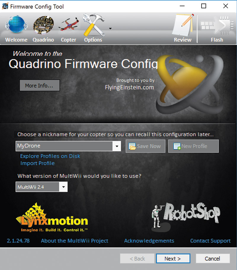
FIGURE 17. Create a new profile for your drone to save the settings locally so you don’t have to continually reset the same parameters as you play with the firmware options.
Next, we find ourselves at the Quadrino configuration screen. Again, here most of the drop-down menus have only one option. We have the Nano V1. The sensors (gyro, accelerometer, magnetometer, and barometer) addresses are pre-populated for the flight controller’s setup.
The next screens ask questions about our copter configuration. Here is where we select QuadX for the type of multirotor. There are also settings for the minimum and maximum PWM (pulse-width modulation) outputs for the motor ESCs. I found the defaults worked well, but they can be tweaked slightly to ensure there is no cogging at slow speeds, and that the motors completely shut down at minimum throttle.
There are also a number of settings to define the size of your quad and how you’d like it to fly. If you’re unsure, leave the defaults. Since I fly sensor platforms mostly, I’m more interested in passive and stable flight, but adjust as you’d like. Do be sure to measure and set your frame size (distance between motors) and aspect ratio.
Finally, we get to all the options and tweaks for the flight controller. Most of these can be left at their defaults, but taking the time to go through and customize the firmware is worthwhile.
The Flight tab had defaults that were fine for my setup (Figure 18).
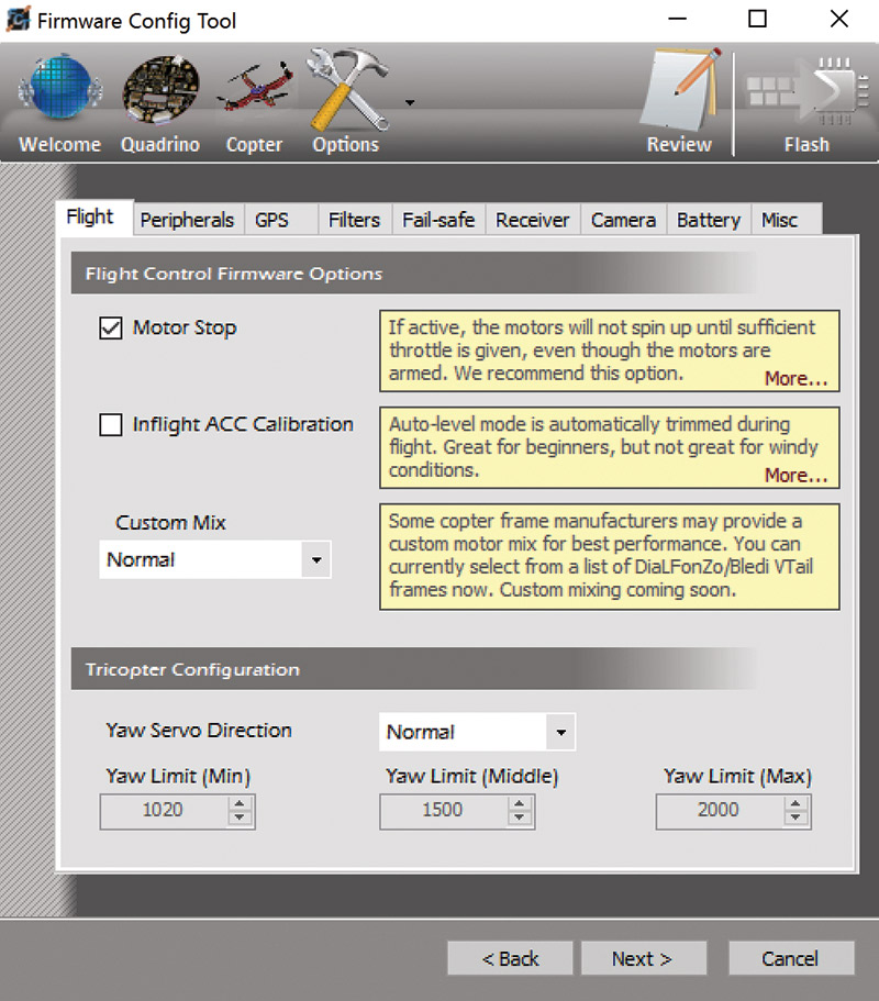
FIGURE 18. The Flight tab defaults are good for an initial run at the settings. I would be interested to try the inflight accelerometer calibration, but found the performance was fine without it.
The Peripherals tab lets you enable an ultrasonic altitude sensor, status LCD, or LED ring to indicate status and direction (Figure 19).
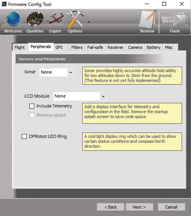
FIGURE 19. Several peripherals have built-in support including ping altitude sensors, LCDs, and LED rings. I can see all being useful for advanced fliers or making the drone showy with bright lights.
These were all disabled by default, which is fine with the stock setup. The GPS tab is where we start making changes.
We need to select the QuadrinoNanoWithGPS option. Leave the port and baud rate at their defaults. We also want to turn on the five-satellite lock indicator and enable waypoints (Figure 20).
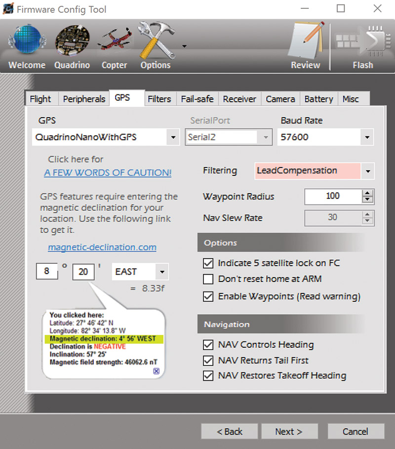
FIGURE 20. I enabled the GPS and waypoint navigation to try planned missions. Be sure to read the words of caution in this dialog box and set the magnetic declination.
Make sure you read the caution link about enabling waypoints and GPS!
We also need to set the magnetic declination of our location so the flight control algorithm can resolve the magnetic and GPS headings when computing courses. Head over to www.magnetic-declination.com and enter your city. In the pop-up on the Google map, you’ll see the declination of your location. Pay special attention to the sign of the declination (Figure 21)! Enter this into the menu.
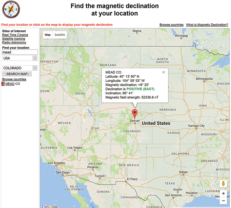
FIGURE 21. The website magnetic-declination.com has a very simple interface to find the declination at your location. Be sure to note the sign of the declination as well as the value.
The Filters tab lets you modify the filtering of acceleration and gyro data. I’m assuming that this is a low-pass filter to help eliminate noise from vibration, but as the dialog box points out, it’s best to try to eliminate the source of vibration in the first place! Unless you have a good reason or have issues, leave the filter corner at the default of 98 Hz (Figure 22).
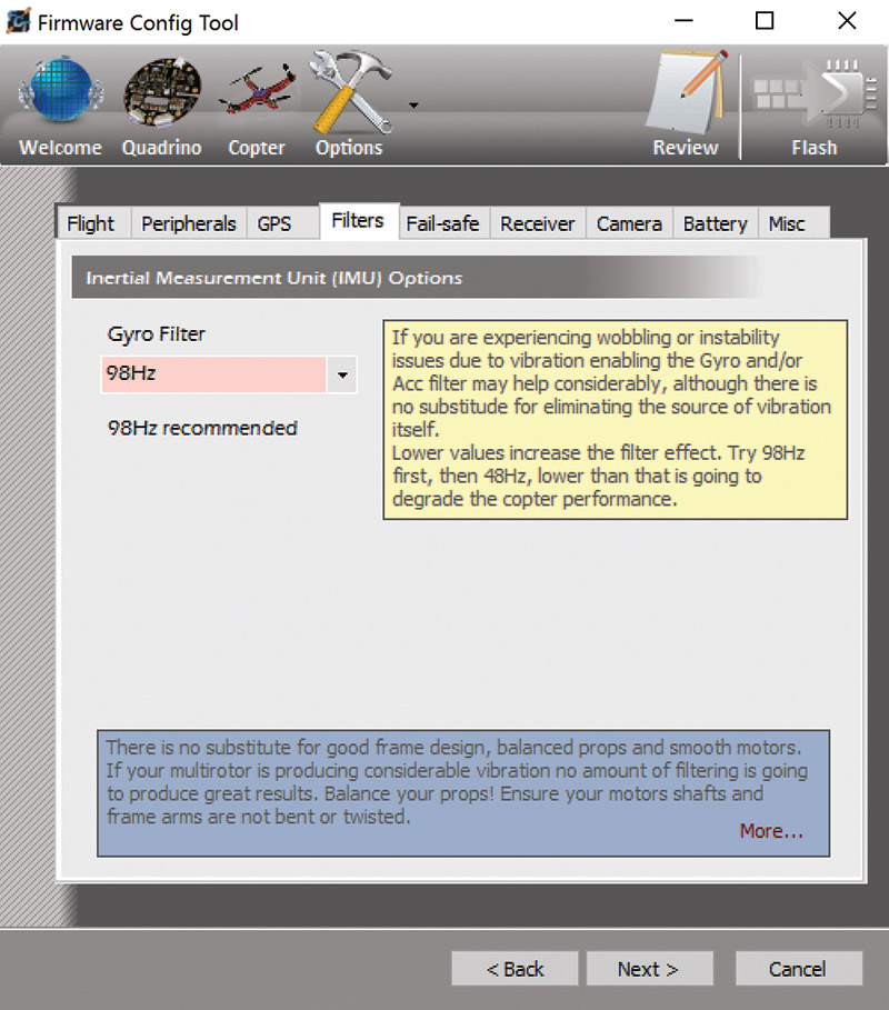
FIGURE 22. I found no issues with the default 98 Hz filter on the IMU, but if you are having instability issues, consider making the filter more aggressive.
The Fail-safe tab configures the behavior of the flight controller if the signal from the RC transmitter is lost. I enabled this with a five second delay. The off delay setting determines how long the motors will run at the set power before shutting off.
With the configuration shown, the motors would run at half throttle for 20 seconds (Figure 23).
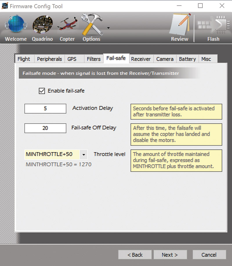
FIGURE 23. Fail-safes are a great way to keep your quad from flying off in the event of a control signal loss. Ideally, this fail-safe will bring the quad down gently instead of falling from the sky at terminal velocity!
This would be a slow descent for my quad. Hopefully, the quad would be close to or on the ground by the time the motors shut off. This is a nice feature that should help prevent fly-aways, which are always a worry.
Next, the receiver is configured. Since I’m using the more traditional style receiver with multiple PWM servo connections, I selected StandardPCM as the receiver protocol, but select whichever is appropriate for your system. I left the rest of these settings as the defaults (Figure 24).
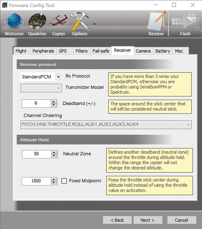
FIGURE 24. My receiver is of the StandardPCM type, but those with Spectrum or other more advanced receivers will need to adjust this tab as necessary.
I also left the defaults (off) for the camera and battery monitoring setting tabs. While the battery monitoring is a nice feature to have, I wanted to get running with the most basic setup before adding bells and whistles. Note that for the battery monitoring to work, you need to connect the battery voltage sense lead to your power distribution board somewhere.
Finally, accept the defaults on the Misc tab (Figure 25).
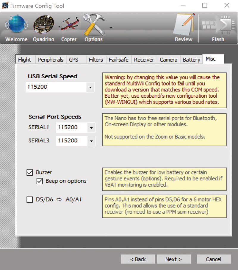
FIGURE 25. The Misc tab allows you to change the baud rate of the serial ports. Unless you have a good reason, leave all of these at 115200.
If you are connecting sensors or other microcontrollers to the two free serial ports of the Quadrino, you can modify the baud rate here. Make sure you leave the Quadrino at the default 115200; otherwise, the firmware configuration tool will be unable to communicate.
The next screen is a bit misleading as there is a finish button, but clicking it exits the program. First, click the Flash firmware button and watch as the firmware compiles and is transferred to the Quadrino. After a successful Flash of the firmware, click finish to save your settings and close out the firmware tool (Figure 26).
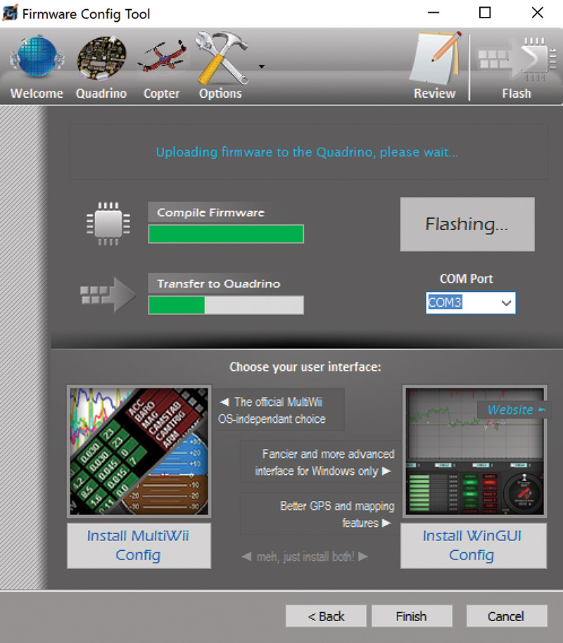
FIGURE 26. Don’t forget to click the Flash button before clicking Finish! Flashing takes about 20 seconds.
At this point, I powered up the copter and was planning to use the ground station software to finish setting up my controller and go on a test flight. As soon as I plugged in my flight battery, all of the ESCs began beeping that they needed calibration. Unfortunately, this is not an easy process.
There is a calibration firmware that can be uploaded and will (in theory) calibrate all ESCs at once, but it did not work after Flashing. So, I won’t go into the upload process. I ended up removing each ESC’s control wire from the flight controller, connecting it to the throttle channel of the receiver, and manually calibrating each ESC. While only a 10 minute job on a quad, it could be much more troublesome on a hex or octocopter. If you need a refresher on ESC calibration, be sure to read my previous ESC basics article.
After calibrating all of the ESCs and quieting the storm of beeps, I installed the WinGUI software that makes up the ground station and flight mode configuration. This is a Windows only solution. The MultiWii software is available cross platform, but I found it much harder to use and not compatible with the high resolution screens of many modern laptops (such as the Microsoft Surface).
There are myriad settings in WinGUI, but the only settings we need to worry about are under the RC Control Settings tab (Figure 27).
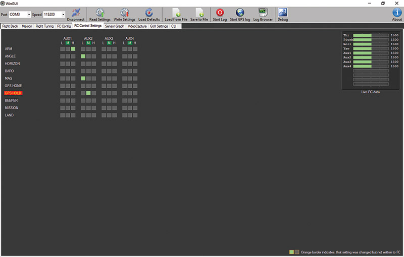
FIGURE 27. The RC Control Settings tab shows the active switch positions and flight modes in a matrix of colored chicklet indicators. I’ve experimented with many of these modes, but found angle coupled with mag to be a nice configuration.
Here, we set what flight mode the system will operate in and how the system is armed.
I used a three-position switch on my controller to set the flight mode, and a two-position switch to arm and disarm the system.
The online instructions indicate that a stick pattern is used to arm the flight controller — much like the original OpenPilot system. However, I believe that is a relic of past firmware as it did not arm the current system.
As far as flight modes go, I elected to operate in angle + mag mode by default. This is similar to the stabilized mode of the Parallax ELEV-8 — an easy-to-fly configuration. I used a magnetic heading mode as one, which should hold the craft in a constant magnetic heading (unless acted upon by the yaw control) and land.
I did really like that you could see the position of each switch on the controller via the color changing boxes. This made it easy for me to confirm which mode would be active with which switch position. Note that when settings are changed, the outline of the box turns orange, indicating that the settings have not been written to the flight controller. Make sure you save and write these settings!
Before flying, we also need to calibrate the accelerometer and magnetometer in the Quadrino. This is done with buttons on the Flight Deck panel (Figure 28).
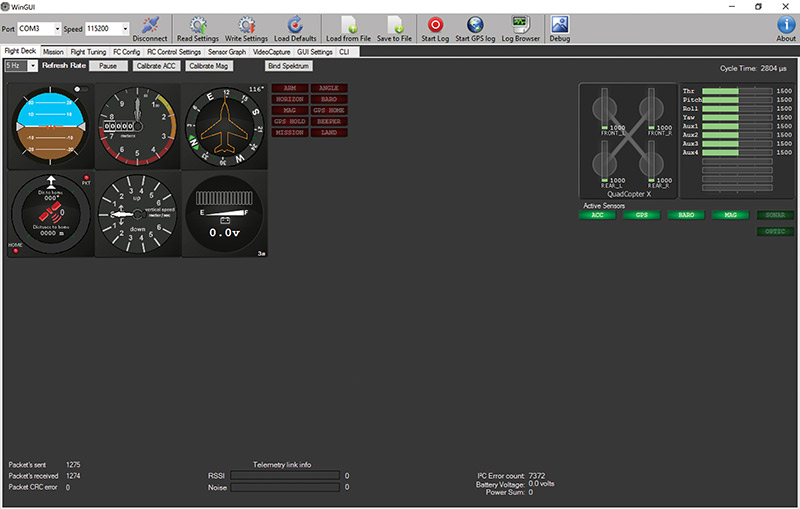
FIGURE 28. The Flight Deck tab shows the traditional cockpit instruments and provides options to calibrate the IMU sensors.
When the Calibrate ACC button is pressed, you must leave the craft stationary for about 30 seconds while the axes are read and compensation is applied for any errors introduced through the orientation of the flight controller on the airframe.
When calibrating the magnetometer, you are prompted to rotate the craft slowly around all three principal axes. This allows the magnetometer to calculate its hard/soft iron corrections and offsets to maximize its accuracy.
Flying with the Quadrino
Now that everything is calibrated and properly set up, you should see a flight deck display that shows the orientation and heading of your craft accurately, and moves appropriately if you tilt or rotate the craft. (A common point of confusion is the artificial horizon. Remember, the brown represents the ground. So, in a right bank, the right side of the indicator will rise.)
I powered up the quad, armed the fight controller, and gently eased the throttle up. I did get off the ground, but noted that I was drifting around quite a bit. After some trim adjustments on the controller, I was able to achieve stable flight and maneuver around nicely. I flew a short circuit around the field, and then brought the quad to a hover about two meters off the ground and flipped the flight mode switch to put the quad into the magnetic heading mode. For the most part, the heading was constant, but I noticed drift that was possibly due to a trim adjustment.
As I was fiddling with the controller, the quad’s port rear motor lost power and I came down on that boom. The only real damage was a lost propeller (Figure 29), but I have not figured out what caused the glitch.
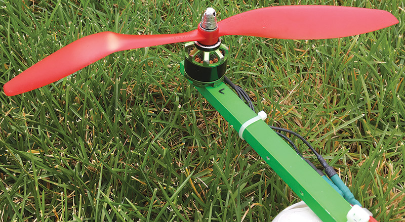
FIGURE 29. Luckily, after a strange crash in which a single motor quit, the only damage was a bent propeller. A quick prop change and it was back to flying!
I suspected a loose connection on the ESC, so I tightened up those connectors and have flown since with no issues.
The overall flying experience with the Quadrino is very pleasant. It flies nicely, but suffers some from the slightly complex setup and lack of auto control range sensing (hence, all of the trimming). With an improved firmware configuration and ground station software, it would be an even better product.
I was excited to try GPS flight planning, but was only able to get a GPS lock once, then the controller never saw another satellite. I’m in the process of troubleshooting why the GPS will not lock and will then share my flight planning experiences with you. I’m particularly excited about flight planning to simplify data collection missions (like our IR mapping project) and allow a more hands-off flying experience.
Closing Thoughts
In the end, I thought the Quadrino was a really nice product with a very small form factor. It’s lightweight and has lots of versatility for the hacker/maker (Figure 30).
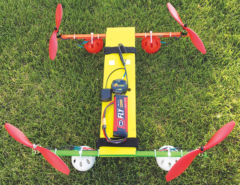
FIGURE 30. Overall, the Quadrino is a nice flight controller with lots of possibilities. It is designed for the hacker and experimenter that wants to dig in and customize their copter with new sensors, code, and a lot of knobs to adjust.
I’d really like to see more and updated documentation to make the initial setup experience easier.
As I mentioned earlier, an automatic control range determination like that of Open/LibrePilot would also ease the setup experience.
If you are looking to really modify and customize your quad, take a look at the Quadrino.
Until next time, fly safely. SV
Article Comments