Robotic Sensors - Part 2
By John Blankenship, Samuel Mishal View In Digital Edition
Last time, we saw how a robot could find and identify a ball and goal, allowing it to engage in a simplified version of soccer. This time, we'll examine how the principles of identification used with the soccer robot can allow a mobile robot to find and retrieve objects with a simple robot arm and then move them to a desired destination.
As mentioned previously, we used a simplified soccer-playing robot to demonstrate that a robot’s ability to cope with its environment can be improved by giving it a rudimentary ability to identify objects of importance. The ball trap on the soccer robot was essentially a non-motorized gripper, and the robot itself could be thought of as a robotic arm with one degree of freedom. Because of these similarities, it makes sense to expand on principles discussed last time by applying them to a more capable robotic arm.
Before we begin though, we need to examine robotic arms themselves. If you search the ’net for robotic arm images, you will find hundreds of arms that are suitable for the robot hobbyist. In almost every case though, the arms have a major flaw — the arms and grippers have little — if any — sensory capability. What’s worse is that most arms have not even been designed to allow sensors to be easily added.
This limits the arm’s activity to pick-and-place maneuvers where the objects to be manipulated are assumed to be found at specific positions, sometimes with specific orientations. Industrial assembly lines can often make such assumptions, but a hobby arm — like most hobby robots — needs sensors to properly interact with its environment.
The lack of sensors may seem acceptable at first, because most low cost arms utilize servomotors to power their joints, allowing the arm to be positioned without the need for sensory feedback. This is not unreasonable as long as maximum loads are not exceeded, plus it has significant cost advantages. High-end digital servomotors — such as Dynamixels — have built-in sensory capabilities that can provide information about the position and load associated with an arm joint.
However, this does not eliminate the need for gripper-mounted sensors that can be used to guide and control the arm’s movements.
The arm’s movement itself brings up another important point: Nearly all robotic arms have the motors that control the joints mounted on the arm itself. This causes two problems. The arm’s lifting ability is diminished by the weight of the motors, and the movement of some joints can affect the orientation of others.
Figure 1 demonstrates this point by showing that joint angles are relative to the position of other joints.
![]()
FIGURE 1.
As you can see, when the shoulder joint is moved, the angles of the other two joints (when referenced to ground) change dramatically.
When arms are built this way, a significant amount of mathematics is required to determine the angle each joint should have in order to create a desired position and orientation of the gripper.
Furthermore, if you want to keep the gripper level during some maneuver, for example, the elbow and wrist joints have to constantly be manipulated during shoulder joint movements.
If the motors are moved off the arm — as in a man-sized arm we built for another project (see Figure 2) — the orientation of each joint becomes independent of the other joints, and we get the added benefit that the arm does not have to lift its own motors.
![]()
FIGURE 2.
All the joint motors are mounted behind the shoulder joint, and a belt system delivers power to each of the joints a shown in Figure 3.
![]()
FIGURE 3.
Easy Programming
If you program an arm built with the principles shown in Figure 3, you quickly appreciate its advantages. If you move the wrist joint to a level position, for example, it will remain level no matter how you move any of the other joints. It would be nice if some manufacturer would offer a similar design, but for now you will have to build your own.
We have provided details on the construction of this arm in the RROS manual (download at https://www.robotbasic.org/), but we also understand that most hobbyists may not want to undertake a major construction project in order to experiment with the principles we are about to discuss.
For that reason, we also built a much smaller arm that utilizes many of the same concepts. It is much easier to build because it has only one moving joint.
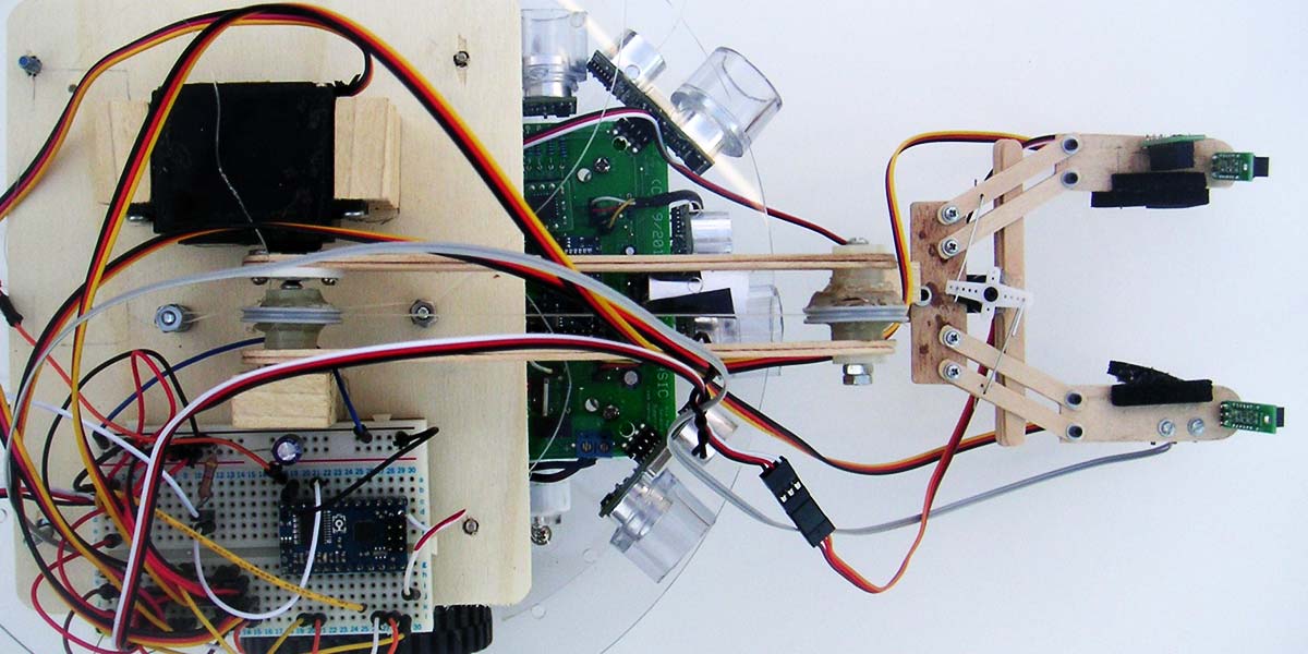
What may surprise you is that it retains much of the functionality of a far more complex version. The arm is small enough to fit on the RobotBASIC RB-9 chassis as shown in Figure 4.
![]()
FIGURE 4.
Constructing the Arm
Most of the structural components of the arm and gripper are made from various sizes of craft sticks, but you can also use Popsicle sticks and coffee stirs. Figures 5 and 6 show alternate views to provide additional detail.
![]()
FIGURE 5.
![]()
FIGURE 6.
You can also refer to Figure 7 of Part 1 which offers a clearer view since it showed the arm before the wiring was added.
Since this arm is small and lightweight, the axles for the joints are just bolts with plastic spacers serving as bearings. The wrist joint is fixed to the forearm, and the forearm maintains the position established by the two pulleys mounted on the shoulder and elbow joints.
Nylon line wraps around the elbow pulley and then around the shoulder pulley, thus ensuring the two pulleys stay in sync. The line then connects to two bolts in the base, rendering both pulleys in a fixed orientation regardless of the shoulder’s movement. This means that the shoulder joint can move at will, and yet the gripper remains level.
Construction of the gripper can be tricky. As you can see in Figure 6, the fingers are attached to the base of the hand with two struts on each side. Since these struts are equal in length, they form a parallelogram which maintains the orientation of the fingers. Actually, each strut is made from two sticks to increase stability.
The bolts at each end of the sticks serve as axles and should be used with nylon nuts so they will stay fixed without being overly tight. We added a cross-member that slides between the strut sticks for additional stability, but this is not necessary if the ends of the struts have more overlap than the base of the hand and fingers.
The nice thing about constructing with craft sticks is that they are very cheap and easy to work with, allowing you to experiment with numerous designs.
This one-motor arm is surprisingly agile. The gripper can be lowered to ground level to pick up objects and it can be raised so that objects can be placed on platforms or dropped into baskets. When the arm retracts, as in Figure 4, the gripper and any object in its grasp are out of the view of the robot’s primary perimeter sensors, including the beacon detector.
A small servomotor opens and closes the gripper as shown in Figure 6. Notice that three sensors are mounted on the fingers just as they were on the ball trap used by the soccer robot last time. Foam rubber is mounted on the inside edges of the fingers to give a better grip.
Look carefully at the finger at the bottom of Figure 6. A small snap-action switch is mounted under the finger with foam glued to its lever (you can only see the lever). Reading the state of this switch makes it easy to determine when the gripper has closed on an object.
Creating an Application
Our next step is to write a program that will allow the robot to find small objects and move them to a beacon in much the same manner as soccer robot. Most of the software Part 1 can be reused since the arrangement of the gripper sensors (when the fingers of the gripper are open) is the same as the trap. This makes the programming much easier because we only have to add the details of the arm’s movements.
Once it has been determined that an object is properly positioned in the gripper, the fingers can be closed until the snap action switch indicates that contact has been made. The amount of closure required of the servomotor serves as an indication to the size of the object being obtained.
Since objects can be distinguished by their size, the robot could be programmed, for example, to place large objects in one basket and small objects in another.
Since the shoulder joint is also a servomotor, the electronics for the arm can be any servomotor controller. Like last time, we are using the RobotBASIC RROS to control the robot, so we will also use it to control the arm. The RROS chip actually has an alternate identity. When a second RROS chip is connected to the main RROS, it can be instructed to become a servomotor controller. There are several advantages of using two RROS chips in this manner over using a conventional servo controller.
First, all the commands for servo control are automatically handled by the wireless link of the main RROS chip. Second, the RROS servo controller supplies additional analog and digital I/O lines that can be read with RobotBASIC commands. The analog inputs could be used with potentiometers to ensure that the arm joints are actually where they are suppose to be.
You could also use the analog lines to measure grip pressure or determine the color of an object held in the gripper (using appropriate photoresistors, etc.). The additional digital I/O lines are read as line sensors as in Part 1’s program.
Use Any Microcontroller
Remember, you do not have to use the RROS system (or even RobotBASIC, for that matter) to experiment with the concepts discussed. The RobotBASIC code is easy to read and well commented, so porting it to other platforms and processors should not be difficult. If you are considering using the RROS though, know that complete details of its operation are available in the downloadable RROS manual.
Figure 7 shows the complete listing for the application program.
#include "RROScommands.bas"
#Include "InitializationRoutines.bas"
gosub InitRROScommands
gosub InitRB9Chassis
main:
gosub ArmInit
gosub GetObject // find something to pickup
gosub HandClose
gosub ArmUp
gosub MoveToBeacon
gosub ArmDown
gosub HandOpen
gosub ArmUp
end
ArmInit:
rCommand(ExpansionSetup,ARM)
rCommand(SetSenseInvMask,15)
rSenseType 5 // allows more sensors
rCommand(SetServoIndex,0) // index auto-incr.
rCommand(SetServoSpeed,3) //arm
rCommand(SetServoSpeed,3) //gripper
// set minimums
rCommand(SetServoIndex,0)
rCommand(SetServoMin,150)
rCommand(SetServoMin,110)
// set maximums
rCommand(SetServoIndex,0)
rCommand(SetServoMax,45)
rCommand(SetServoMax,35)
gosub ArmHome //set home position & enable
return
ArmHome:
rCommand(SetServoIndex,0)
rCommand(SetServoPosition,0) // arm
rCommand(SetServoPosition,0) // gripper
rCommand(EnableServos,1)
delay 2000 // allow time for movement
// remove strain on the hand by
// moving the fingers slightly
rCommand(SetServoIndex,1)
rCommand(SetServoPosition,20)
return
ArmDown:
rCommand(SetServoIndex,0)
rCommand(SetServoPosition,250)
delay 2000
return
ArmUp:
rCommand(SetServoIndex,0)
rCommand(SetServoPosition,0)
delay 2000
return
HandOpen:
rCommand(SetServoIndex,1) // index for the hand
rCommand(SetServoPosition,0)
delay 2000
rCommand(SetServoPosition,20)
return
HandClose:
for HandPosition=0 to 250 step 3
rCommand(SetServoIndex,1)
rCommand(SetServoPosition,HandPosition)
rforward 0
if rSense()&8 then break // check for switch
next
//HandPosition now indicates size of object
return
FIGURE 7.
Since the listing is commented and much of it utilizes the same algorithm used by the soccer robot, an extensive explanation is not necessary. The routines GetObject and MoveToBeacon are not shown since they are the same as shown in the previous article. There are, however, a few things that should be mentioned. Let’s look first at the main program.
The GetObject routine from Part 1 allows the robot to find and move to an object. This time, we used inverted pill bottles as objects instead of the ball used previously.
Once the bottle is in the hand (based on the IR sensor that is pointed across the open fingers — just like last time), the hand is closed and the arm is raised to prevent it from interfering with other sensors. The MoveToBeacon subroutine from Part 1 moves the arm toward the beacon.
The only change we made to this routine was to force the robot to stop when something was detected by the front perimeter sensor instead of the finger sensors used previously. This was necessary because the gripper is raised to prevent interference with the beacon detector.
When the beacon is reached, the arm is lowered and the object released. The arm is then raised back to its normal position.
There are several routines that initialize the arm and perform basic arm movements. Let’s look first at the ArmInit routine. It begins by telling the main RROS chip that an external processor has been added, and that it is a second RROS chip used as an arm controller.
The next line tells the RROS to invert all four signals from the gripper sensors to indicate true when objects are detected. Next, the command rSenseType establishes that there are additional rSense() sensors (normally only three are used). The remainder of the routine initializes the arm itself.
Most commands for controlling the servomotors require an index value to specify which joint parameter is being addressed. Once set, the index automatically increments each time a command is issued, making it very efficient to control an arm with multiple motors.
Since this arm has only one joint motor, the index is constantly set back to zero in the routines. Using an index of one allows control of the gripper’s servomotor.
The RROS arm controller allows you to set a minimum and maximum point for each servomotor. Once set, the motor position (0-255) specifies a position between these limits. This means you have excellent resolution even if a particular servo only moves a small fraction of its typical 180º range.
This method also helps prevent a faulty program from moving a joint out of its preset range.
The demo program in Figure 7 allows the robot to find an object that will fit into the hand and move it to a beacon as depicted by Figure 8.
![]()
FIGURE 8.
The variable HandPosition is set in the HandClose routine. Its value represents how far the fingers were closed before the finger-mounted switch indicated pressure from the object.
You can use this value to help identify the size of the object. If desired, the object could then be moved to various places by using different beacons to identify the possible destinations.
The RROS manual explains how RobotBASIC can identify 15 different beacons.
Conclusion
This article and Part 1 have shown how sensors can be used to locate and identify objects, so they can be manipulated by a mobile robot using a simple trap or arm to acquire the object and move it to a desired destination.
After experimenting with the principles demonstrated here, we suggest adding additional sensors (such as a color sensor) to allow your robot to identify and distinguish even more objects within its environment.
Since the arm can be raised to allow full use of the robot’s perimeter sensors, this robot is ready for more complex experimentation. You could, for example, have the robot avoid objects in its path as it makes its way to the beacon. SV
Article Comments