A Look at Holonomic Locomotion
By Dick Swan, Roger Tang View In Digital Edition
Holonomic robots are omnidirectional robots that can move in any direction from any orientation, creating an incredibly mobile robot. So, it's easy to move the robot in a congested area. A four wheel drive (4WD) omnidirectional robot can be built using either mecanum wheels or omniwheels. Both wheel types are similar in that they have rollers mounted around the wheel's circumference allowing for sideways movement of the robot. The difference between the two types is the angle at which the rollers are mounted at. This article looks at omnidirectional robots constructed with both types of wheels and includes software code for providing this control. The robots are constructed using the VEX Robotics building system.
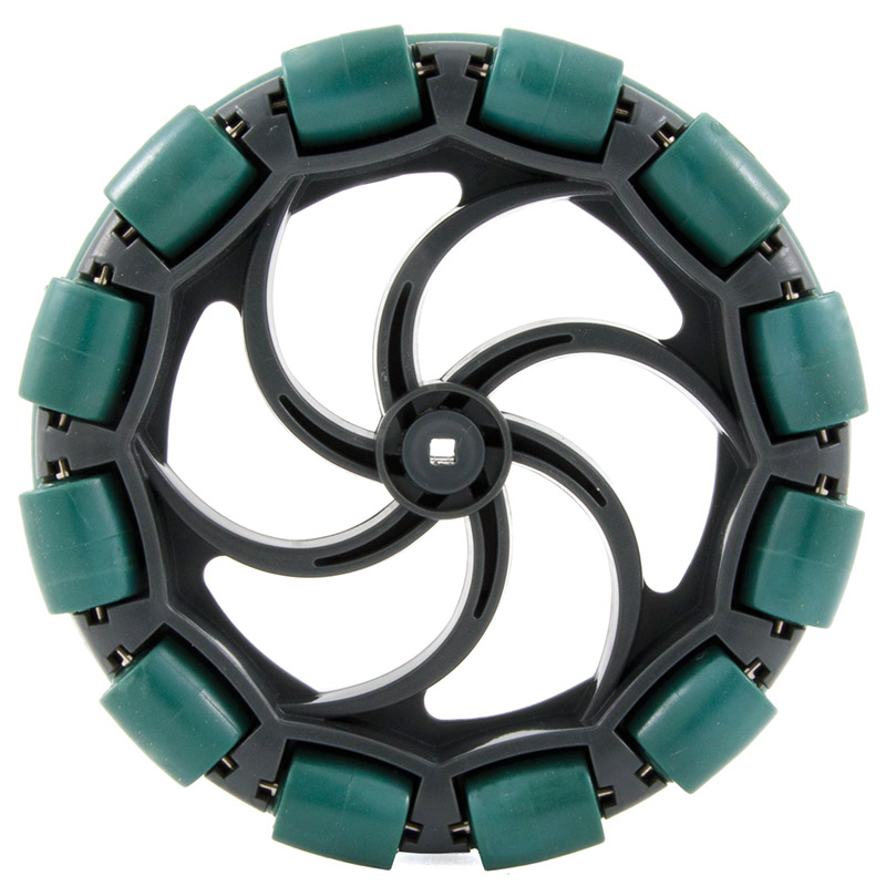
VEX omnidirectional wheel.
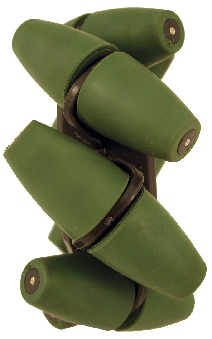
VEX mecanum wheel (side view).
Mecanum Wheels
How It Works
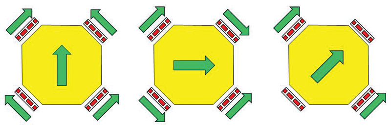
Mecanum wheels are very unique looking. Each wheel has rollers offset by 45 degrees from the wheel and the drive train. This causes the motors to introduce force at 45 degree angles. Different combinations of force vectors can combine/cancel to produce movement in all directions.
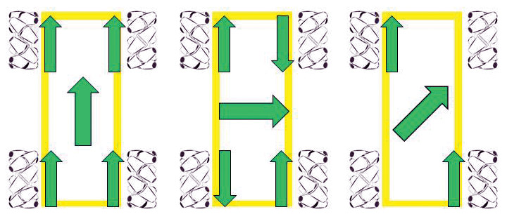
This means that running all wheels in the same direction will result in a forward or backwards direction; running one side in the opposite direction of the other will result in rotation; and running the wheels on one diagonal in the opposite direction of the other diagonal will result in sideways movement.
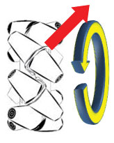
Rotation of a single mecanum wheel provides a "force vector" perpendicular to the rollers. This is the direction that the wheel would want to move.
When putting on mecanum wheels, the rollers of the wheel should create an X when viewed from the top. Meanwhile, on the bottom the rollers should create a diamond. This is an important rule to follow or else the behavior of the robot will not act as expected.
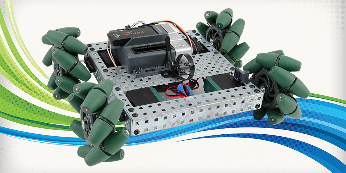
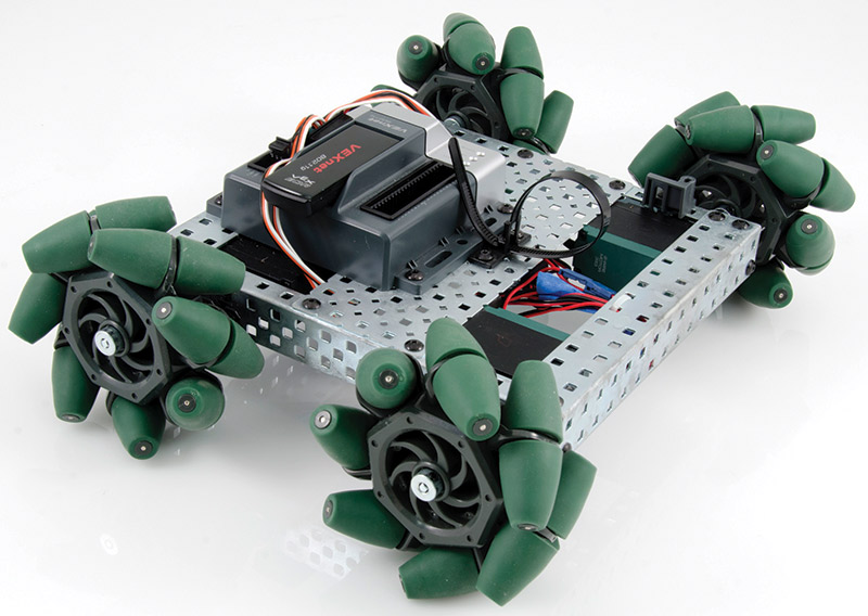
Mecanum wheels are mounted on a 4WD robot as shown. Note the orientation of the rollers. Two of the wheels are mounted with the rollers at +45 degrees and two with rollers oriented
at -45 degrees.
Another important item to consider when using a mecanum drive system is weight distribution and build quality. The mecanum works on the principle of combining and canceling vectors. If the motors cannot match each other, the motion of the robot will not be as expected.
Source Code
The source code to control the robot is amazingly simple. The complete program is barely 20 lines of code. Since joysticks do not always return exactly to the center value of zero, a small dead zone is used to treat all values close to zero as zero.
The actual power applied to each of the four motors is a simple formula of the three joystick axes.
The software was written in ROBOTC — a dialect of the popular C programming language optimized for use with robots.
If you’re building your own robot, you may find that one or more motors move in the opposite direction than intended. You can change this by reversing the two wires to the motor. Or, with ROBOTC, there’s a command (not shown) to have software implement a motor direction reversal:
task main()
{
int Y1, X1; // Vertical, Horizontal Joystick Values
int rotation; // Rotation Joystick Values
int deadband = 20; // Threshold value for deadzone
while (true)
{
// Get value of three joysticks used for speed and
// direction.
// Other platforms may have different code for this.
Y1 = vexRT[Ch3]; // Vertical axis
X1 = vexRT[Ch4]; // Horizontal axis
rotation = vexRT[Ch1]; // Rotation axis
// Implement dead zones to compensate for joystick values
// not always returning to zero
if (abs(Y1) < deadband)
Y1 = 0;
if (abs(X1) < deadband)
X1 = 0;
if (abs(rotation) < deadband)
rotation = 0;
// Convert joystick values to motor speeds
motor[frontRight] = Y1 - X1 - rotation;
motor[backRight] = Y1 + X1 - rotation;
motor[frontLeft] = Y1 + X1 + rotation;
motor[backLeft] = Y1 - X1 + rotation;
}
}
A couple of notes on the code. In ROBOTC, the joystick axes have a range of -127 to +127; other products may provide a range of 0 to 255 or 0 to 1023. In ROBOTC, motor power levels also range from -127 to +127; other systems may use a different scale. If you’re building for a different platform, you may have to adjust accordingly for these factors.
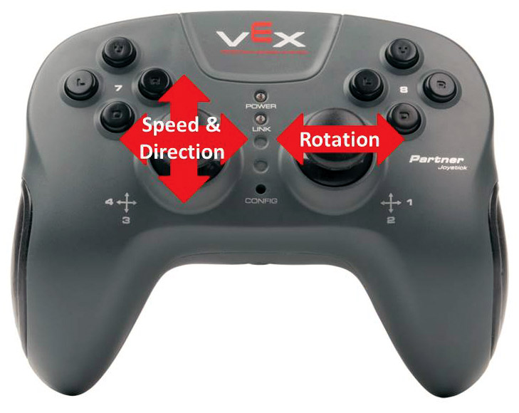
User Interface
A remote control was used to drive the robot using an “arcade style” control. With arcade style control, the horizontal and vertical axes of a joystick specify the speed and direction of the robot. The horizontal axis of a second joystick controls the rotation of the robot.
Omniwheels
How It Works
Omniwheels have small rollers around their circumference that are perpendicular to the rolling direction. The result is a wheel that can roll like a normal wheel but also slide laterally very easily. Therefore, the wheels cannot be mounted in the same manner as the aforementioned mecanum wheel.
The simplest design to understand is a robot with a square base with the wheels situated in the middle of each side. However, while simple, if a force were to be directly applied to one of the corners of the square, two of the wheels would be lifted up. Also, I don’t want to damage my walls by banging a pointy corner of a robot into them. Finally, squares are rather dull. Don’t be a square.
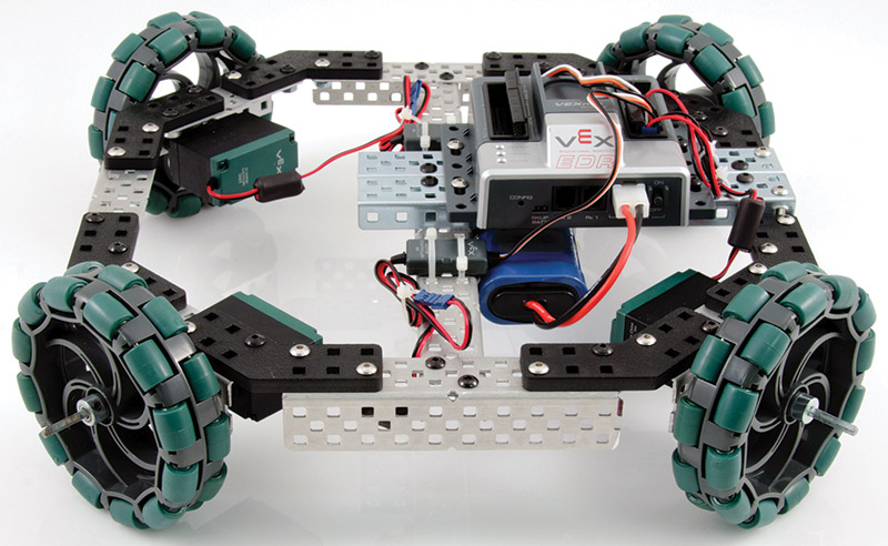
With the square design off the drawing table, I tinkered with the idea of lopping off the corners of the square to create an octagon. I liked it. It solved the weight distribution and pointy corners issue. Also, an octagon isn’t as dull. The octagon shape has a significant advantage in powering the robot. If there’s a wheel on each side, going forward only has two motors powered. With the motors at each corner, going forward uses all four motors.
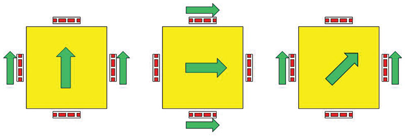
Notice that this runs on the same idea as a mecanum wheel. The wheels are situated at 45 degree angles and create a similar system of combining /canceling force vectors. In smaller robots, the difference between omniwheels and mecanum wheels is miniscule. In larger applications, however, there are different places of stress on the drive system.
The Interface
Omniwheel robots can use the same joystick control as the one for mecanum wheels. The same software also works with omniwheels.
Construction
VEX Robotics Design System — Metalwork
It was a simple job to fabricate both types of robots using parts from the VEX Robotics Design System. This is due to the simplicity and customization that the system offers. It was quite easy to assemble the square base with the numerous available building parts. Standard size parts were used.
The omniwheel robot was not so simple. It required 45 degree angles and custom length beams. The system is designed for cutting beams to a smaller size. However, using the standard steel parts, this can take some time with a hacksaw.
Fortunately, many of the VEX parts are also available in aluminum which is a lot easier to cut. Aluminum was used for the omniwheel robot.
You’d have to trim and bend the stock parts to create the 45 degree angles required for the omniwheel robot. It was more fun to design custom ABS plastic connectors instead; once designed, they were easily cut on a laser cutter. They’re the black plastic parts in the photo.
Once built, the frame is very rigid and almost indestructible. The drawback is that it requires lots of nuts and bolts which are time-consuming to tighten, and often seem to be in cramped corners where it’s difficult to manipulate the tightening wrenches.
VEX IQ
A second omniwheel robot was also built using the recently released VEX IQ system. This system is similar to the VEX Robotics Design System except in plastic. This system comes with a selection of 30, 45, 60, and 90 degree connectors. The octagonal base was easily constructed from stock parts.
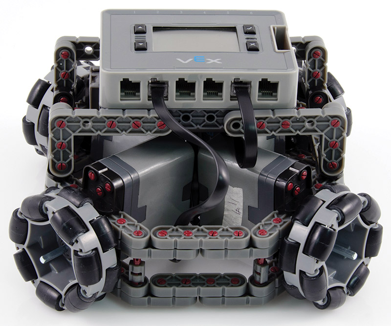
The construction process was much faster. There are no nuts and bolts; the plastic beams are quickly joined together with plastic pins that snap into both beams.
The wiring was also simpler. Motors connect to the brain with cables containing a modified style of the jacks used with telephones. The rechargeable battery slides into the base of the brain.
The VEX IQ motors are really neat. They have integrated high resolution encoders (960 counts per wheel revolution). An embedded CPU in the motor is used to provide precise speed and position control of the motor. This CPU uses feedback from the motor to precisely regulate the motor’s speed. Our simple application here didn’t need this functionality, but it will be used in an upcoming article covering dead-reckoning navigation.
What’s Next
These projects were very simple and easy to learn. The VEX Robotics Design System is a great system for strong, durable robots and the ROBOTC integrated development environment makes this platform viable for just about all your robotic ideas. The VEX IQ system is another very easy and flexible system that gets rid of the somewhat tedious nuts and bolts construction.
This article gives just a basic test for omnidirectional drive systems. There are more advanced ways to control an omnidirectional-based robot. For instance, there are videos of mecanum robots moving in a direction while spinning. While how to do this is beyond the scope of this article, it makes a good exercise if you feel like challenging yourself.
Another challenge could be trying to implement dead reckoning — especially with the integrated wheel encoders in the VEX IQ system.
All the robots constructed here used four wheel drive. The same principles could be used to construct a robot with three wheels. The motors would be positioned at the corners of an equilateral triangle. The control algorithm could be quite complicated as it will involve trig functions which can be messy on some microcontrollers. SV
Article Comments