The Multi-Rotor Hobbyist — Understanding and Balancing Propellers
By John Leeman View In Digital Edition
If you’ve ventured into a hobby shop looking for propellers for your multi-rotor, you’ve probably been overwhelmed by the selection available. There are propellers of different lengths, pitches, and materials — all of which could fit your motor. The price difference between seemingly similar propellers can be large. In this article, we will go over what you need to know about propellers and how to balance them to have the best flight experience.
Propeller Basics
The wall of propellers at any hobby shop is an interesting place. There are lots of packages with specifications that mean little to many new to the hobby. Choosing the right propeller for your multi-rotor can make the difference between a stable, maneuverable, and fun-to-fly machine and a one that barely leaves the ground in a buffeting fit of noise.
Propellers, roughly as we know them, have been around since the Archimedes’ screw. Later, the Wright brothers realized that their airfoil research could be applied to make more efficient propellers that used a twisted wing design. As it turns out, their design was only around 5% less efficient than modern aircraft propellers (http://web.archive.org/web/20110604093014/http://www.memagazine.org/supparch/flight03/propwr/propwr.html)! The main characteristics of a propeller are its length, pitch, bore, direction, and material.
Length
Length is the most self-explanatory of the propeller characteristics. It is simply the length of the propeller from tip-to-tip, generally specified in inches (Figure 1).
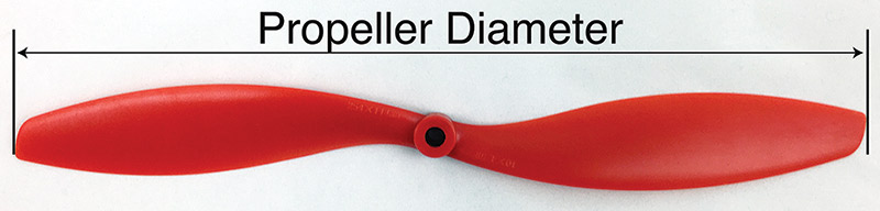
FIGURE 1. The length specification of a propeller indicates the diameter. Props are commonly sold using imperial measurement, but many manufacturers are now marking them with metric dimensions as well.
When propellers are sold, they are commonly marked as a set of two numbers; “10x4.5” for example. The first number (10 in this case) is the propeller diameter. The thrust of a propeller is proportional to the area of the propeller in contact with the air (and a large number of other factors).
If we look back at some geometry, we know that the area of a circle is calculated as pr2 where r is the radius of the circle. This means that increasing the length slightly produces a change in the area of contact that is faster than simple linear growth. We can see this by looking at the graph in Figure 2. Larger propellers need to be spun slower than smaller propellers to generate the same amount of thrust, and are generally more efficient.
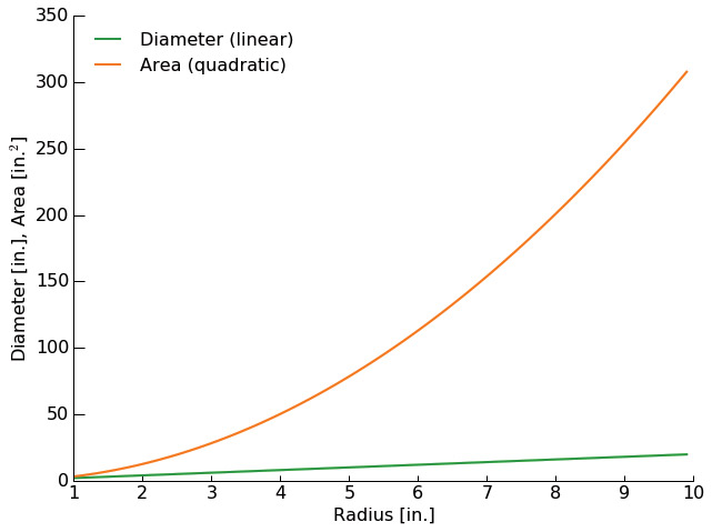
FIGURE 2. The diameter of a propeller grows linearly with the radius, but the area covered by the swing of the propeller grows with the square of the radius. A small increase in propeller diameter can make a big difference in your performance.
With the quadratic growth of contact area with propeller length, you might think we should put 16” props on all of our quads, but, as always with engineering, there is a tradeoff. The larger propellers are also heavier than their smaller counterparts. Anytime you start talking about swinging masses around, the concept of inertia should come to mind. The larger propellers with their greater mass will take longer to change speeds than smaller propellers. If they take too long to change speed, the flight control system will have a very difficult time, and you could end up with a poorly controlled and sluggish quad. I think that for many hobby-sized multi-rotors, this is not a huge concern, but could certainly become an issue at the larger end.
Pitch
The pitch of the propeller is a more complex concept. Pitch is the second number in the propeller specification; 4.5” in our example. The larger the pitch, the more “aggressive” the propeller is and the more steeply the blades will be inclined to the plane of the propeller.
Imagine that we had a way to slowly rotate the propeller into a block of soft foam. The propeller would screw into the foam much like a screw would into a piece of wood. If we traced out the path of the propeller in 3D, we would see a helical path that looks very similar to a screw thread. Suppose we made a mark at the tip of a blade when the propeller was vertical, then rotated it one complete turn and marked the position of that same blade tip. We would have two marks at the same angular position, but offset in the direction of motion by some amount. That amount is the pitch of the propeller — how far it would move in a solid media in one complete revolution (Figure 3). For model airplanes, people often use the mental model of how far the airplane is screwed through the air for each turn of the propeller, though this breaks down somewhat as the air is not a solid media but a compressible gas.
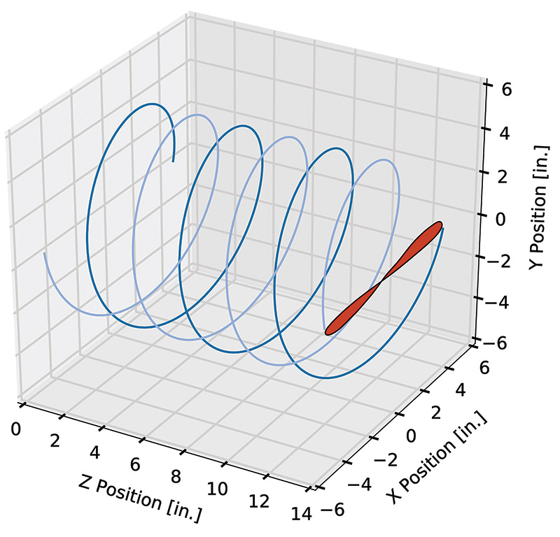
FIGURE 3. Following the tips of a propeller through three complete revolutions, we can see the spacing between each spiral is equal to the pitch of the propeller.
You might wonder why we don’t specify the pitch of a propeller in terms of degrees. Take a propeller and literally or mentally attach a pen to the tip of one blade and to the middle of the same blade. Rotate the propeller though a full turn. You’ll see that the outside pen travelled a much greater distance than the inner pen. For a rotating solid body, we know that every point on the propeller will have the same angular speed (the center and tip both go through 360° in the same amount of time). The tangential speed of the propeller must vary with distance from the center of the propeller because the tip at radius r2 has much farther to travel than the middle of the propeller at r1 (Figure 4).
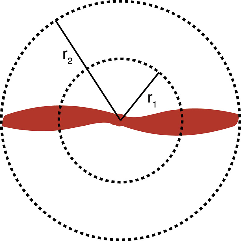
FIGURE 4. At two different radii, the same solid propeller has to travel much different distances. The circumference of the circles traced is linearly proportional to the radius of the propeller at that point.
If we do the math, we can plot the tangential velocity of the propeller along its length (Figure 5).
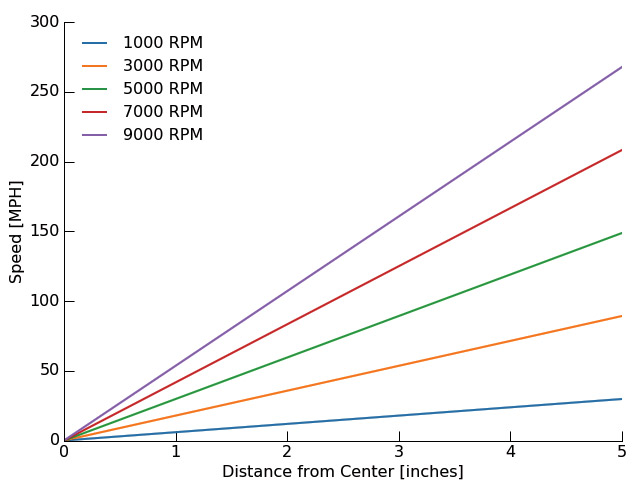
FIGURE 5. The tangential velocity of the propeller must linearly increase with the distance from the center. At the tip of a 10” diameter propeller, the speed can approach 300 MPH! At these speeds, inertia can be a real concern and make the propellers very dangerous.
A consequence of this is that the angle of the propeller blades must change along the length of the propeller to have a roughly constant thrust along its length. Look at your propellers closely and you’ll see the angle becomes much more shallow towards the tip (Figure 6).
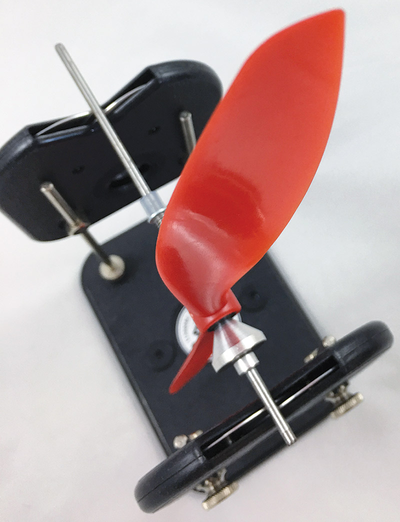
FIGURE 6. Notice how the angle of the propeller changes slightly from the interior to the tip. The angle must be reduced at the tip for the propeller to maintain a fixed pitch, and is called “washout” in the aviation community.
There are further complications as well that are beyond the scope of what we want to do here. Some of the other features you’ll observe on the propellers are designed to direct their thrust towards the center so that the thrust is concentrated just behind the propeller instead of in a flat sheet. This is effectively like ducting the propeller!
Let’s consider two propellers: a 6x3 and 6x4.5. The propellers are both 6” in diameter, but have a pitch difference of 1.5”. The propeller with the smaller pitch will be easier to spin through the air and will require less current flowing to the motor to maintain a given speed. It will also produce less turbulence and utilize the torque peak operating range of your motor. For multi-rotors that are designed to be aerial video platforms, we generally use lower pitch propellers. For multi-rotors that need high speed capability — like racing quads — higher pitch propellers are often used.
Bore
The bore of the propeller describes the diameter of the hole used to mount it to the motor (Figure 7).
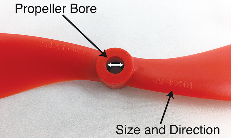
FIGURE 7. The bore of the propeller must be matched to the drive motor to avoid any off-center operation. In this photo, the propeller size, pitch, and direction are visible in the casting as well.
Many multi-rotor propellers are cast with a pretty large bore and come with a set of hard rubber bushings to reduce that bore to the common motor shaft diameters (Figure 8).
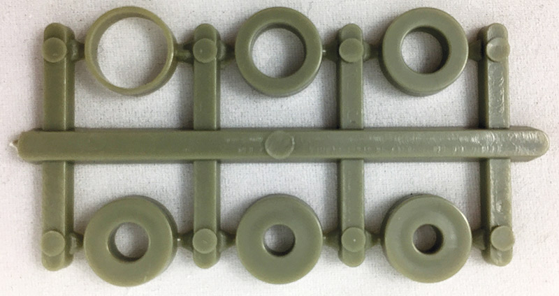
FIGURE 8. Bushings are often included with model aircraft propellers to make the same propeller fit a variety of motors and vehicles. Be sure you pick the bushing that snugly fits your motor’s output shaft.
Never use a propeller with an incorrectly sized bore. The chances of being able to mount it so that it is centered on the axis of rotation are virtually non-existent. That means the system will be wildly out of balance. Vibration will likely cause the prop to move until one wall of the bore is touching the motor shaft. By this point, your airframe will be vibrating violently and there will likely be damage to it and possibly to you. It is also unwise to drill out a propeller bore without proper machining equipment for the same reason.
Direction
Propellers are sold in clockwise (CW) and counter-clockwise (CCW) versions; also referred to as right and left handed propellers. For a quad rotor, you need two of each. The direction of rotation is defined when looking down from above at the top of the propeller. Most manufacturers mark the propellers with a letter on the casting, but you can also look at the direction that the leading edge of the propeller points (Figure 9). Make sure that you have propellers of the correct direction on motors rotating the appropriate direction!
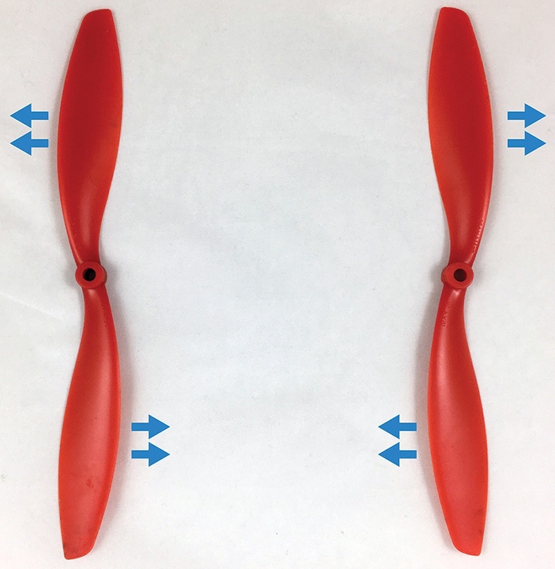
FIGURE 9. By looking at the leading edge of a propeller, you can determine its direction of rotation. The swept nature of the leading edge indicates that the propeller on the left is a left-handed (counter-clockwise) propeller, while the one on the right is a right-handed (clockwise) propeller.
If your quad will not lift off, but rather tries to flip over in one direction or vibrates with no life, it is very likely that the propeller and/or motor direction configuration is incorrect.
Material
Model aircraft propellers are commonly made out of wood, plastic, or carbon fiber. Wooden propellers are common on model airplanes, but I haven’t seen them used on multi-rotors. Wood is a pretty heavy material, so it adds weight to the vehicle and is much harder to speed up or slow down compared to a similarly sized plastic or carbon fiber propeller.
Plastic propellers are the most common, and what we’ve used on our home-built quadcopter and also the Parallax ELEV-8. Plastic propellers are lightweight, economical to manufacture and buy, and easy to balance. I’ve flown plastic props on most everything I’ve owned — airplanes and quads alike. In a crash, you can almost bet on the brittle plastic failing and needing a new propeller. The bending and fracture of the propeller does absorb some of the energy of impact though, so it can save your motor sometimes.
Carbon fiber propellers are very expensive compared to their plastic counterparts, but some pilots are devoted fans. Carbon fiber is phenomenally light meaning that larger propellers can still have quick spin up/down times. The propellers are also outstandingly strong which is good in most cases, but also means that more force can be transferred to the motor and airframe during a crash. They are also much more damaging if they encounter objects while in flight. Remember the video of a carbon-fiber propeller interacting with a human simulant?
Why Balance Propellers?
Have you ever noticed that while driving your car, there was a vibration in the steering or that you could feel through the seat? The intensity (amplitude) of the vibration may even have changed with different speeds. If you took the car into the shop, the mechanic likely balanced the tires for you. The fact that the center of mass of the tire and wheel was off center was creating a problem that can be annoying at best and quite dangerous in extreme cases. The wheel was balanced by using a machine to characterize the center of mass, then by clamping small weights onto the outer rim to move the center of mass (Figure 10).
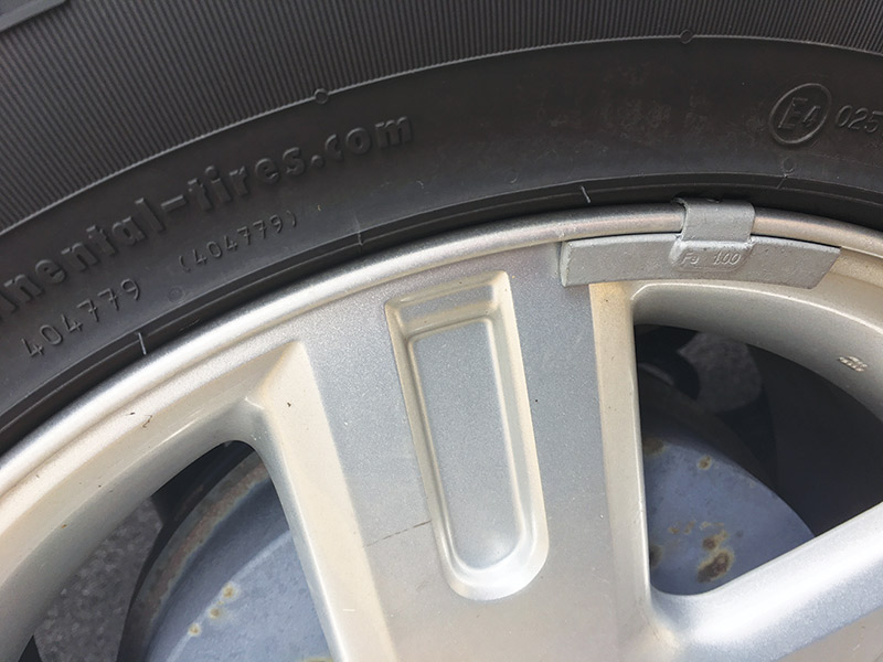
FIGURE 10. Weights such as these are clamped onto your car’s wheels to balance the wheel/tire assembly. We do the same thing with our model propellers, but with much smaller masses.
Have a look next time you go for a drive; the weights may be on the back side of the wheel to be hidden for aesthetic purposes. Turns out that our multi-rotor propellers spin at several thousand RPM and need to be balanced as well.
Once you have selected the best propellers for your multi-rotor, you are likely to rush home, bolt them onto your motors, and go for a test flight. You’ll notice that the motors are vibrating some and that the vehicle makes a lot of noise. This is because the propellers need to be balanced! Generally, the more expensive propellers are much better out of the package and may be fine to fly, but balancing is a very simple procedure and one I would recommend for any propeller you buy. Don’t forget to pre-balance your spare propellers for your field kit as well!
Propellers are generally injection molded bits of plastic (though there are wood, carbon fiber, etc.). As with any manufacturing process, there is some variance in the final product. For an ideally balanced propeller, the center of mass is precisely in the center of the bore — directly in line with the axis of rotation. Any movement of the center of mass from that axis means that the center of mass is orbiting the axis of rotation and producing vibrations. At low speeds, some imbalance is not a problem, but our propellers spin very fast and unbalanced propellers can spell trouble.
This trouble can come in the forms of noisy flight and excessive vibration. In addition to being annoying, the vibration can loosen fasteners that are holding the motors to the frame and holding the frame together. It can also ruin what could have been beautiful aerial video by introducing a rolling look to the picture that is the high frequency vibration aliased into the low frame rate recording via the camera capture pattern (often a “rolling shutter”). The vibration is also repeatedly flexing parts of the airframe. If the flexure is large enough and occurs for long enough, the materials used in the airframe can fatigue and fail. Metal fatigue has been the cause of several real aircraft disasters, including a series of crashes of the de Havilland Comet airliner (which turned out to be a story about square windows and stress concentrations).
Fatigue as a failure mechanism was even written about in the fictional book No Highway by Nevil Shute in 1948. You can demonstrate fatigue by bending a paper clip back and forth repeatedly; eventually, the metal will snap! Not something you want to happen to your airframe in flight.
Dynamic Balancing
Dynamic balancing is a really nice way to balance the entire rotating assembly: motor, propeller, and prop nut. It results in very smooth flight and low vibration, but it is also pretty complicated. To dynamically balance a system, we need to run the system through a range of rotation rates while monitoring the vibration via an accelerometer and the position of the system via a rotary encoder or other position transducer. This is indeed how car wheels are balanced. It’s worth looking at some videos on YouTube of how it works. Dynamic balancing can take care of those “I only feel the vibration at 65-75 MPH” problems.
Dynamic balancing can be a great benefit to model aircraft balancing, but it is also a complex technique that most hobbyists do not pursue. There are some trying to make a full dynamic balancer; others are using a cell phone as the accelerometer or attaching a laser pointer to the motor mounting arm and experimentally balancing the system to produce the smallest amount of wobble. At some point in the future, we may explore dynamic balancing, but the next technique is cheap, easily performed, and often does a good enough job even for videography.
Static Balancing
Static balancing involves removing the propeller from the system and putting it into a balancing frame. This frame holds the propeller, centered around an axle that is suspended on very low-friction bearings. Often, knife edge rollers or magnetic bearings are used. If one side of the propeller is heavier than the other, the heavy blade will settle at the bottom of the assembly. By iterating — either adding weight or removing weight from the light or heavy blades, respectively — the propeller can be balanced surprisingly well.
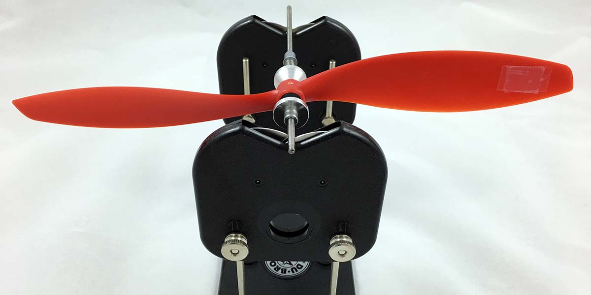
The static balancing method is much simpler than dynamic balancing, and is also much less dangerous as it does not involve spinning the propeller at high speeds on the bench top. The equipment to do this is also very economical. While I’ve heard of people balancing an axle between two coffee mugs, I would recommend buying a commercially produced balancer. For about $25, you can purchase the Du-Bro 499 Tru-Spin balancer (Figure 11). I’ve used this to balance several sets of multi-rotor propellers and haven’t had any problems.
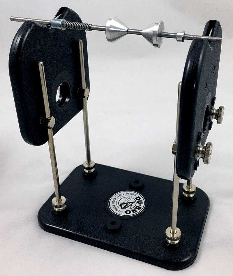
FIGURE 11. The Du-Bro Tru-Spin prop balancer is a relatively inexpensive and reliable way to balance your propellers.
Static Balancing Procedure
To static balance your propellers, you should mount the propeller on the axle that comes with your balancing kit (Figure 12).
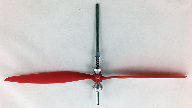
FIGURE 12. Propellers are clamped and centered on the axle by two aluminum cones. The moveable cone is held firmly against the propeller bore by a spring that is held in compression by a tight fitting piece of rubber tubing.
You can experiment with balancing the propeller with and without the bore-reducing bushing inserted. However, I have not noticed a large difference in my experimentation. Make sure that the balancing apparatus is level on your bench (Figure 13) and that the air in the workspace is still.
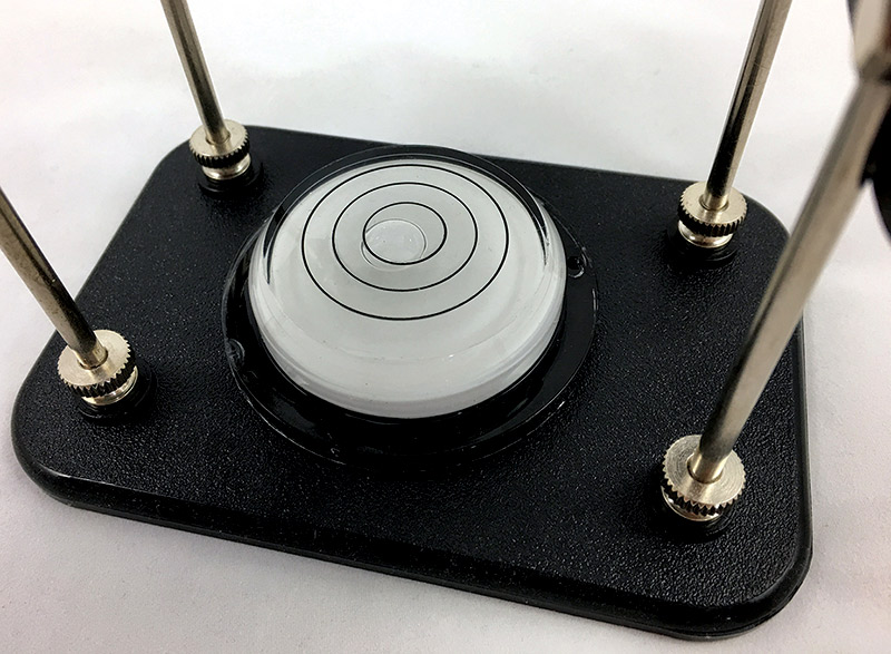
FIGURE 13. A simple bubble level can be used to make sure your propeller balancer is leveled on the workbench. These are available at the hardware store for about $3 and are always handy to keep on hand.
A light breeze blowing through the shop is nice, but will provide unending headaches when balancing propellers. Place the axle with the propeller on the balancing stand and wait for it to settle. It is very likely that one blade will settle to the bottom of the stand (Figure 14).
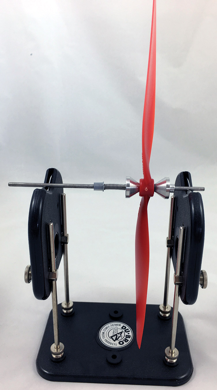
FIGURE 14. Most propellers will very quickly settle with one blade hanging down. This is the heavy blade. We can add weight to the light blade, or carefully sand weight off the heavy blade to balance the propeller.
To balance the propeller, we’ve got two options. We can add weight to the light side that is sticking up or we can subtract weight from the heavy side that sinks to the bottom.
If you want to add weight to the light side (arguably the easier way to balance a propeller), you can place a small amount of gel-type Super Glue™ in a thin layer on the underside of the light blade at the tip (Figure 15).
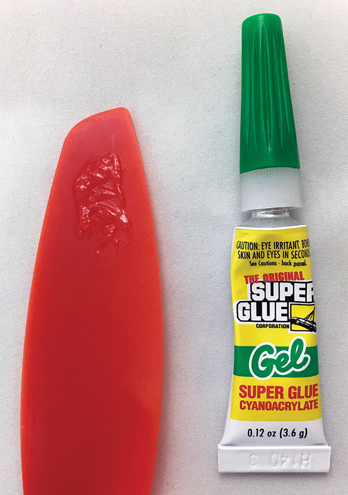
FIGURE 15. Weight can be added to the propeller by applying a thin layer of gel-type Super Glue, and either waiting for it to dry or by using an accelerator to instantly cure the glue.
Using an accelerator spray to instantly cure the glue is advisable. An even quicker solution is to place a small bit of cellophane tape on the underside of the propeller (Figure 16). The tape can be trimmed and easily removed, making it a good choice for beginners.
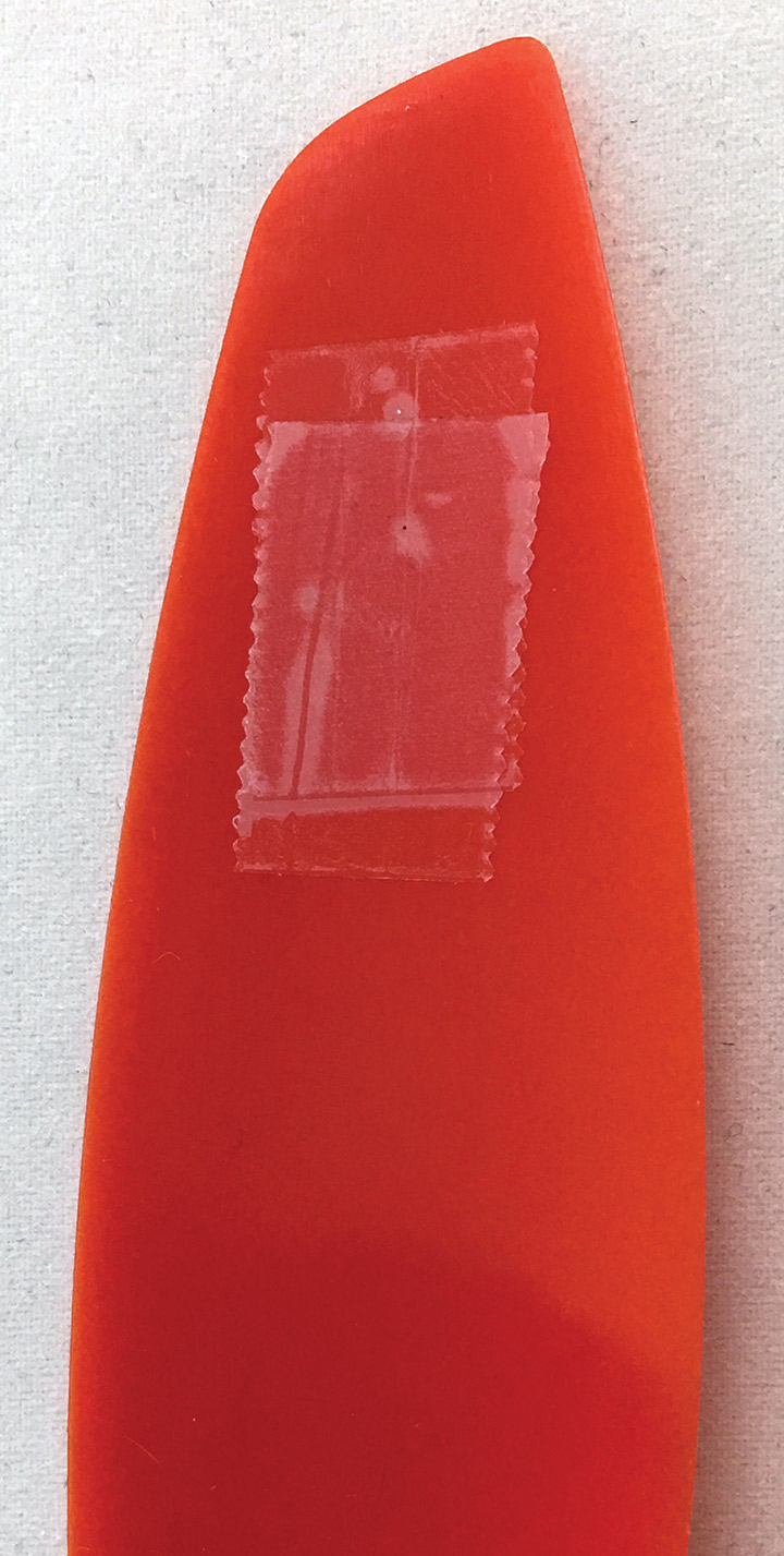
FIGURE 16. Adding bits of cellophane tape is another way to add weight to the light blade. This is the quickest way to balance propellers, but is not as permanent of a solution.
If you’d like to remove weight from one side of the propeller, you can use a fine grit sandpaper; 220 works well. Sand off a small amount of material from the heavy blade (usually from the underside). Try to evenly remove material so that the propeller does not become imbalanced from the tip to the tail of the blade (Figure 17).
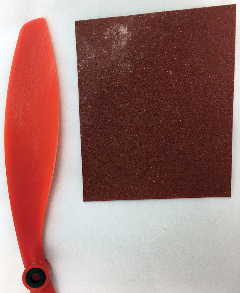
FIGURE 17. Some 220 grit sandpaper can make quick work of removing mass from the heavy blade. Be sure to sand evenly at the end of the propeller and check the balance often.
If you use this technique, be sure to re-check the balance often because if you remove too much, you will either need to sand the opposite blade — removing more material than necessary — or add mass back into the blade you over-sanded. The removal method does have the advantage that there is no glue or tape to accidentally abrade away or come off and unbalance things again.
After adjusting the mass of the blade, put the propeller back on the stand and see how you did. Maybe you’ll need to remove more mass, add more tape, or otherwise play with the balance. After a few tries, the propeller should be getting close to balanced.
When balanced, it will sit in any position at which you place it, without any blade always falling to the bottom (Figure 18). With practice, you’ll be able to balance a propeller in a few minutes. I can balance a set for my quad in less than half an hour, and that is time very well spent.
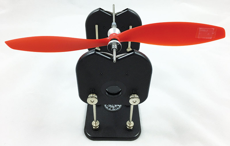
FIGURE 18. A well-balanced propeller will maintain any orientation it is left in. You will notice a marked difference in the amount of vibration and noise your quad makes during flight after balancing.
Closing Thoughts
Don’t be afraid to pick up several sets of different propellers next time you are at the hobby store or ordering something from Amazon.
Experimenting with them could lead to performance gains on your multi-rotor for your particular application. SV
Article Comments