Versatile Stepper Control
By William Cooke View In Digital Edition
Stepper motors are a staple of robotics. They’re great for precise speed and positioning. It’s also easy to control one. But what about two, or three? With different step rates? For different amounts of time? While your microcontroller continues doing other tasks? It can quickly become difficult, but with the technique presented here you can do all that and use only about two or three percent of the microcontroller’s time.
I’m going to borrow a method often used for generating radio and audio signals and use it to generate step rates for motors. We’ll be able to step several motors, with each motor having individual control of the step rate and number of steps.
The code uses interrupts and runs mostly in the background, allowing your controller to continue doing whatever else it needs while the steppers continue stepping along. The example uses an Arduino, but you can apply it to almost any controller.
Brief Review of Steppers
Let’s take a brief review of how to control a stepper. We’ll only cover the parts relevant to us, so if you want to know more about steppers, check out the References.
For control purposes, there are two basic types of steppers: bipolar and unipolar. Refer to Figure 1.
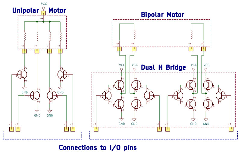
Figure 1. Schematic diagram of unipolar and bipolar stepper motors with representative driver circuits. The circuits are incomplete and only used for reference.
A unipolar motor appears to the control circuits as (usually) four motor windings.
Those four windings are connected together at one end, either internally or externally to the motor. That mutual connection is attached to one side of the power supply, most often the positive side. By connecting the other end of the winding to the other side of the supply, our circuit can energize that winding. We only control one side of the supply. Hence, the name “unipolar.”
A bipolar motor, however, usually has two windings. We control both ends of both windings. Our control circuit (using an H-bridge or something similar) can connect either end to either side of the power supply.
If we connect one end to positive and the other to ground, current will flow in one direction. If we reverse both ends, current flows in the other direction. If both ends are connected to the same side of the supply, no current flows. So, now we can energize the winding in either direction or not at all. That’s why these are called “bipolar.”
It would seem the control of these two types of motors would be very different. However, it turns out our software can control them exactly the same. Both types have four connections. The unipolar has connections to one end of four windings. The bipolar has connections to two ends of two windings. In both cases, if we energize the windings in the correct sequence, the motor will step.
A single output bit can either energize or not energize a winding in a unipolar motor. In a bipolar motor, two bits together determine if a winding is energized and in which direction. A sequence of patterns applied to either motor makes it go around. Reversing the sequence makes it spin the other direction. It turns out that both motors use the same patterns and sequences.
There are three common sequences of patterns: full-wave, half-wave, and half-step. The full-wave and half-wave take a complete step with each pattern change. The half-step takes half a step (as expected) for a total of twice as many steps. Look at Figure 2 for all three patterns and how they apply to both types of motors.
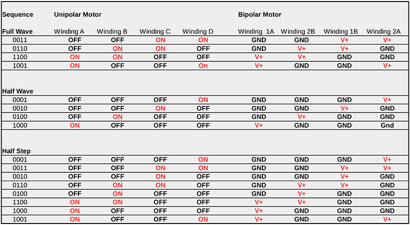
Figure 2. Full-wave, half-wave, and half-step stepping patterns for unipolar and bipolar motors. The table entries for the windings match those in Figure 1.
The full-wave sequence energizes two windings at once and gives the most torque. It also uses the most energy.
The half-wave sequence only energizes one winding at a time. Although it also takes full steps, the steps are halfway between those of the full-wave sequence. Since only one winding is energized, it has less torque but uses less power.
The half-step sequence is a combination of the two previous sequences. It takes twice as many patterns but gives twice as many steps. It also gives torque between the other two. The driver electronics may be as simple as four transistors for a unipolar motor. H-Bridge chips are typically used for bipolar motors, but a DPDT relay is also effective.
In the example system shown, I used a ULN2803A (with eight Darlington pair transistors) for two unipolar motors and a SN754410 dual H-bridge to control one bipolar motor.
To control the motor, we send the bit pattern to the winding drive electronics. Stepping through the table of bit patterns — either forward or backward — steps the motor forward or backward, respectively. When we reach one end of the table, we wrap around to the other and continue on.
Controlling One Motor
Once we decide to use a stepper, we may want to step some number of steps per second for a certain number of steps. After a bit of thinking, we dive in and write some Arduino code. Maybe it looks like this:
uint8_t fullWaveTable[] =
{ 0x03, 0x06, 0xc0, 0x09 }; // Full Wave table 0011, 0110, 1100, 1001
void stepMotor(uint16_t steps, uint8_t delayTime)
{
for(uint16_t step = 0; step < steps; step++)
{
uint8_t outputValue = fullWaveTable[step % 4];
sendToMotor(outputValue); // Send this bit pattern to controller
delay(delayTime);
}
}
That will work. It will step a motor up to 65,535 steps with a delay between steps of 0 to 255 milliseconds. Unfortunately, it has problems.
Perhaps the most obvious problem is that the Arduino can’t do anything else while the motor is running. If we ask it to step the motor 10,000 steps with a delay of 20 milliseconds (50 steps per second), our Arduino will be tied up doing nothing else for 10,000 * 20 = 200,000 milliseconds. Over three minutes.
A bit less obvious is what if we want a step rate of 750 steps per second? A delay value of 1 gives about 1,000 steps per second and a value of 2 gives 500 steps per second. We could use something like delayMicroseconds() and that might fix the timing problem, but it doesn’t help with the other issues. Plus, it adds plenty of problems of its own. We won’t pursue that any further.
Here’s another problem. Suddenly, we remember the robotic arm we’re building needs three motors moving simultaneously but at different rates, and may not start and stop at the same time.
I encourage you to try to extend the function above to handle two motors with different numbers of steps and different stepping rates. If you manage to make two work, try three.
A Better Way
We can take a big step forward by using interrupts. An interrupt is like a phone ringing. You can be working on something and paying no attention to your phone, but when it rings, you stop what you’re doing and handle the call. When complete, you start back right where you left off.
An interrupt in a microprocessor is like a telephone ring. The processor pays no attention to some device until an interrupt is activated; it stops what it’s doing and saves enough information to come back later. It does whatever is needed by the interrupt and goes back to what it was working on.
If we have some device interrupt the processor at regular intervals, we can handle the stepper motor(s) without using any delays. Instead of spinning our wheels waiting on time to pass, we do other tasks that need to be done.
For example, if we have a hardware timer interrupt the processor 1,000 times per second, we can step our motor each time. If we want it to step slower, we can step every second or third or whatever time. That solves the problem of the controller spending all its time waiting. It also makes it fairly simple to control more than one motor. We still have the issue of resolution; we can have 1,000 steps per second or 500 steps per second, but not 750 or 800.
Interrupts are a huge topic by themselves. It’s important to keep the Interrupt Service Routine (ISR) short and fast. It’s also important to protect any data that may be accessed by both the interrupt and the main code.
Often, that means turning off interrupts in the main code before accessing that data and turning them back on after. You can see examples in the project we’ll be discussing, plus Reference 2 has some good basic information.
Fractional Steps
What if we could take an arbitrary fraction of a step? Say, 4/5 (0.8) or 3/4 (0.75)? With 1,000 interrupts per second and taking 4/5 steps per interrupt, we could have 800 steps per second. Or, 3/4 would give us 750 steps per second. It turns out we can.
Radio and audio frequency signal generators, arbitrary waveform generators, “wavetable” sound systems, and various other types of signal generating systems use a technique called Direct Digital Synthesis (DDS). We can borrow DDS to generate our stepper waveforms.
DDS is a fascinating technique and I encourage you to check the References to learn more about it. Let’s apply it to making things spin!
Instead of an audio or radio signal, our waveform is the pattern sequence we chose to drive our stepper. By taking fractional steps at each interrupt, we can get almost any desired step rate up to the maximum, which is the interrupt rate.
The trick is a variable called a “phase accumulator.” The variable is broken into two parts: two or three bits are used to index into our pattern sequence table; the rest represent a fraction.
As an example, let’s create a five-bit phase accumulator and use the full-wave table. For either the full-wave or half-wave tables, we use the most significant two bits, and for the half step table, the upper three bits. Refer to Figure 3.
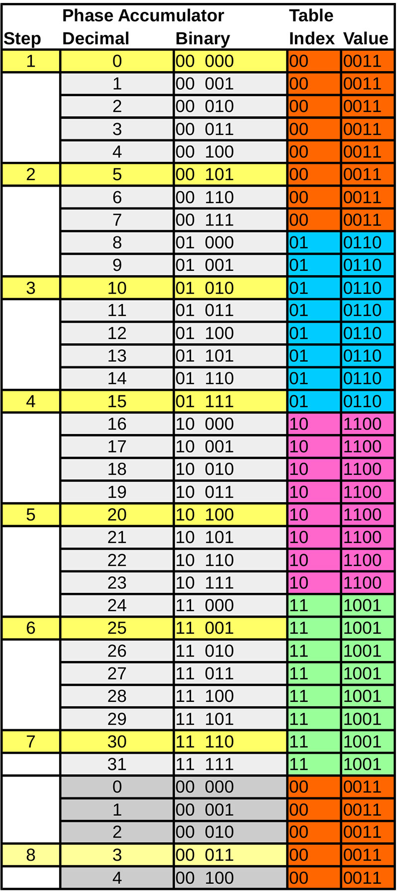
Figure 3. An example five-bit phase accumulator showing how steps are taken with an increment of five. The individual patterns are color-coded on the right and the phase accumulator values are highlighted in yellow.
When our interrupt calls, we add a number to the phase accumulator. Then, we take the most significant two bits to index into the step table. We output the value at that location to the motor controller.
Those extra three bits represent a fraction. Three bits represent eight different numbers from zero to seven, or 1/8 of a step. Adding one to the phase accumulator each time effectively takes 1/8 of a step. If we add four each time, we take a half step (4/8). Adding eight each time will take a full step, which is the max.
In Figure 3, the entries highlighted in yellow represent the steps taken with a five-bit phase accumulator, a four-entry table, and an increment of five.
You can see some numbers are output more than once, but that has no effect on the result. The motor won’t care if you re-write the same value to it.
Increments can be any value from zero (motor stopped) to eight (one step per interrupt.) Our step rate can be 1,000 * n/8: 0, 125, 250, 375, 500, 625, 750, 875, and 1,000. If we increase the size of the phase accumulator, that leaves more bits for the fraction. A good size is 16 bits.
With a four-entry table, 14 bits are left for the fraction, giving a step resolution of 1/(2^14), or 1/16384 (0.000061) step. Again, at 1,000 steps per second, we get 1,000 * n/16384 steps per second.
Here is the general formula:
StepsPerSecond = InterruptRate * Increment / (2^FractionBits)
We rearrange that to be more useful and find the needed increment:
StepRate = InterruptRate * n/16384
rearranging:
n = StepRate * 16384 / InterruptRate
To find n for 750 steps per second:
n = 750 * 16384 / 1000 = 12,288
or for 800:
n = 800 * 16384 / 1000 = 13,107.2.
Round down to 13,107 for 799.99 steps per second — probably close enough. If you really need better resolution, you can go to a 32-bit phase accumulator, but that isn’t often necessary.
What if we want to go really slow?
n = 0.1 * 16,384 / 1,000
n = 1.64 round to 2
StepRate = 1,000 * 2 / 16384 = .122 steps per second
Remember that you can never take a step larger than 1.00 or the motor will miss steps. That means for a 16-bit phase accumulator and two-bit index, the maximum value is 16,384. For a three-bit index, it’s 8,192. In either case, we get one step every interrupt.
Note how simple it is to take a step and calculate the next one:
- Use the upper bits of phase accumulator to index table.
- Output table value to motor driver.
- Add increment to phase accumulator, rolling over at either end.
That’s it! Simple and fast. Note that the increment can be negative, which steps backward.
Example Implementation
I promised an Arduino example. Let’s use an Arduino Nano, two unipolar motors, and one bipolar motor. We will use the half-wave step table. It should be relatively simple to change how many and the types of motors or the step table used if you stay with an Arduino.
Moving to a different controller will be more work; you’ll need to know what timer, interrupt, and input/output resources are available. The schematic is shown in Figure 4.
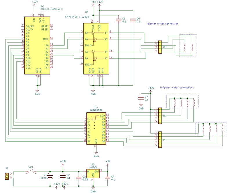
Figure 4. Schematic diagram of the example system showing the Arduino Nano, the ULN2803 used to drive two unipolar motors, and an SN754410 used to drive a single bipolar motor.
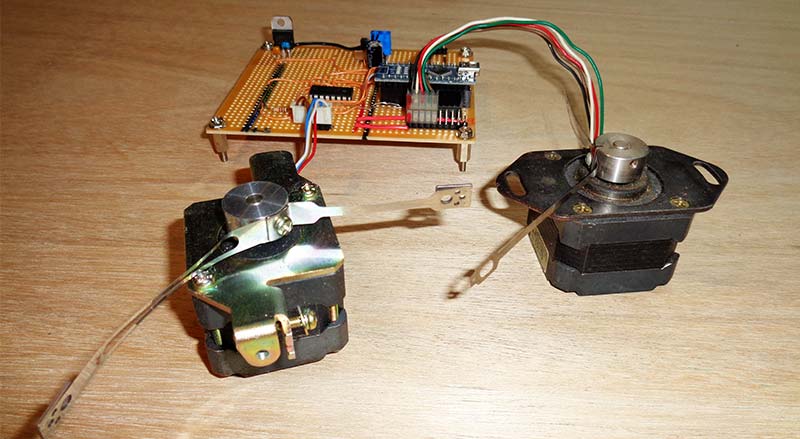
Photo 1. The example prototype board with one unipolar and one bipolar motor attached.
The complete source code (Listing 1) is available in the downloads.
Getting the Interrupts
First, we need a source of interrupts. Most stepper control applications will be well-served with an interrupt rate of around 1,000 interrupts per second. That will allow almost any rate up to the interrupt rate. For a stepper with 200 steps per revolution, we get five revolutions per second or 300 RPM.
The Arduino has a timer that interrupts close to 1,000 times per second for the millis() counter. Timer 0 on the AVR chip (the chipset used by most Arduinos) counts from 0 to 255 and interrupts when it rolls over to zero. Actually, 997 times per second; close enough. The only problem is we can’t hijack that interrupt. But we can hitch a ride!
Timer 0 also has two compare registers not normally used that can interrupt when their value matches the counter. Let’s use one.
To avoid the interference to the millis() interrupt, we set the compare register to a value other than zero. A good choice is 0x20 (32 decimal); about 1/8 millisecond after the rollover interrupt. Plenty of time for the millis() counter to finish. It’s simple to do. We write the value to the compare register, then enable the interrupt. We do that in the setup() function. Here’s the required code:
// Set up the Compare A Register timer interrupt
OCR0A = 0x20; // Set the compare A register to 0x20, away from 0
TIMSK0 |= 2; // enable the compare A interrupt
Processing the Interrupt
When the interrupt occurs, the ISR is called. It looks much like any normal function, but there are some differences. First, a special syntax is used to create it. Second, it must not have any inputs or return a value.
Interrupt routines should be short and fast. They should only do the minimum amount of processing required. Anything that can be done outside the ISR should be. Interrupt programming can be full of headaches, but if you’re careful, it isn’t too bad. I strongly encourage you to read up on the subject.
The ISR is the heart of this method. The demo is for an Arduino, but most of the code is generic and should work unchanged or with small changes on most processors. The code in the listing is heavily commented, so I won’t discuss most of it, but let’s take a look at the ISR.
First, there are several variables that technically aren’t part of the ISR but are critical to its operation. The first — stepper_phase — is an array that holds the phase accumulator for each motor.
The second is another array — stepper_stepSize — that holds the phase increment for each motor. Next is stepper_steps, holding the number of steps for each motor to take. The last is a single variable called stepper_running to indicate if any motors are currently running.
Here’s the first half of the ISR. The part not shown is the output to the motors. You can see it in the main listing, but you’ll likely need to change it to match your hardware.
ISR(TIMER0_COMPA_vect)
{
static uint16_t oldIndex[NUM_MOTORS]; // store old index to test if we step
if(stepper_running)
{
uint16_t index;
uint8_t out[NUM_MOTORS];
for(int mtr = 0; mtr < NUM_MOTORS; mtr++)
{
if(stepper_steps[mtr] != 0)
{
stepper_phase[mtr] += (uint16_t)stepper_stepSize[mtr];
index = stepper_phase[mtr] >> stepper_indexShift;
out[mtr] = stepper_stepTable[index];
if(index != oldIndex[mtr])
{
stepper_steps[mtr]--;
oldIndex[mtr] = index;
}
}
}
// Code to output to motors goes here
}
}
The first line of the ISR is how we declare an ISR for the Arduino compiler. It looks like a function named “ISR” with the name of the interrupt in parentheses. For any Arduino based on the AVR chips, you can get the interrupt name from Reference 4. If you’re using some other type of controller, you’ll need to find out how to use an appropriate interrupt.
You’ll have to research that on your own. Interrupt control is not a standard part of the C or C++ languages, so every compiler does it differently. Even the same compiler may be different on different processors.
Inside the ISR, we first declare an array named oldIndex to hold all the previous index values, so we can determine if a motor stepped in this iteration. By declaring the array as “static,” it holds its values between calls to the ISR. Another array named out temporarily holds the table values to write to the motors.
The main body of the ISR is a for loop that cycles through all the motors. First, it checks if the motors are running and skips everything else if not. If the motors are running, it adds the phase increment for each motor to the corresponding phase accumulator.
The resulting phase is used to find the index and look up the needed pattern from the pattern table, stepper_stepTable. It saves that pattern to use later.
The new output values found for the motors are compared to the previous values held in the oldIndex array. If they’re different, it means that motor took a step, so the step count is updated. The only thing left to do is write the new table values out to the motor controllers.
The ISR is short and simple. All the supporting code and interface functions are in Listing 1.
In the example, I used direct port I/O. I highly recommend doing that. Using the digitalWrite function is slow and can cause performance issues with your code as well as the motors. Reference 6 has information on using direct port I/O.
n all, the example controls three motors and uses only about 2% of the processor’s time, leaving plenty for your other code.
Conclusion
You can take the example project here and use it immediately to control three motors. Of course, much more can be done by using it as a basis for your own ideas.
I hope you’ll take the techniques presented and go further. Interrupts are a powerful tool and most processors have many interrupt sources.
he phase accumulator/DDS method presented here is useful for creating many different types of repetitive actions that don’t match timer interrupt rates. I look forward to hearing what you create and perhaps reading about it in these pages.
As a final note, I’d like to thank my friend, Thomas for asking the question that led to this article, and then encouraging me and reviewing it. SV
References / Further Reading
1. Douglas W. Jones on Stepping Motors
http://homepage.divms.uiowa.edu/~jones/step/
More than you ever wanted to know about steppers.
2. Arduino attachInterrpt() Reference
https://www.arduino.cc/reference/en/language/functions/external-interrupts/attachinterrupt
3. DS Tutorial
https://www.analog.com/en/analog-dialogue/articles/all-about-direct-digital-synthesis.html#Ask
The Application Engineer—33: All About Direct Digital Synthesis by Eva Murphy and Colm, Slattery. A great introduction to Direct Digital Synthesis.
4. Interrupt Names
AVR LIBC Interrupts
https://www.nongnu.org/avr-libc/user-manual/group__avr__interrupts.html
Lists the interrupt names recognized by the GCC compiler for all supported AVR processors.
5. Wikipedia entry on Direct Digital Synthesis
https://en.wikipedia.org/wiki/Direct_digital_synthesis
More good information on DDS.
6. Direct Port I/O on Arduino
https://www.arduino.cc/en/Reference/PortManipulation
Explains how to use direct port I/O instead of the Arduino single pin method.
Article Comments