Using a Servo with the TS-7180 SBC
By Michael Peters View In Digital Edition
Servos are a ubiquitous and versatile part of everyday electronic gadgetry. From unlocking doors to controlling a robot’s movements, nearly anywhere a “computer” needs motion you will probably find a servo. Servo control is an important trick in any embedded systems software engineer’s or robot builder’s repertoire. The TS-7180 SBC (single-board computer) from Technologic Systems (www.embeddedarm.com) makes a conveniently apt servo controller. However, there are some caveats that might surprise the uninitiated.
Assumptions
This article does make some assumptions:
- You already know how to obtain serial console on the SBC.
- You are already familiar with basic Linux usage and the Linux command line.
- You have a TS-7180 running the standard shipping image as provided by Technologic Systems.
Definitions
Actually, there’s a whole lot of different kinds of “servos;” many more than the scope of this article can handle. The word servo is generally short for “servomechanism,” defined as:
A powered mechanism producing motion or forces at a higher level of energy than the input level, e.g., in the brakes and steering of large motor vehicles, especially where feedback is employed to make the control automatic.
As a very general concept, a servo is a motor device that will seek a specified position and then exert force to hold that position against competing forces. For our purposes, from here on when we say “servo,” we mean a typical hobby servo like the one in the included photos.
In this article, we’ll explore just two types of servo; both of them fall fairly readily into the familiar “hobby servo” category.
Servo Basics
Inside the typical hobby servo housing is a DC motor and gearbox attached to an ASIC (application-specific integrated circuit) or microcontroller (usually in more expensive servos) that listens to a control line for a three to five volt pulse every 20 ms (approximately).

A typical pulse train: 20 ms low, 1.5 ms pulses high; usually signifying the “center” position.
The length of that pulse tells the control chip where to place the servo’s armature (also known as the servo horn). This pulse is usually between 1 and 2 ms wide, with 1.5 ms being the typical “neutral” or “center” position.
This “pulse train” needs to keep coming at the rate of once every >20 ms in order to keep the servo’s control chip actively seeking the requested position. When the signal stops, so does the servo — whether it made its destination or not.
Timing may vary slightly from one servo to the next and may vary significantly from one servo vendor (manufacturer/brand) to the next. Always check with the servo vendor’s datasheet if available and experiment with your exact hardware to tune or trim servo performance before deploying a “live” application.
Normally, the servo will expect 20 ms “low” between positional pulses.
180 Degrees of Freedom
The typical hobby servo has a “sweep” of 180 degrees. It’s used in all kinds of things, from toy cars to optical lens shutters. They’re usually cheap and available from just about every hobby shop in the world. This is the kind of servo we’ll use to explore the true-to-form servo functionality of seeking and holding a position.
As mentioned above, its typical control signal involves a pulse train where pulses of less than 1.5 ms mean turn proportionally left, and pulses more than 1.5 ms mean turn proportionally right.
Constant Rotation
Of course, there are a lot of different kinds of servo, even among the hobby servos we’re exploring here. One of the most interesting types is the constant rotation servo.
It’s interesting because it turns a hobby servo into a cheap but powerful high torque gear motor complete with electronic speed control. Is it even a servo anymore? It’s certainly not effective for a production design, but it’s a quick way to bang out a proof of concept, and a handy way to re-use old electronic parts you might otherwise end up throwing away.
The modification is done by removing the motor stop from the gearbox and disconnecting the position-measuring potentiometer from the drive shaft; either replacing it with a fixed resistance representing “center” position for the retired potentiometer or setting the potentiometer’s position to be always centered. This modification is difficult to do by hand but has become very popular among hobbyists and garage inventors. So popular in fact, that some manufacturers offer what we now call “constant rotation” servos which basically have had this modification done in the design of the servo to begin with.
With this kind of modified servo, the pulse train is the same, only the behavior is different. Now instead of controlling a specific position, the servo is tricked into chasing an unobtainable position, so the farther from the center the pulse would indicate a move, the faster the servo will turn!
For either type of servo chosen for your application, the control mechanism at the TS-7180 is the same.
The TS-7180 SBC
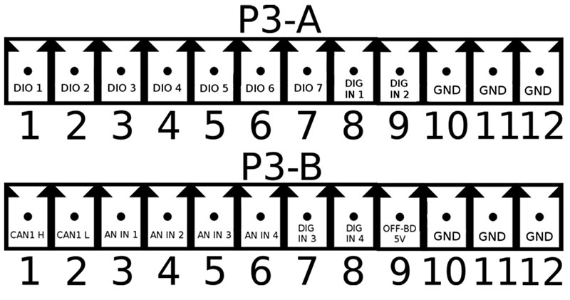
This single-board computer offers a wide variety of available access choices. With serial ports, Ethernet, and various wireless networking options, it’s an ideal controller for a remote sense and control network. Direct to our need for this article, the focus will be on two of the four screw terminal banks located at the “front” of the SBC.
Connections
In particular, we will be using DIO 1 at P3-A pin 1, GND at P3-A pin 12, and OFF-BD-5V at P3-B pin 9.
Using jumper wires for test purposes, loosen and remove the upper screw terminal with a small flat-head screwdriver (not shown). This will allow you to access the lower terminal to install the power wire.
Once these are done, we move on to wiring the servo.
Servo wiring varies between brand and model, but generally wires usually follow the same pattern: GND, power, signal (control). It’s best to check with the manufacturer if there’s any doubt, though.
Note: Some servos may need more power than the 5W the TS-7180 can provide. A separate power circuit must be devised under this circumstance. When powering externally, remember the TS-7180 and the servo must share a common ground.
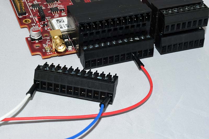
Terminal block P3-A removed to expose the lower screw terminal access; terminal blocks P3-A and P3-B wired with control, GND, and OFF-BD-5V wiring installed.
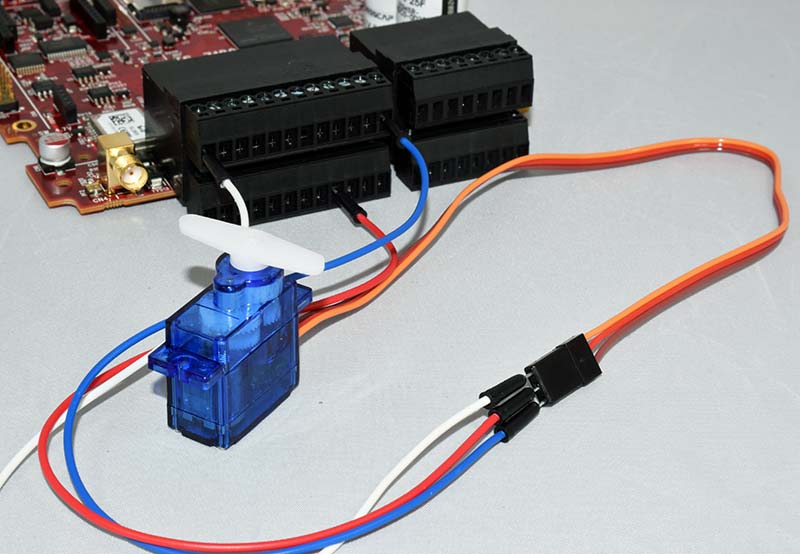
Servo wired to terminal blocks.
Software Setup
With the wiring completed, it’s time to set up some prerequisites. For the curious, you may have already checked the OFF-BD-5V signal and found it isn’t outputting anything! That’s actually okay.
That signal is designed for intrinsic safety, which means it starts out OFF. So, there are two main registers we need to set up before our servo will do anything. Run these:
tshwctl -a 309 -w 1
# this will turn on PWM, we’ll need that in a minute.
tshwctl -a 0x10 -w 3
# this will turn on power to the off-board 5V line.
These and all other commands are documented in the TS-7180 product manual. References are all in the Source Material section.
The Command Line Servo
While bit-banging a GPIO pulse train is technically possible, the device has a PWM generator already, so it makes more sense to save CPU time and use the built-in hardware. The TS-7180 uses the Linux PWM driver to operate the servo. This involves telling Linux which PWM chip to use, then setting the standard PWM parameters.
There is an interesting “gotcha” though: PWM’s duty cycle is not “high” or “low;” the PWM is implemented on an “assert”/”de-assert” way of thinking. Since this DIO is active-low, it starts high.
What this means is the PWM on DIO 1 is LOW on 100% duty cycle! Instead of giving the duty-cycle time in 1-2 ms with a ~20 ms gap, the duty cycle must be expressed in terms of 22.5 ms because the servo will be expecting a high-time of ~1-2 ms. (Again, with some variation. I suggest giving an extra 0.5 ms gap to ensure any potential jitter stays out of your 20 ms minimum low time.)
The math to choose your full period therefore is:
period = 20 ms + maximum sweep in ms
One servo we tested actually had 0.6 ms to 2.4 ms full sweep. So, in the case of this project, my full PWM period is 22.5 ms. Try this to center the servo (pulse width set to about 1.5 ms):
echo 0 > /sys/class/pwm/pwmchip4/export
echo 22500000 > /sys/class/pwm/pwmchip4/pwm0/period echo 21500000 > /sys/class/pwm/pwmchip4/pwm0/duty_cycle echo 1 > /sys/class/pwm/pwmchip4/pwm0/enable
That should center the servo. From this point, you can vary the duty cycle between ~20500000 and ~22400000 to find the true center and full effective sweep of the servo.
For the C-savvy programmer, each of the above echo targets are file handles and can be opened in your program for manipulation with a simple write() call.
Wrap-Up
Whether building a balancing robot, keeping a toddler out of daddy’s special stash, or designing the next great braking system for your soap box racer, servos are an essential component in any hobbyist’s or engineer’s toolbox.
With a little luck and a bit of exploration, hopefully this article has helped add a servo control trick or two to your embedded systems repertoire. SV
Source Material
General information about hobby servos
https://en.wikipedia.org/wiki/Servo_control
TS-7180 GPIO documentation
https://wiki.embeddedarm.com/wiki/TS-7180#GPIO
TS-7180 Terminal Block definitions
https://wiki.embeddedarm.com/wiki/TS-7180#Terminal_Blocks
TS-7180 PWM documentation
https://wiki.embeddedarm.com/wiki/TS-7180#PWM
Link to where to buy the constant rotation servo in the photo
https://www.pololu.com/product/2820
Article Comments