Ultrasonic Radar Refresher — Part 4
By Dan Harres, Max Harres View In Digital Edition
Parabolic Antennas
So far in our series, we’ve covered the basics of piezoelectric transducers, the transmitter electronics for driving the transducers, and the improved focusing of the ultrasonic energy into and out of the transducer using parabolic antennas.
This article focuses on the actual building of the parabolic antenna (the reflector) for the ultrasonic sensor. For this part of the project, I needed a little help with programming the CNC machine to create the wood mold. So, I turned to my son, Max. Max provided the Python programming that accomplished that task and co-authored this installment with me.
The Reflector
Last time, when the subject of parabolic antennas was introduced, it was mentioned that we currently use a mold carved from wood by a CNC machine to create the antenna. A sheet of heated plastic is then vacuum formed over the mold, and the resulting antenna just needs a hole cut in its bottom to allow the ultrasonic transducer through. So, the first thing that needs to happen is to create the mold.
Creating the Antenna Mold
A paraboloid-shaped antenna will produce an almost perfectly collimated beam of the ultrasonic transducer’s energy. We don’t need a full paraboloid (Figure 1).
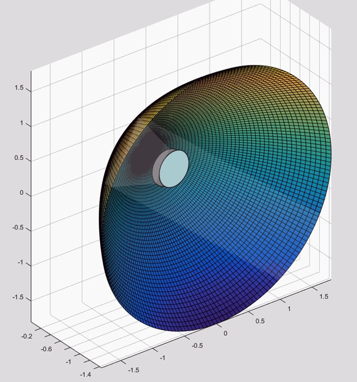
Figure 1. Full paraboloid with backfiring transducer.
A half paraboloid (Figure 2) with the ultrasonic transducer pointed up will still capture virtually all the transducer’s energy (because the transducer emits most of its energy in a ±30° cone).
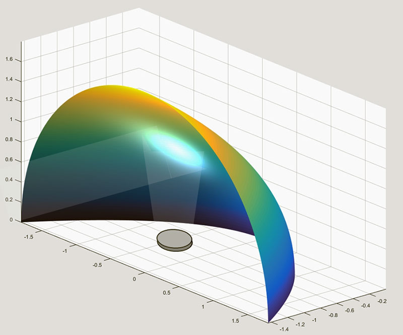
Figure 2. Half-paraboloid with transducer firing up.
We know from last time that this half paraboloid is the result of rotating a parabola (like the one in Figure 3) through 180° about the horizontal axis.
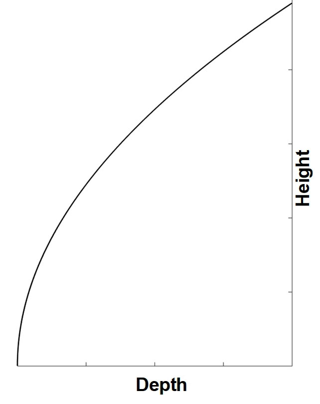
Figure 3. Parabola profile for generating the half-paraboloid.
However, to generate the paraboloid shape on the CNC, we’ll be working with the shape turned 90° clockwise as shown in Figure 4.
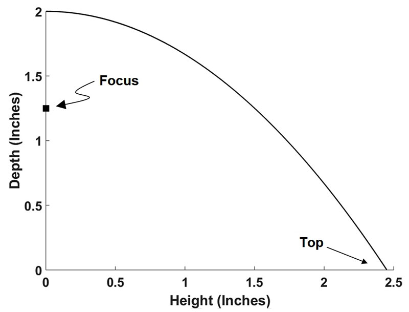
Figure 4. Parabola profile turned 90º on its side.
Dimensions
Remember that a parabola is defined by a second-order equation like this:
y = ax2
In Figure 4, the Y axis is labeled “Depth” and the X axis is labeled “Height.” The focus of a parabola is given by:

The focus is where the center of the ultrasonic transducer sits.
A nice size for a half-paraboloidal antenna on a small robot might be one that is, say, four inches wide and 2.5 or so inches high. If we make a = 0.333 and the maximum x = 2.5 inches, we will find from the above two equations the focus will be located at f = 0.75 inches (refer again to Figure 4) and the depth will be 2.08 inches (slightly larger than two inches).
Now, if we take the Figure 4 curve and rotate it through 180°, we arrive at the half paraboloid of Figure 2.
We now have the specifications for how to make the antenna mold. So, how do we turn that into a piece of wood with the correct CNC carving? In other words, we know what the shape of the wood mold should look like, but how do we get a machine to do that for us?
Usually, when someone wants to create something with a CNC machine, they use CAD/CAM programs (Roger Secura's article has a good introduction to using CNC). The final result of the CAD/CAM process is called G-code, which is just a long series of text commands that instruct the CNC machine to move in straight lines (G00 or G01 commands) or in clockwise (CW) or counterclockwise (CCW) arcs (G02 or G03 commands, respectively).
We’re going to skip the CAD/CAM step for this project and use the mathematical equations for a parabola and the fact that we just want to rotate through 180° to write a program in a high-level programming language to create the G-code statements that will drive the CNC machine. The programming language we’ve chosen is Python, although C or some other language would work just as well.
The Python program is shown in Listing 1.
import math
fileID = open(‘gcodeSmallParaboloid.txt’,’w’)
fileID.write(‘For now, negative Z is up \r\n’)
fileID.write(‘G20 \r\n’)
fileID.write(‘F25 \r\n’)
fileID.write(‘G54 G90 M03 (Select coordinate system, absolute mode \r\n’)
fileID.write(‘G00 Z-0.1 \r\n’)
for i in range (1, 64):
depth = i*0.032
radius = math.sqrt(depth/0.333)
clockwise = 1
Xend = -radius
y = 0
if radius > 1.25:
Xend = -1.25
temp = math.acos(1.25/radius)
y = radius*math.sin(temp)
absXend = abs(Xend)
fileID.write(‘G00 X’ +
str(“{:,.3f}”.format(Xend)) + ‘ Y’ +
str(‘{:,.3f}’.format(y)) + ‘\r\n’)
fileID.write(‘G02 X’ +
str(‘{:,.3f}’.format(-Xend)) + ‘ Y’ +
str(‘{:,.3f}’.format(y)) + ‘ R’ +
str(‘{:,.3f}’.format(absXend)) + ‘\r\n’)
fileID.write(‘G03 X’ +
str(‘{:,.3f}’.format(Xend)) + ‘ Y’ +
str(‘{:,.3f}’.format(y)) + ‘ R’ +
str(‘{:,.3f}’.format(absXend)) + ‘\r\n’)
fileID.write(‘G00 Z’ +
str(‘{:,.3f}’.format(depth)) + ‘\r\n’)
for j in range (i, 64):
if radius < 2.45:
x = radius
y = 0
if abs(radius) > 1.25:
x = 1.25
temp1 = math.acos(1.25/radius)
y = radius*math.sin(temp1)
fileID.write(‘G00 Y’ +
str(‘{:,.3f}’.format(y)) + ‘\r\n’)
Xend = x
if clockwise == 1:
fileID.write(‘G00 X’ + str(‘{:,.
3f}’.format(-Xend)) + ‘\r\n’)
fileID.write(‘G02 X’ + str(‘{:,
.3f}’.format(Xend)) + ‘ Y’ +
str(‘{:,.3f}’.format(y)) + ‘ R’ +
str(‘{:,.3f}’.format(radius)) +
‘\r\n’)
else:
Xend = -x
fileID.write(‘G00 X’ + str(‘{:,
.3f}’.format(-Xend)) + ‘\r\n’)
fileID.write(‘G03 X’ + str(‘{:,
.3f}’.format(Xend)) + ‘ Y’ +
str(‘{:,.3f}’.format(y)) + ‘ R’
+ str(‘{:,.3f}’.format(radius))
+ ‘\r\n’)
radius = radius + 0.034
clockwise = -clockwise
fileID.write(‘G00 Z-0.1 \r\n’)
fileID.close()
Listing 1: Gcode creating program.
The program works like this: It first writes a G02 (CW arc) command to the G-code file. This first G02 command creates a semicircle arc that will remove the material at a 0.032 inch depth with a radius of 0.31 inches.
The program then writes a G03 (CCW) arc command with a slightly larger (by 0.04 inches) radius than the previous G02 command. It continues to send alternating G02 (CW) and G03 (CCW) commands with increasingly-larger radii until all the material at this first layer is removed.
Next, the program commands the CNC machine to go 0.032 inches deeper. The initial G02 (CW circle) command this time specifies a radius that is 0.04 inches larger than the initial radius before (that is, it is now 0.35 inches).
As previously described, it then sweeps the CNC router in ever-increasingly larger arcs until all the material at this depth has been removed. Figure 5 shows the CNC machine in action.
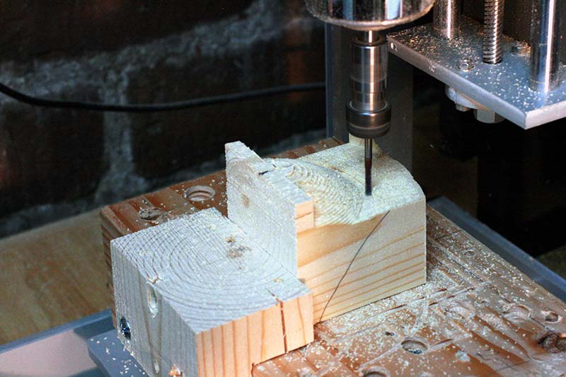
Figure 5. CNC machine removing wood layers by routing small arcs.
The CNC machine operating from instructions in the Gcode file (which, in turn, was created by the Python program in Listing 1) keeps removing material in these ever-larger sweeps until it reaches the final depth of 2.08 inches.
Of course, the profile that the CNC machine is cutting isn’t exactly that of Figure 4. That figure shows a continuous parabolic curve, but the CNC machine works in the digital world and produces quantized steps like those of Figure 6.
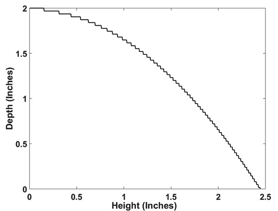
Figure 6. Actual finished profile of the mold showing quantized steps.
As long as the steps in the quantized mold are small relative to the wavelength of the ultrasonic energy (for 40 kHz ultrasonic transducers, the wavelength is approximately 0.3 inches and for 25 kHz transducers, it is approximately 0.5 inches), the difference in performance between this real world shape and the theoretically perfect shape is insignificant.
The finished mold is shown in Figure 7.
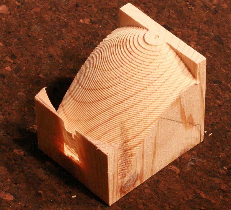
Figure 7. Final antenna mold.
Notice one more thing about the mold that wasn’t mentioned earlier: The sides of the half-paraboloid have been cut off. This is because most ultrasonic transducers distribute the majority of their energy within a cone of only about ±30°, so that virtually no energy reaches the left and right extremes of the half-paraboloid antenna. Figure 2 depicted this situation of a transducer producing a cone of energy.
Truncating the half-paraboloid by removing an inch or so from each side results in shorter CNC routing times and produces a more compact antenna. The Python program in Listing 1 includes the limits needed to produce this truncated mold, so no further trimming of the mold is required to achieve this shape.
The mold created by the CNC machine in Figure 7 has excess wood at the front and back and on the bottom that can be trimmed off with a saw. Also, the ridges created by the CNC’s stepped routing can optionally be filled in with wood putty, which can then be sanded to produce a smooth shape (Figure 8).
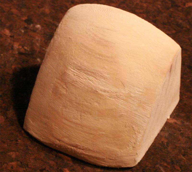
Figure 8. Mold after trimming excess and filling in with wood putty.
Forming the Plastic Reflector
Once we have a mold made, we can form the reflector. If you’re new to vacuum forming plastic, here are the materials you’ll need to do this:
- A toaster oven dedicated to this purpose only — once you’ve started heating plastics in the oven, don’t use it for food!
- A shop vac (the one you use to clean your work area is just fine).
- A box of some kind (mine’s made from wood) with holes in the top and a port where the shop vac tube is inserted.
- A frame that will hold the sheet of plastic; this should fit snugly over the box.
- Plastic sheet — ABS or polystyrene are the kinds I’ve used, but there are others.
That’s it! For the cost of a second-hand toaster oven and a little hardware, you’ve got yourself the ability to form plastic stuff. The metal frame shown in Figure 9 is made from 1/2” aluminum angle (aluminum is much easier to cut than steel), some small metal brackets to form the corners of the frame and hold the angles together, a couple of small hinges, and some nuts and bolts.
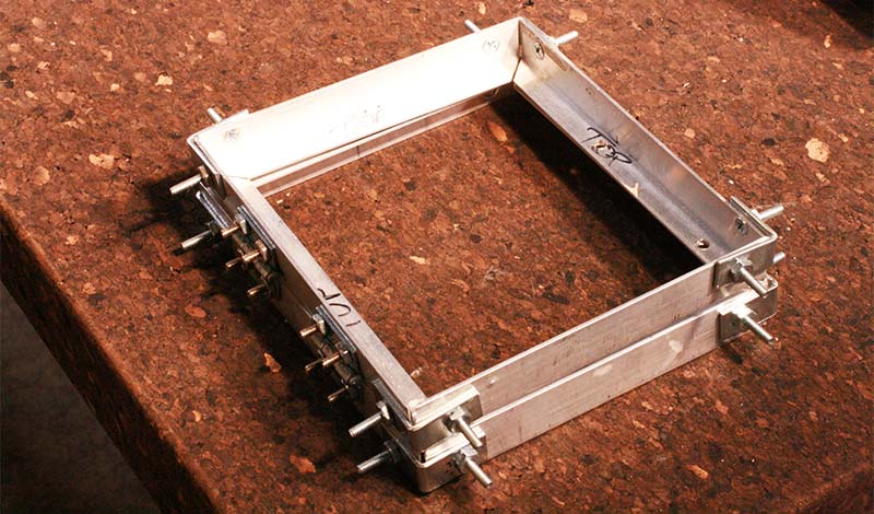
Figure 9. Frame for holding plastic.
You may have to make some modifications to the toaster oven so that it will accept your frame. For example, on our setup, we cut out the center of the removable grill on the toaster oven and fashioned a wood fixture to hold the plastic sheet and frame so that it was in about the middle of the toaster (Figure 10).
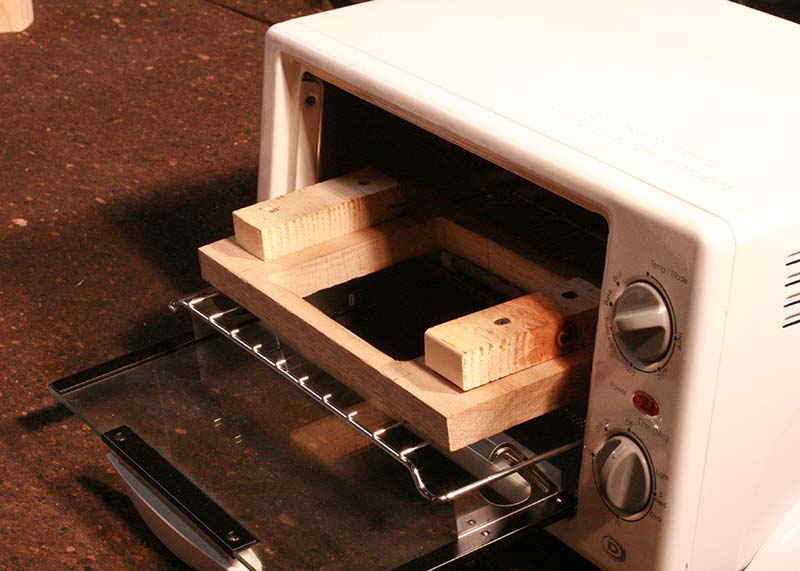
Figure 10. Wood fixture to hold the frame higher in the toaster oven.
That way, when the plastic heats up in the toaster oven and starts to sag, it doesn’t touch the lower heating element.
The vacuum box is just four pieces of wood glued down to another sheet of wood and then covered with a piece of MDF on top with lots of holes drilled in it (Figure 11).
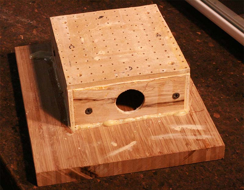
Figure 11. Vacuum box over which the frame and heated plastic are placed.
You also need to cut a large hole on one side that is just slightly larger than the nozzle on your shop vac.
When the shop vac hose nozzle is pushed into the box and the shop vac is turned on, it pulls a vacuum through the holes in the MDF top. With the mold in place on top of the box, the hot plastic sheet is pulled down over the mold and forms (Figure 12).
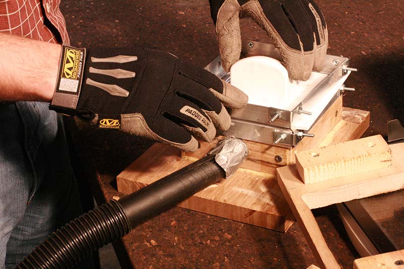
Figure 12. Heated plastic is pulled down over the mold by vacuum.
Plastic sheet comes in lots of different thicknesses, so you’ll have to experiment a little to see what works best — too thin and the plastic might tear during forming or you might wind up with a flimsy reflector; too thick and the plastic might not want to form properly. We’ve had good luck for the reflector described here with 0.125 inch High Impact Polystyrene (HIPS).
Figure 13 shows the final (uncut) formed plastic reflector.
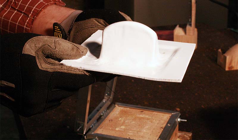
Figure 13. Plastic reflector after forming.
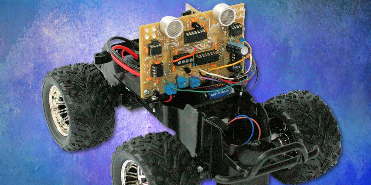
After cutting the excess off and cutting a hole in the bottom for the ultrasonic transducer to fit through, the completed assembly results are shown in Figure 14.
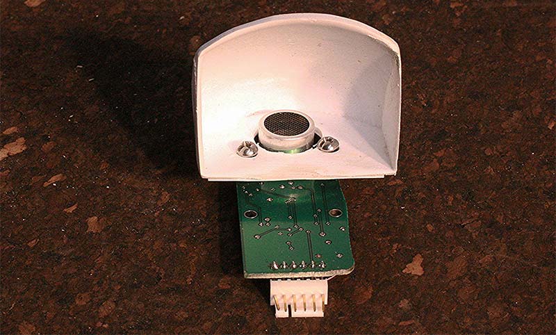
Figure 14. Completed parabolic reflector attached to circuit board.
Test Results for the Reflector
At this point, it’s fair to ask: Just what is the advantage of using a parabolic reflector in ultrasonic applications? After all, the process of creating a mold for the reflector, then vacuum forming the reflector from plastic is not a trivial process.
To answer this, the experimental setup shown in Figures 15 and 16 was used.
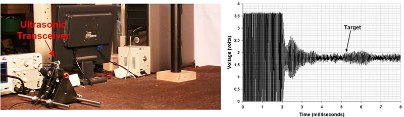
Figure 15. Ultrasonic transceiver without reflector (a) and output(b).
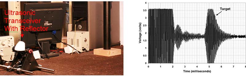
Figure 16. Ultrasonic transceiver with reflector (a) and output(b).
A dowel rod of approximately two inch diameter was placed at a distance of about 30 inches from the ultrasonic transceiver. The dowel rod target was deliberately placed close (about 10 inches) to test equipment to simulate the “clutter” that is typical in ultrasonic sensing applications.
In the Figure 15 setup, no reflector was used. As the oscilloscope output shows, the target return was so very small that it was indistinguishable from the clutter returns of the nearby equipment.
With the exact same setup — but with a reflector mounted on the board (with the board now oriented horizontally) — the experiment was repeated (Figure 16). The clutter appears to be similar to the “No Reflector” configuration, but the target now produces a much larger return (so large, in fact, that it saturates the receive amplifier).
The reflector makes the difference between a small return buried in clutter and noise, and a large return easily identified as an object.
What’s Next?
There are still some loose ends that need to be tied up for this series. For one thing, we haven’t discussed the receiver electronics or the microcontroller. Plus, a very important aspect of the parabolic ultrasonic radar that needs to be examined is the ability to perform two-dimensional location of objects. This will be covered in the remaining article. SV
Article Comments