Ultrasonic Radar Refresher — Part 3
By Dan Harres View In Digital Edition
The first two articles in this series focused on the physical characteristics of the ultrasonic transducer and the associated electronics needed to drive it. This time, we’ll look at ways to enhance the performance of the ultrasonic transducer.
Limitations of Ultrasonic Ranging
If you’ve used ultrasonic ranging modules in the past — particularly the “cheapie” versions — you’re probably aware that their performance is somewhat hit-or-miss. They can produce both “false alarms” — indications of an object in their path when none exists — as well as “missed detections.” Some of this may have to do with the design of the unit. However, at least some of it is inherent in how ultrasonic transducers work.
False Alarms Caused by a Wide Field-of-View
Because most ultrasonic ranging transducers have just a small diaphragm for moving the air, the acoustic wave front produced winds up traveling not just to the diaphragm but to the sides as well (Figure 1).
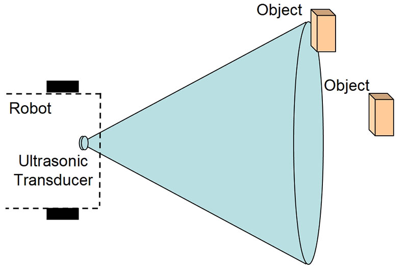
Figure 1. The wide field-of-view of a typical ultrasonic transducer means that it will “see” objects that are not in the path of the robot.
Typical transducers will exhibit as much as half their power at angles of ±30°.
As a result, the transducer will “illuminate” objects that are not in the path of interest. These “objects” can include such things as floor irregularities. Also, acoustic energy can be reflected by one object to another — a phenomenon referred to as multipath interference. The resulting time-of-flight will be meaningless or misleading.
Significant Fall-off in Amplitude with Increasing Range
Another challenge in ultrasonic ranging applications is the rapid drop in amplitude as a function of range. The reason for this can be seen in Figure 2.
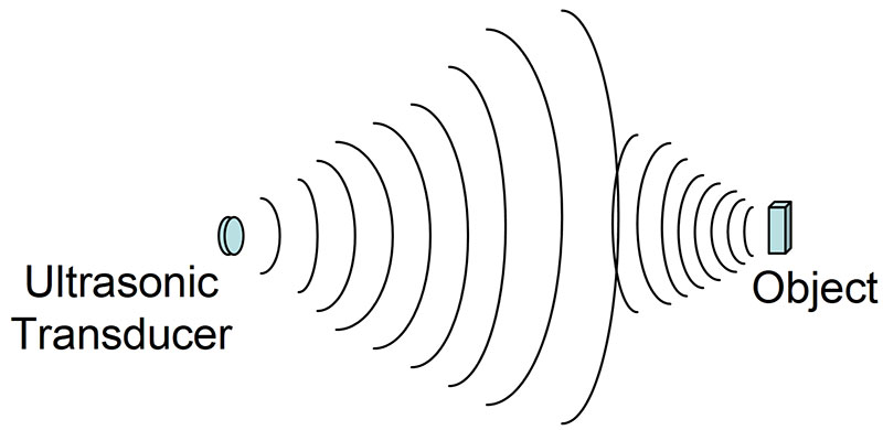
Figure 2. Both the originating energy and the echo fall off at 1/r2 rates.
The energy scatters from the transducer in both the horizontal and vertical axes. Thus, it falls off at a 1/r2 rate, where r is the distance to the object.
Reflecting from the object, the echo also scatters and falls off at a 1/r2 rate. The overall signal return amplitude therefore changes as a function of 1/r4. As a result, the dynamic of the signal over the working range of the ultrasonic system is often huge.
Lack of Bearing Information
Simple ultrasonic ranging gives range information but not bearing information. As a result, the robot or other user of the information knows how far away the object is but has no idea whether the object is to the left or to the right. In many collision avoidance applications, such additional information is needed to determine the proper diversionary action to take.
Improving the Ultrasonic Ranging Performance
How can we improve on the simple ultrasonic transducer’s performance? We can take a hint from the way in which RF (including microwave) radar makes possible detection at very long distances: by using an antenna.
The Parabolic Antenna
Most commercial RF radar sets (for example, the ones utilized at airports) use a parabolic reflector to focus the energy from the transmitter to the object (usually referred to as “the target” in radar applications), and use the same or a similar parabolic reflector to focus incoming energy from the target back onto a receiver.
Why a Parabola?
The parabola has the unique feature that any path from the parabola’s focus reflected from the parabola will travel the same distance. Thus, the two paths shown in Figure 3 are equidistant.
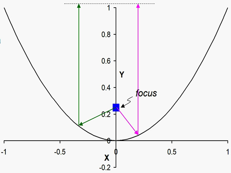
Figure 3. Both the green and magenta paths are the same distance from the focus to the dashed horizontal line at the top.
In general, a parabola will have a second-order equation in x, like this:
y = ax2 + bx + c
Although the parabola in Figure 3 has the simpler equation:
y = x2
The focus for this parabola is at x = 0, y = 0.25. As a fun trigonometry problem, see if you can prove that the distance traveled from the focus to the dashed line is a constant and is independent of where on the parabolic curve the projected beam strikes.
Note that the parabola works the same way in reverse. A line parallel to the y axis coming toward the parabola will reflect to the focus.
Turning the Parabola into a Parabolic Antenna
To make a parabolic antenna, we take the two-dimensional parabola of Figure 3 and rotate it about the y axis (referred to as the “axis of symmetry”). Figure 4 shows such a reflector (y axis is pointing out).
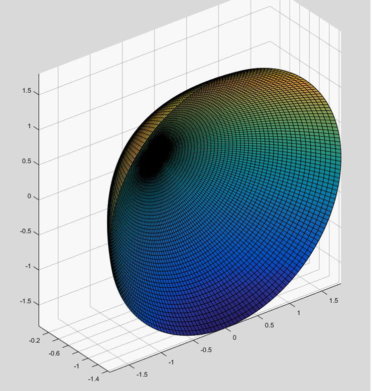
Figure 4. Paraboloid formed by rotating a parabola about the y axis.
Using such a paraboloid as the antenna, the ultrasonic transducer is placed at the focus, with the transducer in a backfire configuration (that is, the transducer is pointing in the –y direction, as in Figure 5).
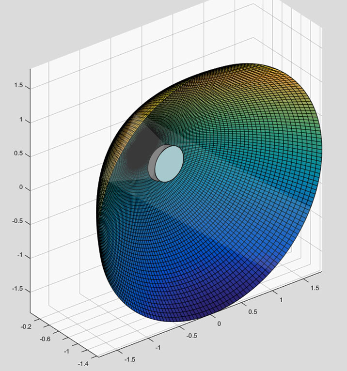
Figure 5. Ultrasonic transducer firing into the antenna, with collimated energy out.
Because all reflections are parallel to the y axis and have a constant time-of-flight exiting the antenna, a nearly-collimated beam is produced.
Note that energy parallel to the y axis coming into the paraboloid (that is, received energy) will also converge at the transducer.
Paraboloids in the Wild
Before going further in discussing ultrasonic radar antennas, let’s think about where paraboloid reflectors occur in nature. One obvious answer is with animals that rely heavily on their sense of hearing for tracking prey or communicating with other members of their pack.
The outsized ears of the African wild dog (Figure 6) are an example.

Figure 6. Parabolic (approximately) ears of an African wild dog.
Note that their ears form a slightly elliptical paraboloid in which the horizontal axis is somewhat smaller than the vertical axis.
Making the Parabolic Antenna More Practical
Okay, back to our ultrasonic radar antenna. The parabolic reflector of Figure 5 has several problems that we should consider.
First, the transducer (which in the figure is shown just floating in space) will have to be suspended somehow in that position. This means adding struts from the reflector to hold the transducer at its focal position.
Second, once we have the transducer and struts in place, we will obstruct some of the reflected energy that is supposed to be going to or from the transducer.
Third, the parabolic reflector will have to be supported to keep it vertical. This is equivalent to keeping a small bowl sitting on its edge, and will require a fairly substantial structure to reliably keep the reflector in place.
Half a Reflector Works Better than a Full Reflector
Since most ultrasonic transducers have a field-of-view of only about ±30°, we really don’t need the full surround of the Figure 5 parabolic reflector. Instead, we can cut that reflector in half, point the transducer up instead of back, and we wind up with the configuration in Figure 7.

Figure 7. The half-paraboloid reflector.
Note the advantages: The transducer sits on the board supporting the half reflector, so no struts are needed; The transducer is not in the path of the reflected energy; and, The half reflector can rest on its bottom perimeter, providing a very stable mount.
In fact, the reflector can be reduced still further by recognizing that almost none of the ultrasonic energy will make it to the right or left extremes of the paraboloid. Consequently, the reflector shape can be truncated by cutting off those outer areas.
Figure 8 shows such a truncated parabolic reflector installed atop its transducer and circuit board (Figures 9a and 9b).
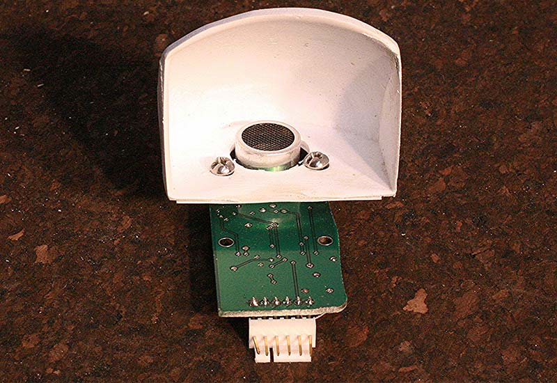
Figure 8. Ultrasonic transducer with truncated paraboloid reflector.
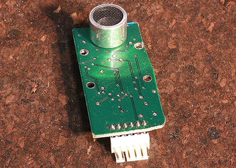
Figure 9A. (a) Transducer side and (b) circuit side of the Figure 8 electronics.
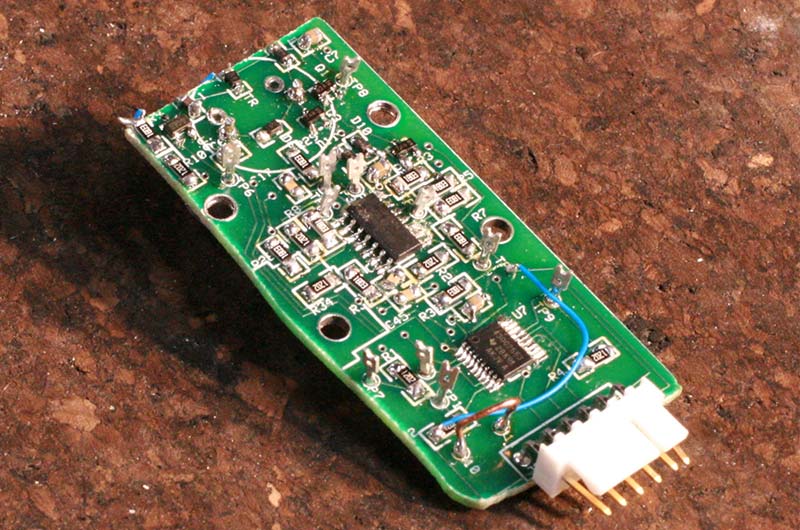
Figure 9B. (a) Transducer side and (b) circuit side of the Figure 8 electronics.
This particular reflector was vacuum-formed from a polystyrene sheet using a mold carved from wood using a CNC router (Figure 10 shows the mold).
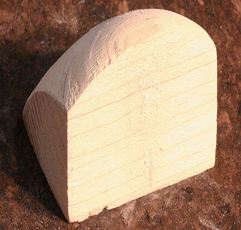
Figure 10. Wooden mold for the truncated paraboloid reflector of Figure 8.
The reflector shown is the smallest of these I’ve made. The largest is approximately 3.5 inches across.
What’s Next?
At this point in the development of parabolic reflector-enhanced ultrasonics, things are still in the prototyping stages, so I’m not quite ready to release details of the electronics and the physical build of the reflector. However, by next time, I will have full details about the schematics, the microcontroller software code, and the reflector.
I will also describe the development of a modification of the parabolic reflector that allows the robot to determine not only how far away the object is (range), but the bearing as well. SV
Article Comments