Ultrasonic Radar Refresher
By Dan Harres View In Digital Edition
Robots commonly performing obstacle detection rely on active sensing. That is, they project energy of some type — whether light, RF, or acoustic — in the direction of the possible target and measure the reflected energy returned to a receiver.
Let’s discuss ultrasonic methods for object detection by going over some fundamentals. We’ll start by talking about the general situation of detecting objects.
Humans (and some machines) use vision and to a lesser extent hearing to avoid collisions or otherwise detect objects in their path. In that case, the system is using passive light energy or passive acoustic energy to detect objects.
Most machines performing obstacle detection rely on active sensing. That is, they project energy of some type — whether light, RF, or acoustic — in the direction of the possible target and measure the reflected energy returned to a receiver.
When the energy is in the RF region of the electromagnetic spectrum, this type of system is called RADAR (RAdio Detection And Ranging). The term radar is also sometimes used when the energy is in the light part of the electromagnetic spectrum; in this case, it’s sometimes called LIDAR (LIght Detection And Ranging) or LADAR (LAser Detection And Ranging).
When the energy is in the ultrasonic region of the acoustic spectrum, the term “ultrasonic radar” is used. That’s what we’ll be talking about here.
Just What is Ultrasonic Energy?
Ultrasound is acoustic energy propagated at frequencies above human hearing; generally 20 kHz to several GHz. Let’s break that down a little more.
Acoustic propagation refers to the transmission of sound through changes in the pressure levels as the energy travels through some type of medium such as air or water (we’ll concentrate on air).
It travels through the air at the speed of sound, which is on the order of 343 meters per second at standard temperature and pressure (20°C at sea level).
To illustrate what is meant by frequency, we can use the example of a piano. You know that the keys at the extreme left of an acoustic piano are referred to as the “low notes.” Their very deep bass tone is the result of the metal strings that the associated hammers strike, causing them to oscillate at “low frequencies.”
This means the string vibrates from peak to peak a very small number of times per second. The lowest of a concert piano’s notes are vibrations that oscillate only about 30 times per second; these are referred to as 30 Hz.
At the extreme right side of the piano keyboard are the “high notes.” These notes have strings that — when struck with the associated hammer inside the piano — vibrate at frequencies as high as 4,000 times per second (4,000 Hz).
People with normal hearing can detect the entire range of piano notes, and some folks can even detect frequencies as high as 20,000 Hz.
Beyond this frequency of 20,000 Hz, humans do not hear the sound (many animals, however, have hearing to frequencies far beyond this limit). Because the sound cannot be heard by humans, it’s possible to propagate considerable energy at these frequencies without annoying people or otherwise interfering with their normal activities.
Creating Ultrasonic Energy
So, how do we create ultrasonic waves? Typically, this is done with a transducer, which takes electrical energy modulated at the appropriate frequency and converts this to mechanical energy that moves a surface, creating the acoustic propagation.
A common type of hobbyist ultrasonic transmitter is a piezoelectric ceramic transducer, typically operating at 40 kHz. Such a piezoelectric device has the unusual property that it expands or contracts as the voltage across it increases or decreases.
Therefore, by driving it with an AC voltage, the device’s surface in a particular axis moves with respect to the opposite surface.
Such a device can be made to change its dimensions at 40 kHz and above. In addition, the device can be manufactured so that it is “resonant” at a specific frequency.
How Does Resonance Work
In order to understand piezoelectric ultrasonic devices, we need to understand resonance. Lasers, microwave ovens, that squeal your car makes burning out causing the neighbors to stare — these are all examples of resonance. One example that we’re all familiar with is a child swinging (Figure 1).
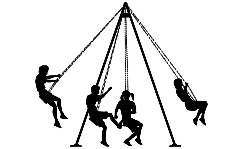
Figure 1. Swinging requires the use of resonance.
A child merely pushing with their feet from a starting position causes the swing to move only slightly. To make the swing move great distances requires the child “to swing.” What this really means is that the child must learn to move the lower legs forward or backward in synchrony with the swing’s movement.
When the swing reaches its backward-moving limit, the child rapidly rotates the lower legs forward and, likewise, at the forward-moving limit, the lower legs are quickly moved back. In this way, additional energy is imparted to the swing with each iteration, resulting in a large steady-state “amplitude.”
Before we leave this resonance example, let’s think about one more aspect of the situation that is typical of all such resonant systems.
The system (in this case, the child and the swing) has a natural frequency at which it operates. The swing and the child, in fact, constitute a pendulum. The natural frequency of this system depends only on the length of the swing chains.
In the case of a piezoelectric device, the device’s natural frequency is determined by its dimensions and the device material. Consider the situation when a voltage is generated across the device.
The wall of the device moves, creating a wavefront that moves through the device, striking the opposite wall of the device, then heading back to the originating wall. This roundtrip time of travel constitutes the period of the natural frequency.
If we vary the voltage across the device at this natural frequency, we create a resonant behavior within the device, much like the child on the swing. After several periods of such voltage change, the amplitude of the wall movement (and therefore the transmitted sound) becomes relatively large.
Sensing Ultrasonic Energy
Okay, so a piezoelectric transducer can convert electrical energy into mechanical energy and thereby allow us to create ultrasonic pulses. But how can we sense ultrasonic energy?
It turns out that the same type of piezoelectric transducer that was used for electrical-to-mechanical transformation can be used to do the opposite. When piezoelectric devices are subjected to external force, the device generates a voltage which can be amplified and detected.
In fact, some applications use a single transducer in a half-duplex mode to transmit a sequence of pulses and then “listen” for the return of those pulses (such a circuit will be discussed later in this series).
Most applications use separate transducers for transmit and receive. Although the force to which the piezoelectric transducer receiving the acoustic wave is small and the associated output voltage is low amplitude, an amplifier with sufficient gain raises the amplitude to a useable level.
Ultrasonic Ranging
Simple radar applications use Time-of-Flight (TOF) to determine distance to an object. This is a fairly straightforward calculation. In the case of ultrasonics, the wavefront travels to the object, then back to the ultrasonic receiver, at the speed of sound. So the distance is simply given by:

where D is the distance and c is the speed of sound (343 meters per second).
Unfortunately, the calculation is muddied a bit by the fact that it may not be exactly clear how to make the TOF measurement.
Figure 2 shows typical transmit and receive waveforms for an ultrasonic transducer.
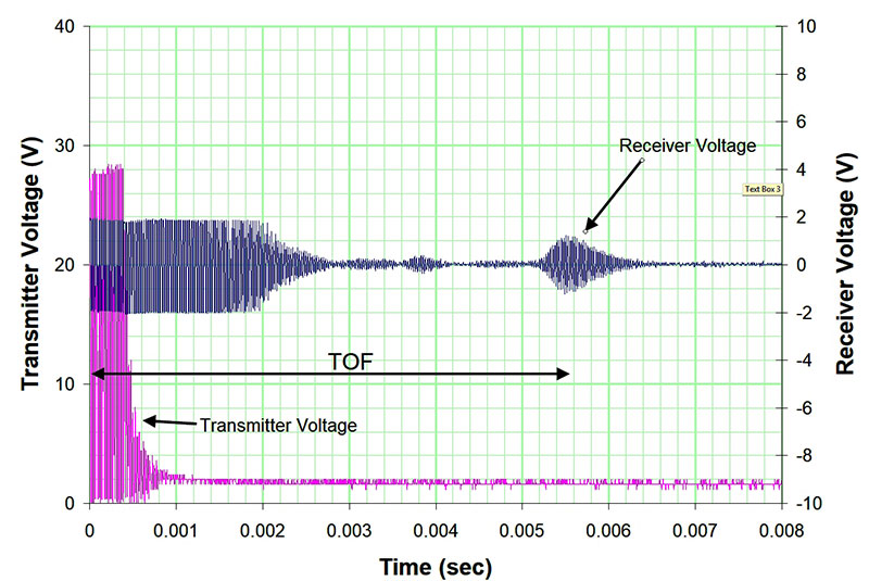
Figure 2. Transmit and receive signals.
We reasonably choose the start of the transmit signal as the beginning of the time-of-flight, but where should we choose to say time-of-flight ends? Perhaps we should use the start of the reflected waveform. Or, the peak.
Issues with Ultrasonic Detection
We’ve already mentioned the ambiguity in determining TOF, but this is a relatively minor issue, since it generally results in an uncertainty of less than an inch which — for many hobbyist robot applications — is tolerable.
Other issues, however, are more serious. These include clutter, a return signal that falls off rapidly with distance, and transmitter ringdown.
Clutter
Clutter is a potential problem in any radar application, but particularly a problem with ultrasonic applications because of the wide field of view (FOV) of the ultrasonic devices.
Figure 3 shows a directivity graph that is similar to the charts for most ultrasonic transmitters.
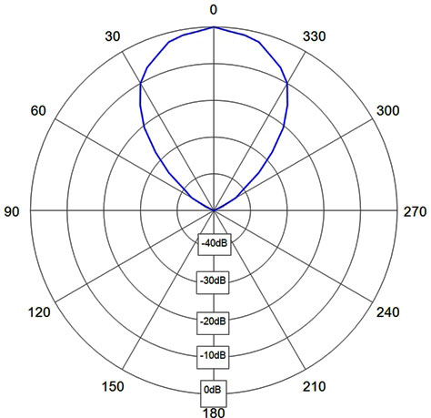
Figure 3. Directivity graph for a typical ultrasonic transmitter.
The figure shows that the transmitter still has about 1/10 its power at ±30° from boresight.
Such a large FOV means that the device can “see” not only pertinent objects in front of it but also irrelevant objects far from the robot.
In fact, the ultrasonic response shown back in Figure 2 is an example of this. In that particular application, the transmitter/receiver was mounted about four feet above the floor.
It was pointed directly at a target about five feet away (the second of the two largest responses).
A fluorescent light fixture hanging from the ceiling a couple of feet above the transmitter/receiver was actually causing the first large response. The transmitter/receiver responded to this light fixture because it was within its field of view.
Such “false alarms” reduce the reliability of the ultrasonic sensor’s results and often lead to the conclusion that ultrasonic sensors make poor ranging devices.
Ringdown
Another problem plaguing ultrasonic transmitters is the fact that they cannot immediately stop their movement when the voltage stops changing.
This is related to their resonant nature. Just as a child swinging cannot immediately stop but must instead let the swing slowly lose energy, the piezo transmitter must likewise slowly stop its movement.
Figure 4 shows an ultrasonic transducer subjected to a 0 to 30V square wave and then — mid-screen — switched to a high-impedance connection.
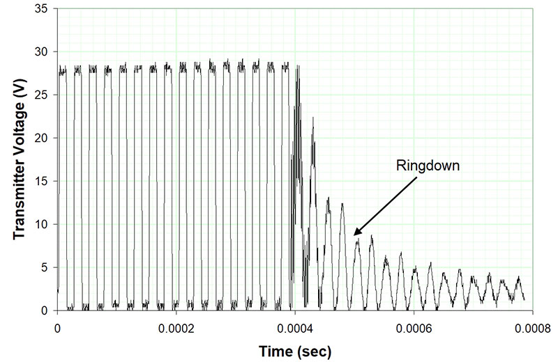
Figure 4. Transmitter subjected to 16 periods of square wave showing ringdown.
The transmitter continues to oscillate, generating voltage as it slowly “winds down.”
The reason this is important is that ultrasonic receivers often have a difficult time distinguishing between the signal produced by ringdown and an actual return from a very close object.
As a result, most ultrasonic receivers establish a “dead time” during which the receiver does not attempt to identify targets. Thus, most ultrasonic sensor systems cannot identify objects that are very close.
Significant Signal Attenuation with Distance
A signal sent through the air will diminish as a function of distance. So, just how fast will the ultrasonic signal diminish? We’ll ignore acoustic absorption of air since this is a relatively minor effect at distances of a few feet, and instead just concentrate on signal attenuation as the result of wavefront expansion.
Figure 5 depicts what is happening.
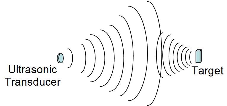
Figure 5. Ultrasonic transmission and signal return.
We know that the wavefront expands in both dimensions normal to the transmission axis. So, the signal is proportional to (1/r2), where r is the distance from the transducer.
Once the wavefront hits the target, it’s dispersed by the target and similarly expands, also resulting in a decrease in signal as a function of r2. So, the signal experiences a 1/r4 overall reduction.
Thus, if the return from the target at a two foot distance is S, at twice that distance (four feet) the signal will be down to S/16.
It’s easy to see that a return signal that is a relatively large amplitude one or two feet away may require a huge gain increase or other non-trivial processing method to be reliably recognized at, say, 10 feet.
Final Thoughts
With all of these problems, it’s not surprising that hobbyists sometimes find using ultrasonic devices frustrating. Fortunately, these issues can be solved with some basic understanding about how they function, making them a popular choice for obstacle detection and avoidance in robotic applications. SV
Article Comments