The Servo Buddy
By Jim Stewart View In Digital Edition
This article introduces servo motor construction and operation, and describes an inexpensive circuit you can build to control a servo without a microcontroller.
When I first started to build projects with R/C servo motors it became clear that, during construction, I needed a way to set the position of a servo manually. You can’t just grab the shaft and turn it, and writing software for a micro was overkill. Just a simple little circuit would do the job. That was the birth of the Servo Buddy.
First, let’s review some basics.
RC Servos
An R/C servo (or just servo) is an electro-mechanical device used to rotate an actuator to a precise position and hold it there, even if the actuator is pushing back. R/C stands for Radio Control since originally these servos were used for radio control of model airplanes.
Standard ranges of rotation are 90 degrees and 180 degrees. Figure 1 shows a Hitec model HS-5645MG servo.
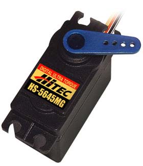
FIGURE 1.
Note the three wires near the actuator. They are power, ground, and input. While servos made by Hitec and Futaba are very popular, you will find servos from other companies, especially from China.
Servos come in two basic types: the original analog type and the newer digital type. Both types look similar from the outside and also have the same basic parts on the inside. The difference between analog and digital servos is in the electronics. Digital servos contain a microprocessor.
Connectors
Figure 2 shows a Hitec S-type connector and a Futaba J-type connector.
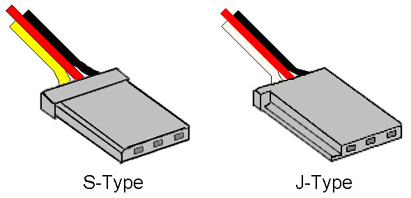
FIGURE 2.
They are almost the same except for a polarizing key along the edge of the Futaba connector. They mate with standard 0.025 inch square pins on 0.1 inch centers. The sequence of wires is the same, but the colors differ.
Voltage (typically +5V) is the center red wire. Ground is the black wire. The input signal is either yellow (S-type) or white (J-type). For other servo brands, the colors may differ.
Parts of a Servo
Figure 3 shows a simplified view of what’s inside a servo.
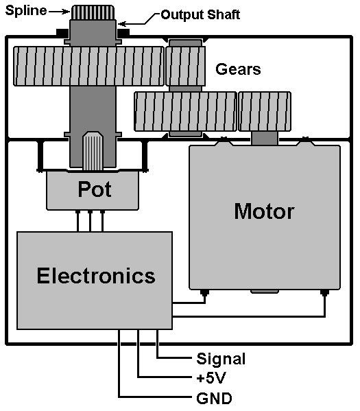
FIGURE 3.
A small DC motor is connected to an output shaft through a set of speed-reduction gears. The power of a motor is P = kwG, where k is a constant, w is the rpm, and G is the torque. If power is fixed, then reducing speed will increase torque on the output shaft.
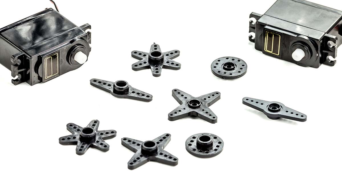
The motor is controlled by the electronics. A position command is the input, while a potentiometer on the shaft provides position feedback. The actuator — commonly called a horn — has grooves in its mounting hole that mate with the spline at the end of the output shaft.
The spline prevents the horn from slipping under torque. A screw attaches the horn to the shaft. Horns come in various shapes: arms, bars, crosses, discs, etc.
Note that the spline on a Hitec servo has 24 grooves while the spline on a Futaba servo has 25. Their horns aren’t interchangeable.
Input Signal
The control input is a pulse width modulated (PWM) signal as shown in Figure 4.
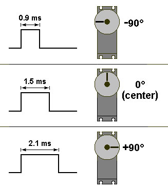
FIGURE 4.
For an analog servo, the pulses are typically 20 milliseconds apart for a repetition rate of 50 Hz. Digital servos use the same PWM widths but can use a higher repetition rate, up to 300 Hz.
The pulse widths shown are common, but other widths are also used. Check the particular manufacturer’s datasheet.
Analog Servo Electronics
Figure 5 shows a block diagram of the electronics of an analog servo.
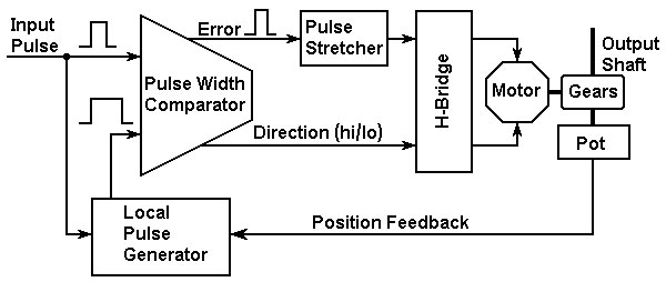
FIGURE 5.
The local pulse generator (triggered by the input pulse) generates a pulse width proportional to the current position. The local pulse and the input pulse go to a comparator which subtracts one from the other. The difference is the error pulse.
The direction signal depends on which pulse was wider. The error signal goes to a pulse stretcher which, in effect, is an amplifier. So, a 1% difference in width from the comparator can generate a 50% drive to the H-bridge. The H-bridge sets the polarity of the voltage going to the motor according to the direction signal. The percent drive to the H-bridge decreases as the position approaches the command point.
To prevent “hunting” (an oscillation around the final position), there is a small dead-band. Once the difference between the command point and position is within the dead-band, the motor drive goes to zero.
Gear Material
Three types of material are used to make gears form RC servos:
- Nylon: The most commonly used. Nylon gears are lightweight and run smoothly with low wear, but are at the low end in durability and strength.
- Metal: The strongest material. Metal gears are heavy and, due to wear on the teeth, will develop “slop” (looseness) in the gear train. Slop causes loss of position accuracy and sometimes causes a mechanical instability or oscillation under certain types of load. If you have the money, titanium gears offer superior wear resistance.
- Karbonite: Carbon reinforced plastic (not to be confused with carbonite, which is highly explosive). Hitec’s Karbonite™ gears are stronger and more durable than plain nylon, but just as lightweight. They wear better than metal gears, but metal is still the strongest.
Servo Specs
Two important specs for a servo are speed and torque. Speed is specified as how long it takes to rotate through a given angle, such as 0.15 seconds for 60 degrees. Torque is given in ounce-inches (oz-in) or kilogram-centimeters (kg-cm). Speed and torque are given for specific voltages, usually 4.8V and 6V.
One factor that affects speed and torque is the bearing surface for the output shaft. Possibilities are plastic, metal sleeve, or ball bearings. Servos vary in size and weight with more powerful servos being bigger and heavier. There are micro, mini, and standard sizes, as well as some “maxi” sizes.
Digital vs. Analog
While digital servos are more expensive than analog models, they offer a lot of advantages. Because they contain a microprocessor, some can be programmed for parameters such as speed, direction of rotation, range of rotation, and dead-band. Or, you can skip the programming and use them as they are right out of the box.
Because they can receive input commands faster than analog servos, digital servos can update the motor position faster. That means faster response, higher starting torque, a tighter dead-band, and more holding torque. The trade-off is that digital servos can draw a lot more current than analog servos. They can kill a battery quickly.
Continuous Rotation
Because of the built-in H-bridge and gear train, people sometimes modify servos to rotate continuously to become, in effect, inexpensive gear-head motors. But servos were not designed for continuous rotation, and using them that way can shorten their lives.
The modification involves rewiring the potentiometer and snapping off the mechanical stops that prevent 360° rotation. If you’re interested, there are several sites on the Internet that will show you how to do it.
Now, let’s build our buddy.
The Servo Buddy Circuit
Figure 6 shows the schematic.
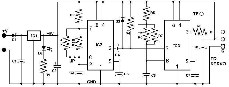
FIGURE 6.
It uses two CMOS 555 timer ICs. The first is an oscillator running at 50 Hz to generate the 20 ms spacing between pulses. The second is a one-shot timer with its output pulse width set by a potentiometer.
I used CMOS because bipolar 555s often have a transient internal short of power to ground when they switch. Such transients generate noise in the form of high current spikes. I used 555s because I had a lot of them. You can also use a 556, which is a dual 555 in a 14-pin DIP.
Figure 7 shows the parts placement on a printed circuit board (PCB).
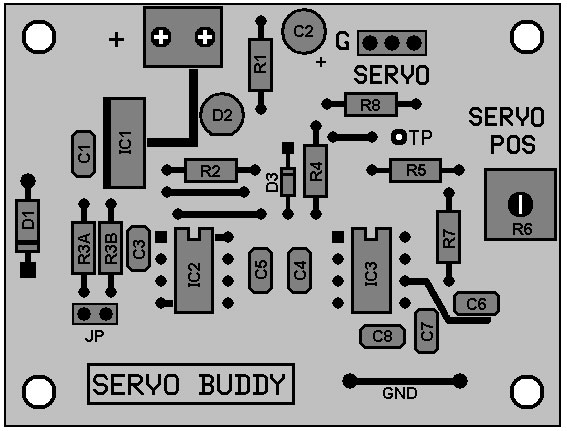
FIGURE 7.
Figure 8 is a photograph of the finished unit.
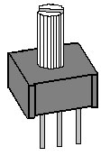
FIGURE 8.
Note the loop of wire along the bottom edge. It’s soldered to ground as a place to attach the ground lead of an oscilloscope or voltmeter.
Circuit Operation
The board is designed to be powered by an unregulated DC wall-wart supply; a 9V @ 1A unit should do the job. Power is connected to a two-position terminal block, and D1 protects against reverse polarity.
An LM7805 regulates the supply down to five volts and is hefty enough to handle one amp slugs of current. C2 is a 100 µF cap, also to handle high current draw. The servo connector attaches to a three-pin header on the board edge.
The oscillation frequency of IC2 is set by C3, R2, R3A, and R3B. R3A and R3B are connected by a removable jumper (JP). With the JP out, IC2 runs at 50 Hz for analog servos. With JP in, IC2 runs at 250 Hz for digital servos. Digital servos will work at 50 Hz, but having the higher
frequency allows them to be tested with a typical input signal.
Using 1% resistors for R2 and R3B, the exact frequency depends on the tolerance of C3. Monolithic ceramics can vary ±20% depending on temperature so either purchase a higher tolerance X7R or temperature compensating NPO or COG types.
Since the output of IC2 is a pulse train, components C4, D3, and R4 form a differentiator to get the negative-going edge required to trigger IC3 in one-shot mode. The output of IC3 goes to the three-pin header, so R8 is there in case the signal pin gets shorted to ground or +5V. The output pulse width of IC3 is set by R5, R6, R7, and C6. R6 is a single-turn pot with a shaft for easy adjustment (see Figure 9).
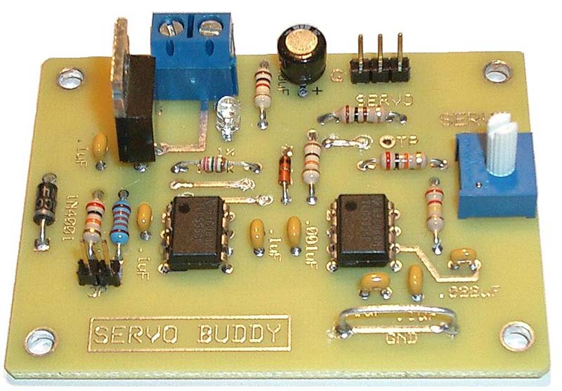
FIGURE 9.
The pot is a no-name brand I bought from Electronix Express. It’s similar to a Bourns type 3386T.
If you need more precise control of servo position, use a multi-turn pot. R5 in series with the pot and R7 across the pot allow you to set the minimum and maximum pulse widths. The values used here give a range of 0.8 to 2.5 ms. The pulse width can be observed at test point TP.
Construction
Construction is straightforward. You will need a breakaway (“snappable”) type male header with at least five pins. For the jumper JP, you need two pins and for the servo connector you need three pins. Such header strips are available from distributors such as Jameco, Electronix Express, and others.
The circuit is simple enough to build on a pre-drilled proto board like the RadioShack 276-150. SV
Parts List
| ITEM | DESCRIPTION |
| R1 | 1K, 1/4W, 5% |
| R2 | 22.0K, 1/4W, 1% |
| R3A | 20K, 1/4W, 5% |
| R3B | 133K, 1/4W, 1% |
| R4 | 10K, 1/4W, 5% |
| R5 | 33K, 1/4W, 5% |
| R6 | 100K pot (see text) |
| R7 | 220K, 1/4W, 5% |
| R8 | 100 W, 1/4W, 5% |
| IC1 | LM7805 |
| IC2,IC3 | LMC555 |
| C1 | 0.1 µF, 50V monolithic |
| C2 | 100 µF, 10V electrolytic |
| C3 | 0.1 µF, 50V monolithic |
| C4 | 0.001 µF, 50V monolithic |
| C5 | 0.1 µF, 50V monolithic |
| C6 | 0.022 µF, 50V monolithic |
| C7 | 0.1 µF, 50V monolithic |
| C8 | 0.1 µF, 50V monolithic |
| D1 | 1N4001 |
| D2 | Green LED |
| D3 | 1N914 |
Miscellaneous Parts
- PCB or proto board
- Removable jumper
- Male header strip on .100 inch centers, break-away type
- Two-position terminal block
A complete kit for this project can be purchased through the SERVO Magazine Webstore at www.servomagazine.com.
Article Comments