The ROBOEAR
By Brian Beard View In Digital Edition
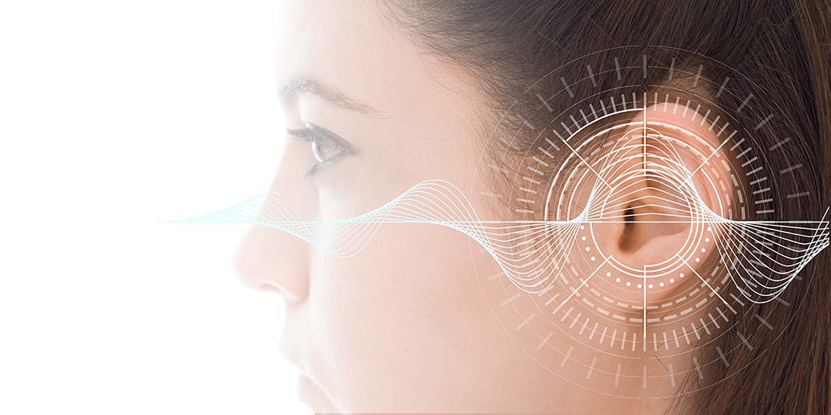
Sound Direction Detection
When I started the ROBOEAR project, I was thinking about the sensors robots use and how they compared with human senses. Humans interact with the world primarily through vision and hearing. Robot “vision” can range from line sensors to video cameras. Robot “hearing” is mostly ultrasonic ranging. However, human hearing provides us with both range and directional cues.
So, I decided to see if I could design a simple system that would detect the direction a sound came from. How difficult could it be? As it turns out, it’s not that easy, and I handicapped myself by using an eight-bit microcontroller. Despite that, the ROBOEAR system works surprisingly well and can also function as the data acquisition front-end for a more powerful processor.
Human Hearing
In psychoacoustics, the ability to determine the direction and distance of a sound source is called localization. The distance to a sound source is normally judged by the amplitude of the sound based on our past experiences. If we hear a car horn, we can make a good guess about how close it is. If we don’t know what we’re hearing, then judging the distance can be difficult.
There are two classic methods used to describe how we determine the direction to a sound source. Phase difference predominates at low frequencies and amplitude difference at high frequencies; at middle frequencies (around 1,500 Hz), neither works particularly well.
Differences in amplitude are more effective at higher frequencies because there is more shadowing effect from the head and the amplitude difference between the ears is more pronounced. Differences in phase are more effective at low frequencies because sound wavelengths are long compared to the size of the head and diffraction allows the sound to bend around the far side of the head.
The speed of sound in air is important because it determines the lag time between microphones. Temperature is the primary factor affecting the speed of sound in air; to a much lesser extent, it’s also affected by pressure, humidity, and even frequency. The speed of sound in air can be approximated by the formula:
Cs = 331.3 + (0.606)*T
Where: Cs = Speed of sound in air in meters per second
T = Air temperature in degrees centigrade
The ROBOEAR uses the approximate speed of sound for sea level at 20°C or 68°F. The error in cross-correlation bearing angles due to this approximation is less than two degrees from 10-30°C (50-86°F).
Cross-Correlation
A common signal processing method to look at phase differences of noisy signals is cross-correlation. Cross-correlation is the comparison of two different time series to detect if there’s a correlation between their peaks and valleys. Simply put, one signal is time shifted with respect to the other and the correlation is measured at each time shift.
The mathematical expression of the cross-correlation function is:
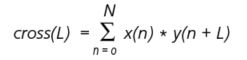
For each time shift — called a lag (L) — the values of the first signal (x) are multiplied by the time shifted values of the second signal (y) and the N product terms are added. The lag step-size is determined by the sample rate; for example, if the signals are sampled at 20 kHz, lag values would change in increments of 50 microseconds.
Consider Figure 1.
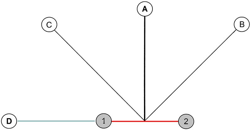
Figure 1. Sound sources relation to microphone baseline.
The baseline between two microphones is shown in red. Sound from A will arrive at mic1 and mic2 at the same time, so the maximum cross-correlation value will be at zero lag. Sound from B will arrive at mic1 last; in this case, the sampled values from mic1 would have to be shifted backward in time (-time) to line up with the sampled values from mic2. So, the maximum cross-correlation value would be at a negative lag.
Conversely for C, the values from mic1 would have to be shifted forward in time (+time) to line up with the signal from mic2, so the maximum cross-correlation value would be at a positive lag. Any source to the left of A will have the maximum cross-correlation value at a positive lag. Because D is on the extension of the baseline (green), this produces the greatest time difference — the maximum lag — between the two microphones. If the distance between the microphones is 10 cm and the speed of sound is 34,320 cm/sec, then it will take 291 μs for the sound to travel from mic1 to mic2. If the signals are sampled at 20 kHz, the maximum cross-correlation would probably occur at a lag of +6 because (291 μs / 50 μs) = 5.8.
However, there’s a problem with the simple diagram in Figure 1. What if A was on the other side of the baseline? Could we tell this from the sampled values at mic1 and mic2? The answer is no. We could not tell which side of the baseline the sound came from; the solution is ambiguous.
There is always a second potential solution as shown in Figure 2. That’s why the ROBOEAR has three microphones and three baselines which yield three ambiguous solutions from which we are usually able to produce one unique solution.
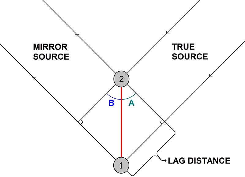
Figure 2. The cross-correlation “mirror” ambiguity problem.
The time difference between sounds arriving at mic2 and mic1 is the same for sources on different sides of the baseline if they are at equal angles from the baseline, as shown by angles A and B in Figure 2. So, how do we determine angle A? Where the lag distance equals the lag time (in multiples of the sample period) times the speed of sound. The angle A is the arcsine of this ratio.
For example, if the maximum cross-correlation occurs at L = 4, the Lag distance is 4*(50 μs)*(34,320 cm/sec ) = 6.86 cm. If we assume the same 10 cm baseline, then the angle A is the arcsine of 6.86/10 or 43.3 degrees. This illustrates how we can use phase or time difference to determine the bearing angle to a sound source.
Amplitude Differences
As mentioned above, differences in amplitude are more effective in determining direction at higher frequencies because there’s more shadowing effect from the head producing a more pronounced amplitude difference between the ears. The ROBOEAR doesn’t have a head and it has three ears (microphones) instead of two. So, the way the ROBOEAR uses amplitude is to consider the amplitude of the samples from each microphone as a vector from the origin to the microphone. Figure 3 shows the geometry.
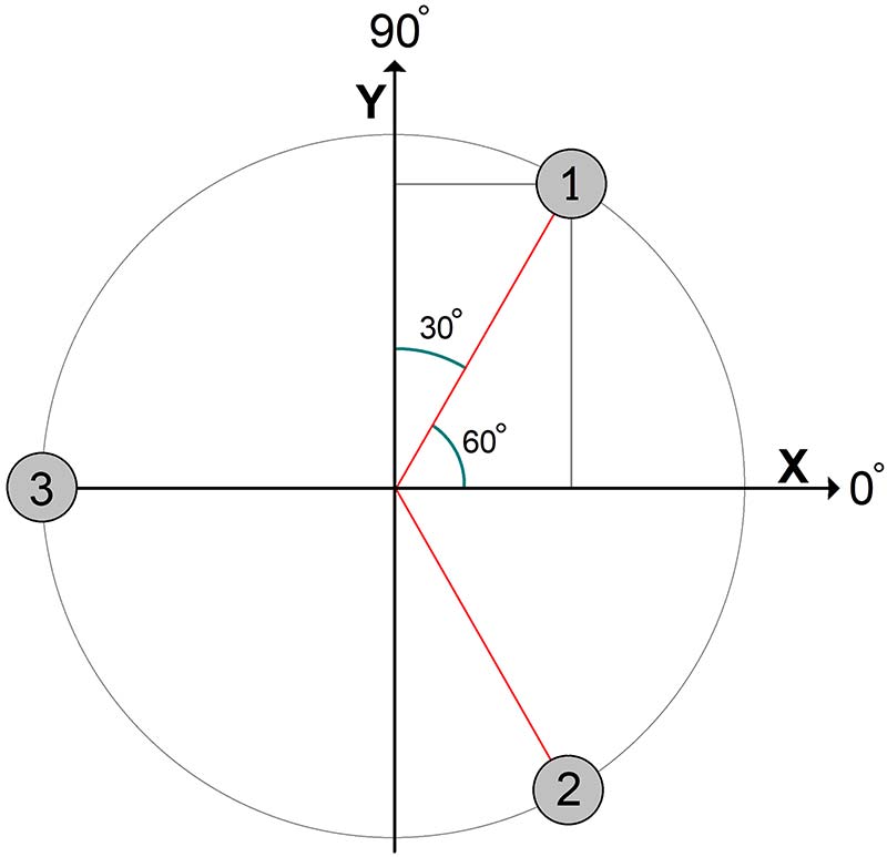
Figure 3. The geometric relationships used to calculate the amplitude bearing.
The amplitude of the signal from each microphone is the maximum value minus the minimum value in a 127 sample set.
Let:
| h1 = the amplitude of the samples from mic1 |
| R1x = the X component of the vector from the origin in the direction of mic1 |
| R1y = the Y component of the vector from the origin in the direction of mic1 |
and similar definitions for mic2 and mic3.
Then:
| R1x = cos(60°)*h1 = 0.5*h1 | R1y = sin(60°)*h1 = 0.866*h1 |
| R2x = cos(-60°)*h2 = 0.5*h2 | R2y = sin(-60°)*h1 = -0.866*h2 |
| R3x = -h3 | R3y = 0 |
The vector sum (Rs) = Rsx + Rsy = (R1x + R2x R3x) + (R1y + R2y) and the bearing angle is the arctan of Rsy/Rsx. Obviously, these calculations will only work if the samples have a reasonable amplitude and there is some difference between channels. Otherwise, the results will be noisy.
Consider the following example:
| h1 = 150 | h2 = 120 | h3 = 90 | |
| R1x = 75 | R2x = 60 | R3x = -90 | Rsx = 45 |
| R1y = 130 | R2y = -104 | R3y = 0 | Rsy = 26 |
| arctan(Rsy/Rsy) = arctan(26/45) = arctan(0.577) = 30° | |||
Practical Problems
This theory is all very nice, but there are a lot of practical problems with trying to replicate the human ability to localize sound. Several problems affect both phase and amplitude processing. Of course, noise is always a problem in signal processing, and noise can come from many sources.
There is noise from sources you don’t want to localize. There is noise from vibrations (such as robot motion) that affects all three microphones simultaneously. There are echoes from nearby walls, interior corners, and ceilings; echoes can be thought of as acoustic multipath.
The ROBOEAR microphones are laid out in a horizontal plane and the theory assumes a sound source in the same plane. If the sound comes from more than 45° above or below the microphones, the accuracy drops off rapidly.
Doing cross-correlation on an eight-bit microcontroller has its own set of problems. The most obvious is memory limitations. I originally thought I could work around that by using a zero-crossing detector (a one-bit ADC; analog-to-digital converter) and doing all the multiplies needed to compute cross-correlation functions as exclusive-ORs.
Theoretically, it should work (I have the simulations to prove it!), but analog noise, differences in op-amp and comparator input offset voltages, and comparator response time necessitated such a high sampling rate that I was still memory limited.
The ROBOEAR processes eight-bit ADC data sampled at 20 kHz. The packed raw data uses 508 bytes of RAM. The 127 unpacked data bytes from each channel are stored in three 128-byte buffers. That uses 892 bytes of the PIC16F1847’s 1,024 bytes of RAM, leaving only 132 bytes for variables and 24-bit math registers.
For amplitude difference processing, the major problem is that there usually isn’t much amplitude difference between the channels. Sound pressure drops off with the square of distance. This means the sound source must be close to the ROBOEAR microphones in order for there to be an appreciable difference in sound pressure over the few centimeters between microphones.
ROBOEAR Hardware
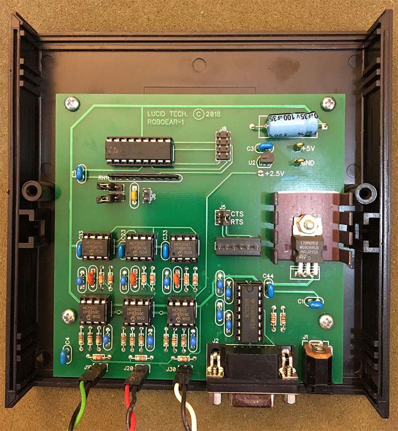
Photo 1. The assembled ROBOEAR-1 circuit board.
Photo 1 shows the ROBOEAR circuit board and Schematic 1 shows the power supply circuitry. The ROBOEAR circuit board is set up for an external 9 VDC power supply. All ROBOEAR circuitry runs on +5V, which is provided by a 78M05 regulator. A heatsink is not really needed as the ROBOEAR draws less than 100 mA. A TLE2426 rail-splitter in a TO-92 package provides a 2.5 VDC virtual ground for the single supply op-amps used in the analog circuitry.
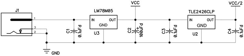
Schematic 1. ROBOEAR power supply circuitry.
The PIC16F1847 microcontroller is U1 in Schematic 2. The PIC has 14 Kbytes of Flash program memory, 1 Kbyte of data memory (RAM), a universal asynchronous receiver transmitter (UART), a synchronous serial port (SPI), and a 10-bit ADC. The PIC’s internal oscillator is programmed to operate at 16 MHz.
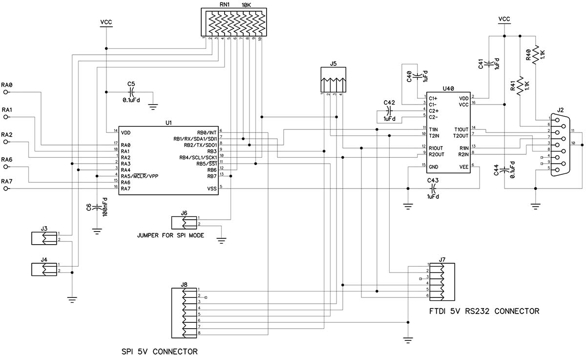
Schematic 2. ROBOEAR microcontroller, RS-232, and option jumpers.
U40 is a MAX232 five volt powered RS-232 interface with two drivers and two receivers. One receiver/driver pair handles RS-232 data to/from the ROBOEAR. The other receiver/driver pair handles the control lines RTS and CTS.
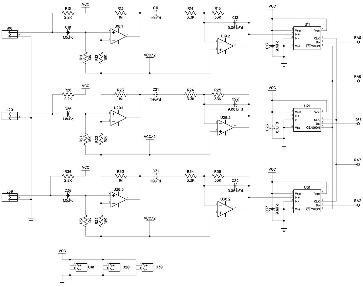
If you have an FTDI TTL-232R-5V USB-to-serial adapter, you can connect it at J7, which eliminates the need for the MAX232. The ROBOEAR supports baud rates from 9600 to 76800. Typically, the ROBOEAR receives RTS and sends it back to the host as CTS, but flow control can be used by changing the jumpers on J5. The ROBOEAR has three analog channels. Each channel has a microphone input and two op-amps packaged in a single MCP602. The analog circuitry is shown in Schematic 3.
Schematic 3. ROBOEAR analog input channels.
The ROBOEAR is designed to work with most inexpensive electret microphones that have an output impedance of approximately 2,200 ohms. The microphone is AC coupled to the first op-amp that is configured for a positive gain of 100. The output of the first op-amp is AC coupled to the second op-amp that is configured for a negative gain of 10 and a low-pass roll-off of 4,800 Hz.
The final component in each channel is the MCP3001 ADC) The MCP3001 is a successive approximation 10-bit ADC with onboard sample and hold circuitry. Communication with the ADC is done using a simple serial interface compatible with the SPI protocol. Although the PIC has an internal multi-input ADC, it’s not suitable for this application. The PIC has one ADC with an analog multiplexer on the input; thus, it does sequential conversions.
Because cross-correlation depends on knowing the value of multiple inputs at the same points in time, simultaneous sampling is required. This is accomplished by connecting the clock and chip-select inputs of all three ADCs in parallel. The serial data outputs go to three inputs on the same PIC input port. The serial output from the ADCs is stored by the PIC in packed format and unpacked into individual channels after all the samples have been acquired.
Because the MCP3001 is a serial successive approximation converter, the conversion can be halted before reaching 10 bits. Because the ROBOEAR has eight-bit RAM, it routinely uses eight-bit conversions; 10-bit conversions are available but must be analyzed externally.
Three electret microphones connect to the ROBOEAR at connectors J10, J20, and J30. The connecting wires must be long enough to arrange the microphones in the required pattern. The microphones need to be arranged in the correct order, in the form of an equilateral triangle 10 centimeters on a side. This can also be thought of as mounting them 120 degrees apart on a circle with a radius of 5.7 cm.
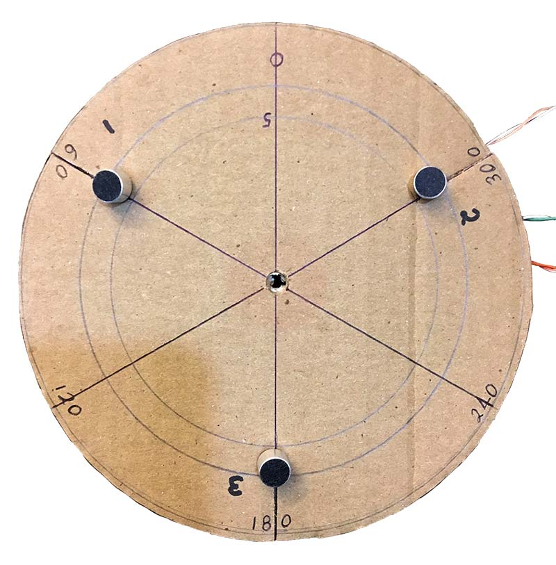
Photo 2. The prototype microphone array.
The order of the microphones (numbered according to the analog channel to which they are wired) is critical to determining the direction to a sound source. Figure 4 shows how the detected direction corresponds to this proper arrangement. The plane of the microphones should be parallel to the ground.
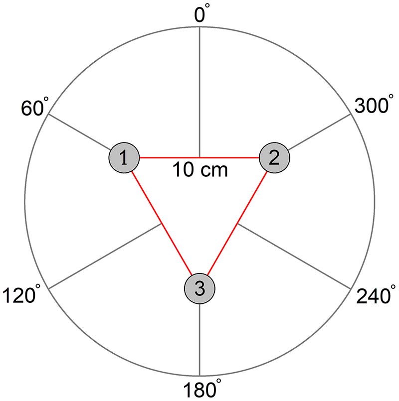
Figure 4. The bearing angle circle in relation to the microphone array.
ROBOEAR Software
When the ROBOEAR is powered up, it reads jumper J6 to determine whether to communicate with the host via UART or SPI. The ROBOEAR boots up in “human” mode and displays the menu that follows.
In human mode, when the host sends a command the ROBOEAR echoes the command. If the command is not valid, then a NAK is returned and the menu is sent again. If the command is valid, an ACK is returned, the command is executed, and the menu is sent again.
ROBOEAR, firmware 1.06
[E] Acquire one set of 8-bit data
[T] Acquire one set of 10-bit data
[R] Send raw data in CSV format
[P] Acquire and process one set of 8-bit data
[S] Send processing statistics
[B] Send bearing angles
[M] Set minimum channel range
[H] Use Hex values for raw data
[D] Use Decimal values for raw data
[A] Use BAM format for bearings
[G] Use decimal degrees format for bearings
[C] Computer control mode, ESCape to exit
?
If the host is controlling the ROBOEAR without human intervention, it can put the ROBOEAR in “computer control” mode by waiting until it sees a “?” then sending a “C” to the ROBOEAR. In computer control mode, commands are not echoed and the menu is not sent between commands.
The E, T, and R commands are useful in computer control mode when the host computer will be processing the raw audio data from the three channels. E and T will acquire a data set; that is 127 samples at 20 kHz from all three channels. R will send the unprocessed raw data to the host in the numeric format specified by the H or D command. Raw data is sent as 127 lines with each line containing three comma-separated values: Channel1,Channel2,Channel3.
The H, D, A, and G commands are used to set the numeric format to report raw data and computed bearing angles. At power-up, all formats default to decimal. Decimal data is always sent with leading zeros suppressed. Hexadecimal data is sent as two characters for eight-bit data and three characters for 10-bit data.
Internally, the ROBOEAR stores all raw data values from the channels in binary, so it takes less time to convert them to ASCII-hexadecimal than it does to ASCII-decimal representations. Thus, transfer of raw data in ASCII-hex format may be the best choice if time is critical.
The ROBOEAR stores bearing angles in eight-bit Binary Angle Measure (BAM) format. In BAM, the MSB represents 180 degrees and each lesser bit half of the higher bit. BAM values are sent in hexadecimal format. Reporting the bearings in decimal format involves multiplying, dividing, and converting binary to BDC. So, if speed is an issue, BAM format will be quicker.
Binary Angle Measure
Binary Angle Measure (BAM) works as follows: Consider the MSB of an n-bit word to be 180 degrees with each less significant bit to be half. For example, an eight-bit BAM would have the following bit weights:
bit 7 = 180 degrees
bit 6 = 90 degrees
bit 5 = 45 degrees
bit 4 = 22.5 degrees
bit 3 = 11.25 degrees
bit 2 = 5.625 degrees
bit 1 = 2.812 degrees
bit 0 = 1.406 degrees
The accuracy of a BAM can be increased by increasing the word size. For a 12-bit BAM, the LSB represents 0.0879 degrees; for a 16-bit BAM, the LSB represents 0.0055 degrees.
Each n-bit BAM has a maximum value of 360 LSB. BAM can be added and subtracted together and multiplied and divided by constants as if they were unsigned integers, then converted at the last stage to produce floating-point results.
It’s easy to show that the overflow condition for BAM numbers presents no problem as the angle simply wraps around to zero.
The M command is used to set the minimum dynamic range (amplitude) required for each channel before the P command will use the data to calculate a bearing. This is the minimum used in step 4 of the flowchart that follows for the P command. The default minimum is 31 out of the maximum eight-bit amplitude of 255. The M command has no effect on the E or T commands.
The P, S, and B commands are useful in human and computer control modes. The P command acquires data until all the channels meet the minimum amplitude set by the M command. Then, it processes the data and calculates bearings by the amplitude and cross-correlation methods; refer to the flowchart. The S command reports the average and amplitude of each channel and the B command reports the bearing angles in the format specified by the A or G command.
P Command Flowchart:
1. Acquire packed raw data.
2. Unpack the data into the three channel buffers.
3. Compute the average and amplitude for each buffer.
4. If any channel’s amplitude is < the minimum goto 1
5. Compute the amplitude bearing tangent.
a. Look up the amplitude bearing angle.
6. Convert the channel buffers to signed binary values.
7. Compute the cross-correlation function for a range of lag values for each baseline.
a. Find the maximum cross-correlation value and matching lag value for each baseline.
b. Look up the bearing angle for the three lag values.
8. Signal the host data is ready.
The processing power required for all this is a severe challenge for an eight-bit microcontroller. For example, calculating the cross-correlation values involves three baselines, 13 lags per baseline (-6 to +6), and 115 points per lag (the fully overlapped portion of each channel’s 127 data points). That means it takes 4,485 eight-bit multiplications and 24-bit additions just to do the cross-correlation. Despite the processing demand, if the amplitudes are okay in step 4, the ROBOEAR can repeat the process at least four times a second.
Cross-correlation works best with long time series; this produces very high and narrow peaks when the time series line up. One of the consequences of the limited memory available is the relatively short (127 samples) time series from the three channels. Because of these short time series, the cross-correlation functions produce broad peaks.
Figure 5 is a real example from the ROBOEAR.
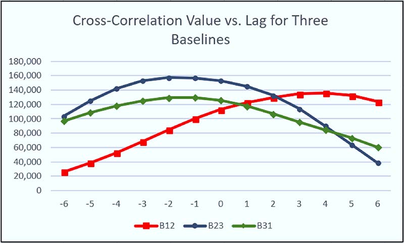
Figure 5. An example of cross-correlation values versus lag for the three microphone baselines.
Because the peaks are so flat, the position of the maximum can easily shift ±1 lag from one data set to the next, solely due to noise. This limits the accuracy of the computed bearings from each baseline. So, even though the ROBOEAR could compute bearings with a lot of precision, they would not be very accurate. Therefore, I decided to have the ROBOEAR report bearings as sectors.
Using sectors simplifies the process of reducing the cross-correlation ambiguities to a single solution. In fact, the only thing we need to know is if the maximum cross-correlation occurred at a positive lag, zero, or a negative lag. Figure 6 shows how this works.
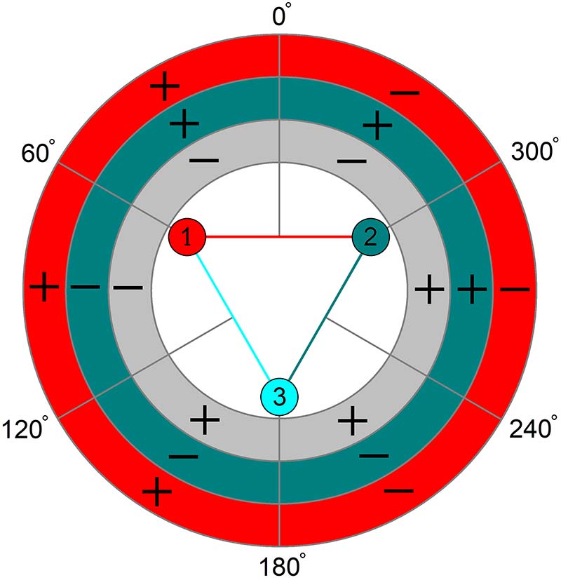
Figure 6. Bearing sector map color coded by microphone baseline.
For example, consider a source at 90°. The maximum cross-correlation for any source between 0° and 180° should be found at a positive lag for baseline 1-2 (color coded red). For baseline 2-3 (green), the maximum cross-correlation should be at a negative lag; the same is true for baseline 3-1 (blue). Thus, if the order of the signs of the lags for the three baselines is (+, -, -), then the bearing is in the sector centered at 90°.
So, what happens if maximum cross-correlation for one of the baselines has a lag of zero? A lag of zero means the source is on a line perpendicular to the baseline. For the example above, if the lag for baseline 3-1 was zero, then the order would be (+,-,0) and the solution would be the sector centered at 120°.
There are 12 30° wide sectors; each one is identified by a unique sequence. However, there are more than 12 possible sequences. Suppose the lag sequence was (+,+,+). The source would need to be on the left side of all three baselines — an impossible situation. This kind of situation can happen in the presence of noise and echoes.
When a unique solution is impossible, the bearing angle is returned as 0xFF in BAM or its equivalent decimal value of 358.
The performance of the ROBOEAR in a real world situation depends on so many external factors, it’s impossible to predict. I ran a series of indoor tests using a radio at a distance of 1.5 meters as the sound source. Because of the way the amplitude bearing is calculated, it will always yield a solution.
My results showed a mean error of 28° with a standard deviation of 114° for the amplitude bearing. The cross-correlation bearing gave valid results about 90% of the time, with the valid results having a mean error of 2.6° and a standard deviation of 26°. To me, this implies averaging the last few valid cross-correlation bearings is probably the best way to use the ROBOEAR.
Summary
The ROBOEAR provides a lot of opportunities for experimentation in acoustic localization. You can let the ROBOEAR calculate bearing angles and work out the most reliable way to use them. You can use the ROBOEAR as an analog front end for a more powerful processor.
If you use an external processor to analyze the raw data, you could:
- Change the size (microphone baseline) of the equilateral triangle.
- Change the arrangement of the microphones; for example, a right triangle.
- Experiment with ways to improve the calculation of bearing angle.
However, as long as you use the ROBOEAR’s firmware, you’ll be limited to time series 127 bytes in length sampled at 20 kHz.
The assembly source code for the ROBOEAR is available with the downloads. Feel free to modify it in any way you like, to make the ROBOEAR do anything the hardware is capable of.
It might be possible to modify the code to increase the number of samples per channel, change the sample rate, and — if you’re particularly clever — perhaps even acquire samples in real time. SV

Resources
Texas Instruments
www.ti.com
TLE2426 Datasheet, SLOS098D, rail-splitter, precision virtual ground
MAX323 Datasheet, SLLS047M, dual EIA-232 driver/receiver
Microchip
www.microchip.com
PIC16F184 Datasheet, DS400011453E, enhanced mid-range eight-bit microcontroller
MCP602 Datasheet, DS21314F, dual single-supply op-amp
MCP3001 Datasheet, DS21293C, 10-bit ADC with SPI interface
Explanations of correlation
https://www.youtube.com/watch?v=_r_fDlM0Dx0
https://www.youtube.com/watch?v=L6YJqhbsuFY
https://www.youtube.com/watch?v=RO8s1TrElEw
Speed of sound in air
https://en.wikipedia.org/wiki/Speed_of_sound
Lucid Technologies’ home page
www.lucidtechnologies.info
Parts List
| Qty | Part | Reference |
| 8 | 0.1 µFd, 0.1” LS | C1, C3, C4, C5, C13, C23, C33, C44 |
| 1 | 100 µFd, axial | C2 |
| 1 | 100 nFd, 0.2” LS | C6 |
| 10 | 1.0 µFd, 0.2” LS | C10, C11, C20, C21, C30, C31, C40-C43 |
| 3 | 0.001 µFd, 0.2” LS | C12, C22, C32 |
| 3 | 2.2K, 1/8W, 5% | R10, R20, R30 (red-red-red-gold) |
| 6 | 10K, 1/8W, 5% | R11, R12, R21, R22, R31, R32 (brown-black-orange-gold) |
| 3 | 1M, 1/8W, 5% | R13, R23, R33 (brown-black-green-gold) |
| 3 | 3.3K, 1/8W, 5% | R14, R24, R34 (orange-orange-red-gold) |
| 3 | 33K, 1/8W, 5% | R15, R25, R35 (orange-orange-orange-gold) |
| 2 | 1.1K, 1/8W, 5% | R40, R41 (brown-brown-red-gold) |
| 1 | 10K, 10-pin SIP | RN1 |
| 1 | PIC16F1847 | U1 |
| 1 | TLE2426CLP | U2 |
| 1 | LM78M05 | U3 |
| 3 | MCP602 | U10, U20, U30 |
| 3 | MCP3001 | U11, U21, U31 |
| 1 | MAX232ACPE | U40 |
| 1 | 18-DIP socket | U1 |
| 1 | 16-DIP socket | U40 |
| 6 | 8-DIP socket | U10, U11, U20, U21, U30, U31 |
| 1 | DC power jack | J1 |
| 1 | DB9 female connector | J2 |
| 6 | 2-pin header | J3, J4, J6, J10, J20, J30 |
| 1 | 4-pin header, 2x2 | J5 |
| 1 | 6-pin header, 1x6 | J7 |
| 1 | 8-pin header, 2x4 | J8 |
| 1 | ROBOEAR-1 circuit board | |
| 4 | Self-tapping screws for mounting the printed circuit board in a plastic case | |
| 3 | Jumpers | |
| 3 | Electret microphones | |
Article Comments