SPY-DER: A Speech & Web Controlled Surveillance Spider Robot
By Arijit Das View In Digital Edition
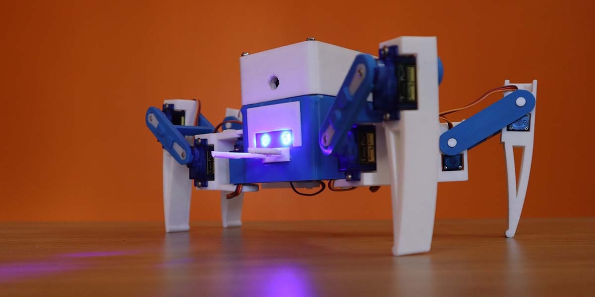
SPY-DER is a surveillance robot. Not just any robot, but one that can walk like a spider and work as a spy using its camera at the same time. Hence, the name SPY-DER.
SPY-DER could be controlled manually using voice commands as well as through a web based control interface. Technologies like hotword or wakeword detection ensure a simple call to its nickname “Bumblebee” will activate its voice command mechanism, where as speech recognition ensures the robot understands the commands.
Along with speech recognition, intent detection provides the ability of giving the same command in different ways, i.e., “wave your hands” or “say hello.” Both commands will make the robot wave its legs. Moreover, one can simply open a particular URL using any browser and access the web based control interface of SPY-DER. The interface contains several functional buttons which could be used to control the robot. Using another URL, a user can watch the live video feed from SPY-DER.
The demo video of this project and its build video are available at https://youtu.be/3edXTxIZ_2U and [url=https://youtu.be/KkZiZggtvIU]https://youtu.be/KkZiZggtvIU[/url].
Build Requirements
To build this project, the following hardware components are required:
- Arduino Nano
- Raspberry Pi Zero W
- Raspberry Pi Camera
- 5V to 3.3V Logic Level Shifter
- Nano 328P Expansion Adapter Breakout Board IO Shield
- SG90 Mini Servo (12 pieces)
- Buck Converter LM2596
- Lithium-Ion Battery (two pieces)
- LEDs
- Jumper Wires
- USB Mic
- OTG Cable
Overall Idea
At first, SPY-DER was a simple Bluetooth-controlled spider robot built using an Arduino Nano which could be controlled using an Android/IOS application. This was cool but not that impressive. Integrating speech recognition, web control, and surveillance was a big challenge.
Implementing all these features onto a single Arduino board was not feasible and demanded a more powerful machine. So, a Raspberry Pi Zero became the new computing device for SPY-DER. All the features could be integrated together using the Raspberry Pi Zero but the whole spider movement control code had to be rewritten in Raspberry Pi.
This can be cumbersome, so the RaspPi was connected to the Nano through serial communication. The Raspberry Pi controls the Arduino which, in turn, controls the spider robot’s movements with just a few simple modifications to the previous code.
All the codes for this project are written in Python for the Raspberry Pi. As for the web based control interface, the webpage was built using HTML, CSS, and jQuery using the Flask framework. The RPi-Cam-Web-Interface (https://elinux.org/RPi-Cam-Web-Interface) is used for live video streaming since the latency is very low.
Modified code of Picovoice (https://picovoice.ai/) is used for speech recognition and hotword detection. As the RAM and processing power is very limited with a RaspPi Zero, the accuracy results using local speech recognition systems weren’t that great, plus the latency was very high.
Building the Robot
Designing and Printing Parts
A few modifications were undertaken on an existing robot design (Figure 1).
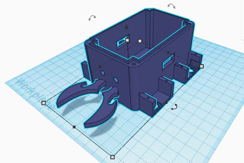
Figure 1: Designing parts.
You can check them out at https://www.thingiverse.com/thing:4815137. The parts were 3D printed using an Ender 3 3D printer (Figure 2).
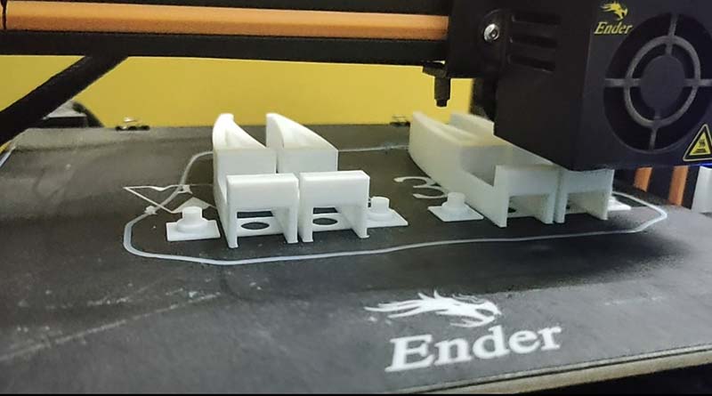
Figure 2: 3D printing parts.
Attaching Servo Motors on the 3D Printed Parts
After 3D printing the parts, SG90 servo motors were attached to them accordingly (Figure 3).
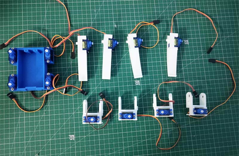
Figure 3: Servomotors attached with the body parts.
Connecting All the Body Parts Together
All the 3D printed parts were assembled together through the servo motors. Take a look at Figure 4 and Figure 5.
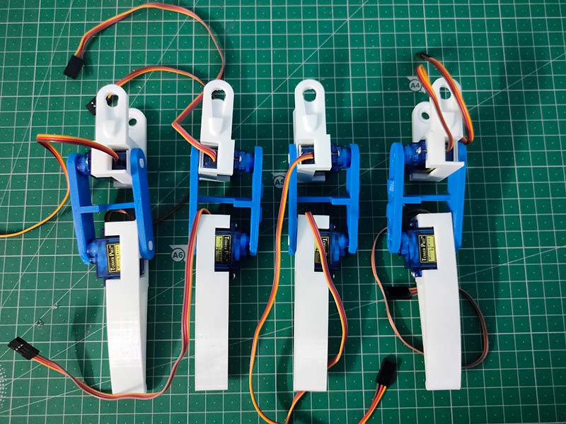
Figure 4: Legs assembled.
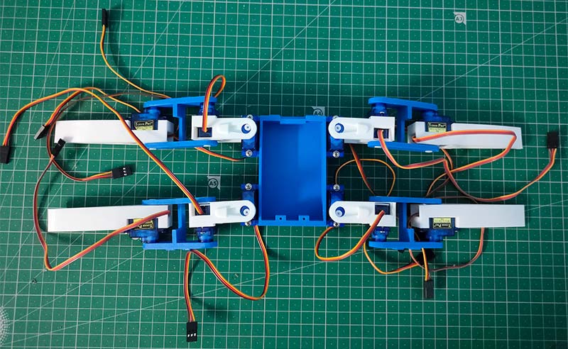
Figure 5: Legs connected with body through servo motors.
Attaching the Battery and Battery Management System
The battery management system and two lithium-ion batteries connected in series were attached to the robot, which provided 7-8 volts (Figure 6 and Figure 7).
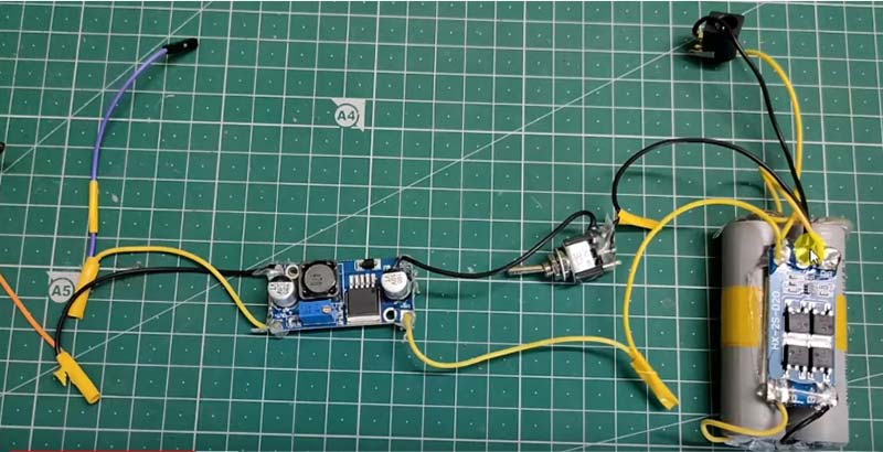
Figure 6: Battery with battery management system (BMS).
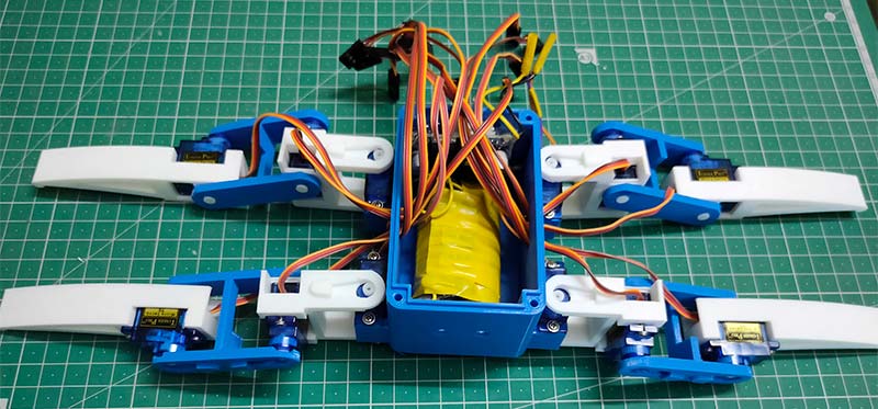
Figure 7: Battery and BMS attached in the body.
An LM2596 buck converter was used to reduce the voltage to five volts to provide power to the Arduino, servo motors, and the RaspPi.
Connecting the Arduino in the Robot
The Arduino Nano is connected to the IO shield along with all the servo motors. Special precaution must be taken while connecting servo motors to their designated positions as per the servo numbering figure and the circuit diagram. Refer to Figures 8, 9, and 10.
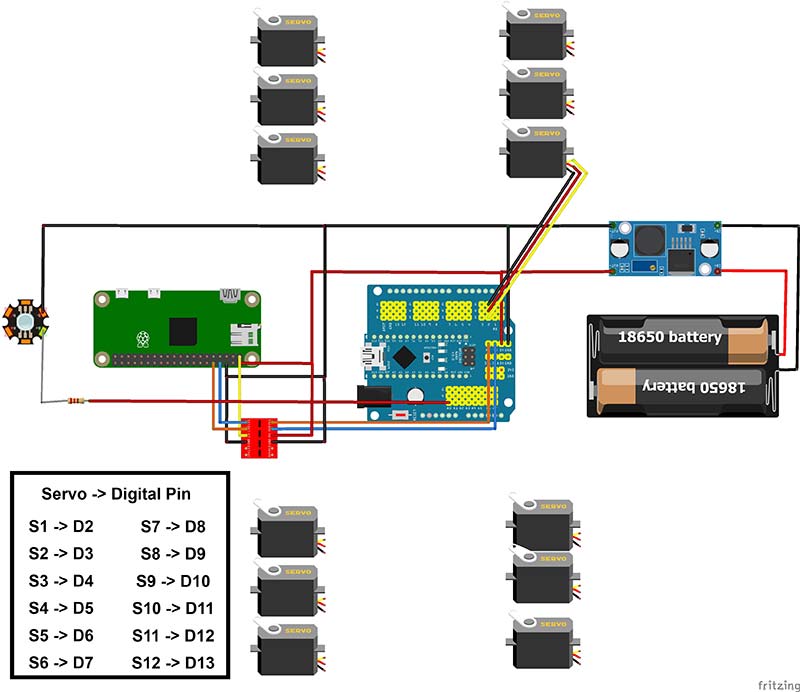
Figure 8: Circuit diagram.
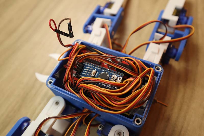
Figure 9: Arduino attached in the body.
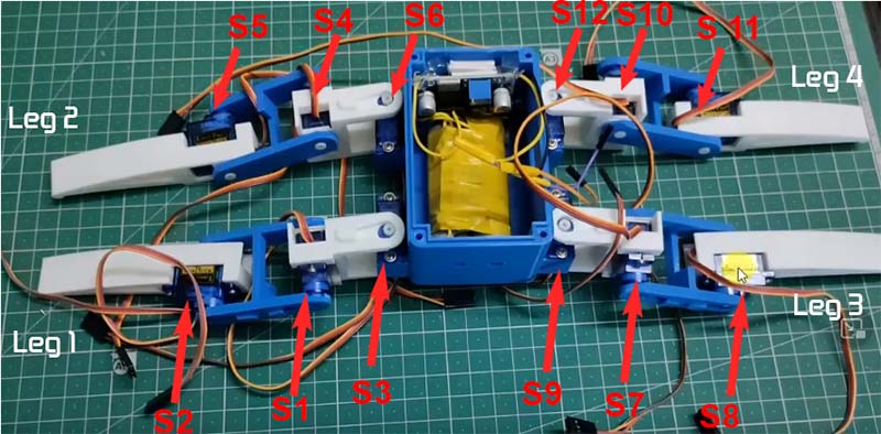
Figure 10: Servomotors numbering.
Uploading Code to the Arduino
The Arduino sketch was uploaded to the Nano and the legs of the robot were calibrated. The code is available in the downloads, as well as at https://github.com/Arijit1080/Spidy-The-Spider-Robot.The program is available in the “Legs” folder.
The code available in folder “Program1” can be used to validate the basic robot movement functions like forward, backward, right, left, etc. Go to https://www.youtube.com/watch?v=fnMmnd9k6q8 to learn more.
Lastly, the final code for the Arduino which will work with the Raspberry Pi (SPY-DER_Arduino.ino) file was uploaded to Arduino. You will find this code in the downloads as well. You can also go to https://github.com/Arijit1080/SPY-DER-A-Speech-and-Web-Controlled-Surveillance-Spider-Robot-using-Raspberry-Pi-and-Arduino.
Raspberry Pi Setup with Mic & Camera
The RaspPi camera, USB mic, and logic level shifter were connected to the Raspberry Pi Zero (Figure 11).
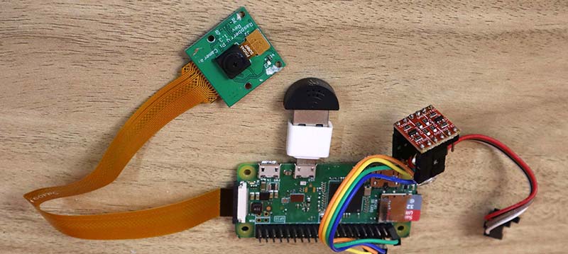
Figure 11: Mic and camera attached with Raspberry Pi.
To learn about serial communication, check out the video at https://www.youtube.com/watch?v=e04br5J4UpQ. To learn how to use the RaspPi camera, go to https://www.youtube.com/watch?v=oo0A_yRrIxQ.
Connecting the Raspberry Pi with the Arduino
The logic level shifter was then attached to the Arduino to connect the Arduino and RaspPi serially (Figure 12).
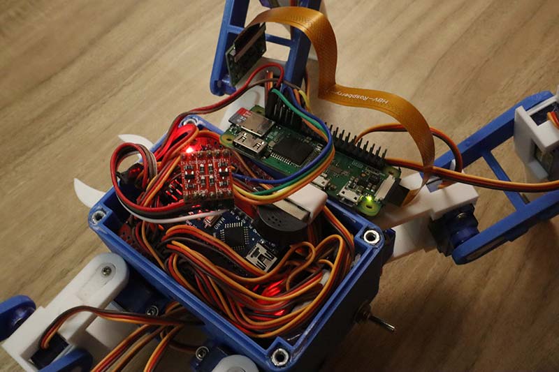
Figure 12: Raspberry Pi connected in the body.
Raspberry Pi Setup
To set up the RaspPi, install all the required libraries and upload the codes available in the downloads. The mic and camera connection are to be tested herein.
Next, we need to clone the PicoVoice repository (in the downloads) and the required changes to that code.
For the web-control part, the required Python and HTML files are available in the downloads as well.
To install RPi-Cam-Interface for the video-streaming part, refer to the video available at https://www.youtube.com/watch?v=yzpqEw1kEGo for assistance.
Training the Speech-to-Intent Model
Next step is to train the Rhino speech-to-intent model (Figure 13) so that for a single task, different commands (i.e., “open your eyes” or “turn on lights”) could be used to make the robot turn on its LEDs.
For this, the Rhino speech-to-intent context model which is a part of PicoVoice must be trained from https://console.picovoice.ai/rhn. The model can then be downloaded and uploaded to the Raspberry Pi.
Figure 13 shows a glimpse of this model.
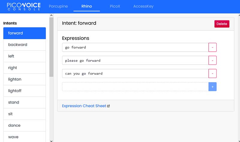
Figure 13: Rhino speech-to-intent context model training.
Finishing the Build
Figure 14 shows all the components connected.
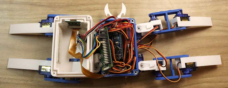
Figure 14: All components connected.
The lid is finally closed after fitting everything inside the body (Figure 15).
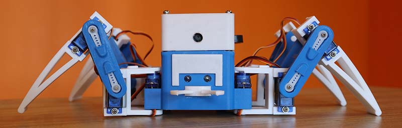
Figure 15: After attaching the lid.
Using the Robot
After the robot is complete, a few commands must be used for the Raspberry Pi to run the robot. To run the web control interface:
cd web_control
python3 web_control.py
To run the speech control system:
cd picovoice
python3 demo/python/picovoice_demo_mic.py
--keyword_path resources/porcupine/resources/keyword_files/raspberry-pi/bumblebee_raspberry-pi.ppn
--context_path your_rhino_model
Refer to the video at https://www.youtube.com/watch?v=KkZiZggtvIU if you need help on how to run the codes properly. To access the web-control interface from any browser (Figure 16), use Raspberry_pi_ip:5010.
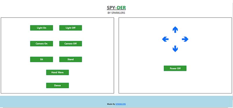
Figure 16: Web control interface.
For live video streaming (Figure 17), use Raspberry_pi_ip:80.
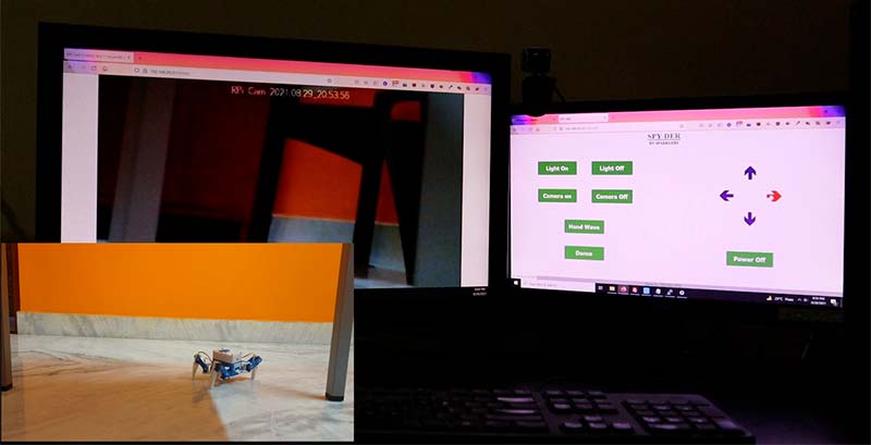
Figure 17: Live surveillance.
Conclusion and Improvements
That wraps up my build for this project. Of course, there are many different ways that can be used to complete a project like this. Modifications like a local speech recognition system, using image processing, and AI based features for the camera could be done for this project as there is plenty of room for future improvements. SV
References
Demo Video of this Project
https://youtu.be/3edXTxIZ_2U
Build/Tutorial Video
https://youtu.be/KkZiZggtvIU
RPi-Cam-Web-Interface
https://elinux.org/RPi-Cam-Web-Interface
PicoVoice
https://picovoice.ai/
3D Files
https://www.thingiverse.com/thing:4815137
Code for this Project
https://github.com/Arijit1080/SPY-DER-A-Speech-and-Web-Controlled-Surveillance-Spider-Robot-using-Raspberry-Pi-and-Arduino
Basic Spider Robot Build Video
https://youtu.be/fnMmnd9k6q8
Basic Spider Robot Code
https://github.com/Arijit1080/Spidy-The-Spider-Robot
PicoVoice Github Repo
https://github.com/Picovoice/picovoice
Rhino Speech-to-Intent Model
https://console.picovoice.ai/rhn
Raspberry Pi and Arduino Serial Communication Video
https://youtu.be/e04br5J4UpQ
Using the Camera with the Raspberry Pi Video
https://youtu.be/oo0A_yRrIxQ
Article Comments