Using Stepper Motors for Wheeled Robot Propulsion
By Theron Wierenga View In Digital Edition
A few years back, I became interested in attempting to propel a wheeled robot using stepper motors. This is not the usual method for propelling a robot. A more typical approach is to use two traditional DC motors. Individual differences in the two DC motors are then accommodated by optical feedback that provides data which can be used to match the speed of the two motors.
The characteristics of stepper motors that appealed to me were their ability to precisely turn a wheel at a calculated distance and their ability to brake. Stepper motors are not a panacea for robot propulsion. They are heavier, use more power, and have far less torque than traditional DC motors. In addition, they cannot be operated at great rotational speeds and the faster they run, the less torque they have. One needs to be careful in selecting a stepping motor. It has to have enough holding torque for robot propulsion. In general, you will find the weight and size of a stepper motor needed to drive a given size robot larger than traditional DC motors.
Stepper motors come in two basic types: bipolar and unipolar. Bipolar stepper motors need drivers that can alternately supply current in both directions through the motor’s coils, while unipolar stepper motors always run the current in one direction through the coils — which also means a simpler driver circuit. We will only be discussing unipolar stepper motors in this article.
Stepping motors are a very different animal compared to traditional DC motors. A good overview of stepper motors can be found at http://en.wikipedia.org/wiki/Stepper_motor. In addition, I noticed several universities are using an early copy of a Thomson/Airpax catalog which contains a very good review of stepping motors. A couple of URLs for this are www.ece.mtu.edu/labs/EElabs/EE2304/EE2304_website_2008/Stepper%20Motor%20Resources/Airpax_Catalog_Idx.pdf and www.ece.ualberta.ca/~ee401/parts/data/AirpaxCatalog.pdf. There is also a brief version at www.mpja.com/download/18304ms.pdf.
The Hardware
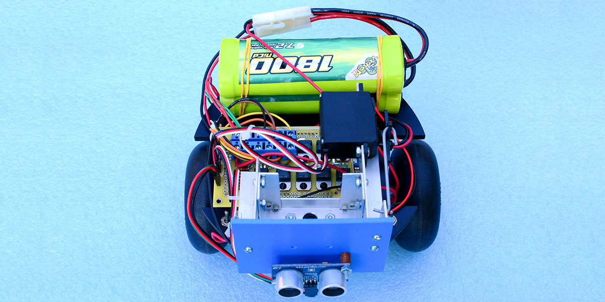
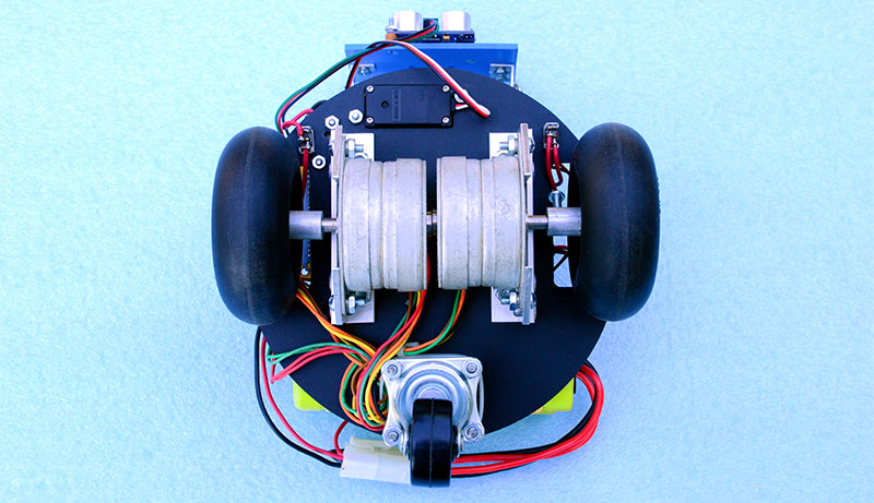
I constructed two robots using stepper motor propulsion. I used seven inch round, 1/4 inch thick expanded PVC for the base of my small model. (Included in the download material at the article link are some basic drawings of the seven inch robot.) For this small robot, I used two Airpax MA82818 stepper motors driving 3.5 inch wheels. These stepper motors can still be found surplus and eBay sometimes has them. They are rated at 12 volts and 47.5 ohms per coil, so at the rated voltage it will draw 252 milliamps.
Another choice could have been a Mercury Motor 57BYGH213 which is rated at 6.2 volts and one amp with 9 kilogram centimeters of torque. I have used this Mercury motor in a barn door camera mount which rotates a camera at the same speed as the Earth revolves, allowing for photographing the stars. The holding torque (in general, its strength) is somewhat greater than the Airpax model.
The larger robot used two 14 inch round pieces of 1/4 inch thick expanded PVC for its body. I used larger Bodine stepper motors rated at 100 oz/in holding torque. These motors are 2.25 inches in diameter and 3.5 inches long, and are attached to six inch diameter lawnmower replacement wheels.
I previously used PICAXE and BASIC Stamp microcontrollers for these robots, but am now updating them with Arduino boards. This article will describe the use of an Arduino Mega 2560 board and the Airpax MA82818 stepper motors mounted on the seven inch robot.
The first decision to make is how to drive the stepper motors. The Arduino cannot drive the steppers directly. You must either use one of the stepper motor driver ICs available, or simply use power transistors or MOSFETs for driving the stepper motor directly. Two stepper motor IC drivers I have used are the UCN5804B which is rated at 500 milliamps, and the SLA7062M rated at three amps. These circuits are very convenient in that you simply connect the stepper motor to them and send control signals to a timing clock, forward/reverse, speed, etc. On the other hand, we can simply drive a stepper motor with four power transistors or MOSFETs, along with four diodes to protect the transistors from the back inductive kick of the motor windings. I used the simple four transistor method with BUZ11A MOSFETs and compensated by writing a software package for the Arduino that does the necessary controlling.
The advantage of using the power transistors is that the circuit can be used for stepper motors requiring higher current. In addition, the exercise of writing the necessary software will help to better understand the operation of the motors.
It is not unusual to run stepper motors higher than their ratings — within reason. Not all the windings have current going through them at the same time, so the problem of heat dissipation when running at a slightly higher voltage is usually not a problem. I used two 7.2 volt NiCad batteries in series to drive the stepper motors, and tapped off 7.2 volts from one to power the Arduino board. Figure 1 is the schematic of the dual stepper motor driver.
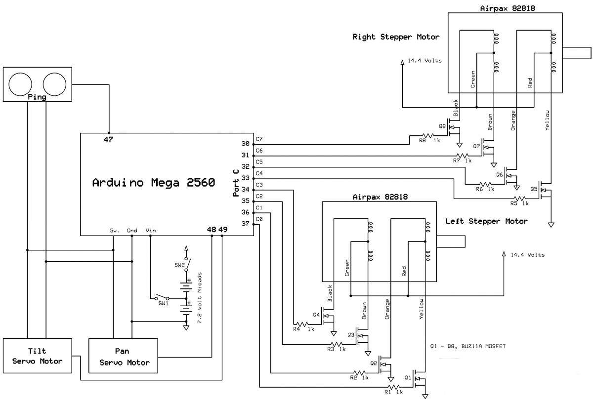
FIGURE 1. Schematic of the stepper motor driver.
In addition to the Arduino driving the stepper motor, the circuit also interfaces with two servo motors which operate a pan-and-tilt platform which has a PING))) sonar device mounted to it. Because of the large number of connections, I designed a shield — a board that plugs into the Arduino Mega 2560 — which mounts all the driver circuitry. My choice of printed circuit board (PCB) manufacturers was ExpressPCB. They provide easy-to-use software and have a special service called Miniboard that provides three boards — 3.8 x 2.5 inches — for just under $65, which is just the right size for a custom Arduino shield.
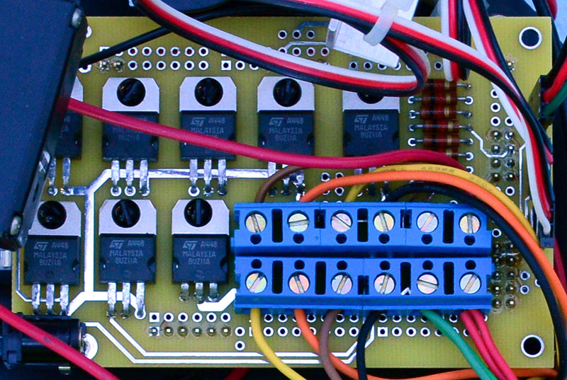
FIGURE 2. Close-up of the printed circuit board that mounts the driver circuitry; the Arduino Mega 2560 is underneath.
The board mounts the MOSFETs, the gate resistors, reset switch, terminal blocks for easy connect/disconnect of the stepper motors, and six three-pin headers for easy plug-ins for the servo motors and PING))) sonar. The ExpressPCB file is included at the article link.
Along with the voltage and current ratings of a given stepper motor, the step angle in degrees is also provided. In the case of the Airpax MA82818, it is 7.5 degrees. So, the shaft on the stepper motor will turn 7.5 degrees for every set of step commands sent to it. Dividing 360 degrees for a full turn of the shaft by 7.5, there are 48 steps for each full rotation of the shaft. So, if the shaft of the stepper motor is connected directly to a wheel, one full rotation will move the robot ahead the same distance as the circumference of the wheel.
The wheels used are 3-1/2 inch smooth model airplane versions. I chose these because they were the right size. A better choice would have been wheels with some tread on them as the smooth ones tend to slip a little — especially on carpet. I constructed simple wheel couplings from 1/2 inch aluminum rod, then placed a threaded hole in the end to attach the wheel, and a threaded hole in the side for a set screw to attach to the stepper motor shaft.
The Software
So, how do you get a stepper motor to move one step? Take a look at Table 1. There are four coils in the stepper motor and current is selectively passed through specific coils in a pre-determined pattern which is provided on the stepper motor’s datasheet. Each new sequence produces one step — a 7.5 degree rotation of the shaft. Table 1 shows the patterns for one step that will turn the shaft clockwise. If the order of the pattern is reversed, the shaft will turn counter-clockwise.
| Step | Q4 | Q3 | Q2 | Q1 |
|---|---|---|---|---|
| 1 | Off | On | On | Off |
| 2 | On | Off | On | Off |
| 3 | On | Off | Off | On |
| 4 | Off | On | Off | On |
| 1 | Off | On | On | Off |
TABLE 1.
Table 2 lists a sequence of eight different patterns called the half step sequence. So, sending this sequence will rotate the shaft one half of the step angle or 3.75 degrees, requiring 96 steps to turn the shaft one rotation.
| Step | Q4 | Q3 | Q2 | Q1 |
|---|---|---|---|---|
| 1 | Off | On | Off | Off |
| 2 | Off | On | On | Off |
| 3 | Off | Off | On | Off |
| 4 | On | Off | On | Off |
| 5 | On | Off | Off | Off |
| 6 | On | Off | Off | On |
| 7 | Off | Off | Off | On |
| 8 | Off | On | Off | On |
| 1 | Off | On | Off | Off |
TABLE 2.
The last sequence is shown in Table 3 which is called the wave sequence. This sequence produces the same rotation as that of Table 1 but with a reduction in power, along with a reduction in holding torque.
| Step | Q4 | Q3 | Q2 | Q1 |
|---|---|---|---|---|
| 1 | Off | Off | Off | On |
| 2 | On | Off | Off | Off |
| 3 | Off | Off | On | Off |
| 4 | Off | On | Off | Off |
| 1 | Off | Off | Off | On |
TABLE 3.
With four coils in each stepper motor and two motors, a one byte command can control all eight coils. Each one of the eight outputs on the Arduino will be connected to a BUZ11A MOSFET which will turn on the current through the coil in the desired pattern. Using the Port commands available for the Arduino will work very well here.
In thinking about the position of the stepper motors on a wheeled robot, the output shafts will face away from each other and be connected to the wheels. This means that for both wheels to turn in the same direction, one will have to turn clockwise and the other counter-clockwise. Looking from behind the robot and in the direction desired to move it, the stepper motor on the left needs to turn counter-clockwise and the right one clockwise. Using the four-bit high nibble of the command byte for the right motor and the four-bit low nibble for the left motor, the pattern of commands for two stepping motors to move forward would be:
01010110 or 0x56 Hex
10011010 or 0x9A Hex
10101001 or 0xA9 Hex
01100101 or 0x65 Hex
Repeating this pattern keeps the motors stepping forward. To move both wheels backward, just reverse the order. The same holds true to use the half step pattern, except a pattern of eight commands instead of four must be sent:
01010100 or 0x54 Hex
00010110 or 0x16 Hex
10010010 or 0x92 Hex
10001010 or 0x8A Hex
10101000 or 0xA8 Hex
00101001 or 0x29 Hex
01100001 or 0x61 Hex
01000101 or 0x45 Hex
To make the robot turn, one wheel needs to turn forward and the other backward. This will rotate both wheels in the same direction. Here is a sample code fragment to move the robot forward:
byte halfsteps[8] = {0x54, 0x16, 0x92, 0x8A, 0xA8, 0x29, 0x61, 0x45};
// Declare port C pins as outputs
DDRC = B11111111;
// Set port C output pins to all zero
PORTC = B00000000;
// Send Port C the sequence for half steps for (int i = 0; i < 8; i++)
{
PORTC = halfsteps [ i ] ;
delay(20);
}
By simply returning the index back to zero and repeating the sequence, the stepper motor will continue to rotate. The short delay is necessary because the Arduino will loop through the steps much faster than the stepper motor can turn. You will need to experiment with this value — depending on the stepper motors you use — to obtain a smooth performance of the stepper motors.
Now, it’s time to think about how to organize the software to drive the stepper motors. I determined my logic in the program by thinking about what different behaviors are needed for the stepper motors to perform. Obviously, a forward and reverse behavior is needed. In addition, it is necessary to be able to turn left or right. Controlling the speed and how many steps the stepper motors turn is necessary.
Another feature of stepper motors is that by just stopping the sequence of commands and leaving the current flowing through the coils as dictated by the last command, the stepper motors act as a brake. If all the driver transistors are turned off, the stepper motors will be released from the brake condition. The Arduino program I wrote included the following definitions:
// movement values
#define FORWARD 1
#define REVERSE 2
#define ROTATE_RIGHT 3
#define ROTATE_LEFT 4
#define ROTATE_180 5
// speed values, also used for half/full steps
#define QUARTER 1
#define HALF 2
#define THREEQUARTER 3
#define FULL 4
// Number of steps for one full rotation
const int full_rotation = 48;
const int half_rotation = 96;
The functions include the following:
void stepper_driver(int fullhalf, int movement, int speed, int steps)
The fullhalf variable is set to either FULL or HALF, which chooses either full steps or half steps. The movement variable is set to one of the five movement values listed above. The speed variable is set to one of the four speed values above. The steps variable is set to the number of steps the stepper motor will take; there are constant values defined for the number of steps for a full rotation using full steps and a full rotation using half steps.
If you are using different stepper motors, these values may need to be changed. Note that with the FORWARD and REVERSE movements, the number of steps defines how far the wheels will turn. With the ROTATE_RIGHT and ROTATE_LEFT movements, the number of steps defines how much of a rotation there will be. These latter values can be changed to accommodate different stepper motors and how far to rotate the robot.
The following four functions all behave in a similar manner and all are used in the stepper driver function to take single steps. The direction is defined in the function call and then both motors take either a full step, a half step, a full step rotate, or a half step rotate. The latter two functions have the motors going in opposite directions which rotates the robot in place:
void fullstep_motor(int direction)
void halfstep_motor(int direction)
void fullrotate_motor(int direction)
void halfrotate_motor(int direction)
Here is the entire fullstep_motor function. The others can be found in the code sample included at the article link.
void fullstep_motor(int direction)
{
switch (step_count)
{
case 0: PORTC = fullsteps[0];
break;
case 1: PORTC = fullsteps[1];
break;
case 2: PORTC = fullsteps[2];
break;
case 3: PORTC = fullsteps[3];
break;
}
dofullhalfstep(direction, FULL);
return;
}
After these functions are called, the step_count variable needs to be updated. This last function (shown below) does this, and is a code saver in that after each of the four calls above, the step_count index must either be increased or decreased in one of the four command arrays that are used with the function:
void dofullhalfstep(int direction, int fullhalf)
{
if (fullhalf == FULL)
{
if (direction == FORWARD)
{
step_count = step_count + 1;
if (step_count > 3)
{
step_count = 0;
}
return;
}
if (direction == REVERSE)
{
step_count = step_count - 1;
if (step_count < 0)
{
step_count = 3;
}
return;
}
}
if (fullhalf = HALF)
{
if (direction == FORWARD)
{
step_count = step_count + 1;
if (step_count > 7)
{
step_count = 0;
}
return;
}
if (direction == REVERSE)
{
step_count = step_count - 1;
if (step_count < 0)
{
step_count = 7;
}
return;
}
}
}
The Pan and Tilt Mechanism
There are a number of pan and tilt mechanisms available that operate using a pair of servo motors. The pan and tilt mechanism is an ideal way to mount a PING))) sonar device to give the robot information about its environment and help it avoid obstacles. Because of the limited amount of space available on a robot made from a seven inch diameter platform, I built my own pan and tilt mechanism such that it takes a minimum amount of space.
Actually, it is an elevated design, and the Arduino boards fit under it. Except for the expanded PVC board that mounts the PING))) and the connecting wire, the entire device is made from short pieces of 1/2 inch x 3/4 inch aluminum angle that’s 1/16 inch thick.
The pieces are fitted together mostly with 4-40 machine screws and a few pop rivets. Figures 3 through 5 show the basic construction of the pan and tilt mechanism. Space was allowed on the expanded PVC board for a Pixy camera (a future addition).
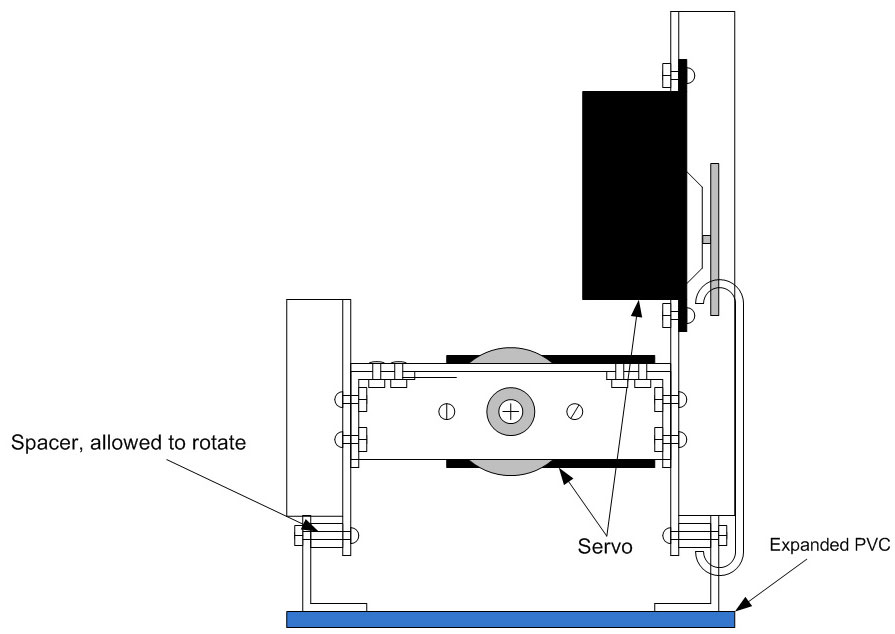
FIGURE 3. Top view.
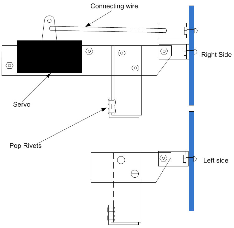
FIGURE 4. Side views.
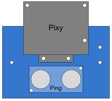
FIGURE 5. Front view of PVC Board.
Software for the Servo Motors and PING)))
The Arduino website (www.arduino.cc) provides a library for operating the servo motors. At the top of the program, the following statements are added:
#include <Servo.h>
// Create two Servo objects
Servo pan_servo;
Servo tilt_servo;
Then, add in the setup portion of the Arduino program:
// Set pins for servos
pan_servo.attach(48);
// attaches the servo, on pin 48 of the Arduino
// Mega 2560, to the servo object
tilt_servo.attach(49);
// attaches the servo, on pin 49 of the Arduino
// Mega 2560, to the servo object
This creates two servo objects: one for the pan and one for the tilt servo. In the setup portion of the program, connect them to specific output pins on the Arduino. The particular pins have headers connected to them so the servo plugs can be easily attached. To position the servos so the expanded PVC board is facing forward (pan) and level (tilt), these statements are added:
// Center servos
pan_servo.write(94);
// center position value
tilt_servo.write(65);
// center position value
Positioning the servos to control the pan and tilt of the PING))) board is just that easy. The values needed to come to a center position will vary based on the pan/tilt mechanism used and will have to be changed accordingly.
The software to send a PING))) sonar burst and obtain the distance of an object in front of it is also fairly simple. The following example was taken directly from the Arduino website, and was added to the program without modification:
void send_ping()
{
// The PING))) is triggered by a HIGH pulse of
// 2 or more microseconds.
// Give a short LOW pulse beforehand to ensure
// a clean HIGH pulse:
pinMode(pingPin, OUTPUT);
digitalWrite(pingPin, LOW);
delayMicroseconds(2);
digitalWrite(pingPin, HIGH);
delayMicroseconds(5);
digitalWrite(pingPin, LOW);
// The same pin is used to read the signal
// from the PING))): a HIGH pulse whose
// duration is the time (in microseconds) from
// the sending of the ping to the reception of
// its echo off of an object.
pinMode(pingPin, INPUT);
duration = pulseIn(pingPin, HIGH);
//Serial.println(duration);
// convert the time into a distance
inches = microsecondsToInches(duration);
cm = microsecondsToCentimeters(duration);
}
long microsecondsToInches(long microseconds)
{
// According to Parallax’s datasheet for the
// PING))), there are 73.746 microseconds per
// inch (i.e. sound travels at 1130 feet per
// second). This gives the distance travelled
// by the ping, outbound and return, so we
// divide by 2 to get the distance of the
// obstacle. See: [url=http://www.parallax.com/dl]http://www.parallax.com/dl[/url]
// /docs/prod/acc/28015-PING-v1.3.pdf
return microseconds / 74 / 2;
}
long microsecondsToCentimeters(long microseconds)
{
// The speed of sound is 340 m/s or 29
// microseconds per centimeter.
// The ping travels out and back, so to find
// the distance of the object we take half of
// the distance travelled.
return microseconds / 29 / 2;
}
The global variables inches and cm will contain the distance to an object in front of the PING))) board after calling the send_ping() function.
This function positions the PING))) board with a pan and tilt, and then after a short delay, sends a ping:
void look(int pan, int tilt)
{
pan_servo.write(pan);
tilt_servo.write(tilt);
delay(1500);
send_ping();
}
The sample program is a simple avoidance sequence. The main loop contains the following:
temp = false;
for (int tilt = 40; tilt < 91; tilt += 25)
{
look(94,tilt);
if (inches < 15)
{
temp = true;
}
}
if (temp)
{
stepper_driver(HALF, ROTATE_LEFT, QUARTER, 50);
}
stepper_driver(HALF, FORWARD, HALF, half_rotation);
The pan/tilt mechanism is set to pan to a forward position and the tilt then looks up, center, and down. It pings in each of the three positions and remembers with the Boolean variable temp whether there is anything less than 15 inches in front, or slightly down or up in front of the robot. If there is something in front, the robot rotates to the left a little more than a quarter turn (50 steps). Otherwise, it continues in the forward direction.
This concludes the building of a small robot propelled by stepper motors. The next step of this project will be to add a Pixy camera to the pan/tilt mechanism and experiment with its capabilities. SV
PARTS LIST
| PART | SOURCE |
|---|---|
| Airpax MA82818 stepper motors or similar | All Electronics, Electronic Goldmine, MPJA Online |
| BUZ11A MOSFETS, 1K resistors, mini toggle switches, terminal strips, stand-offs, hookup wire | All Electronics |
| Header pins | Jameco |
| Printed circuit board | ExpressPCB |
| PING))) sonar | Parallax |
| Aluminum angle and square, machine screws, pop rivets, wheel couplings, caster, cable ties | Home Depot, Lowes |
| Expanded PVC | ePlastics |
| Dubro low bounce smooth wheels 3-1/2", NiCad 7.2 volt batteries, NiCad battery connectors, Futaba S3004 servo motors | Tower Hobbies |
Article Comments