Eye-Ears — My Interactive Looking/Hearing Robot
By Alan Schilling View In Digital Edition
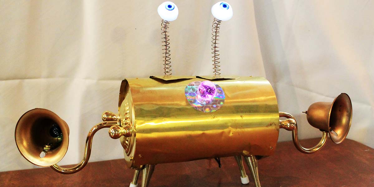
Yes, Eye-Ears is a little odd looking, but he is uniquely entertaining. The LED “eyes” wander back and forth, looking around the room. When someone approaches from either side of the ultrasound sensors (ears), it causes the eyes to jump and turn in their direction. Adults are surprised and children squeal with delight as Eye-Ears responds to their movements.
Eye-Ears Interactive Design
I used a Parallax BASIC Stamp 1 microcontroller as the heart of this project. A BASIC Stamp 2 can also be used. The eyes are controlled by two servos that normally rotate back and forth. When the ultrasound ears are activated, the program jumps to rotate the eyes left or right, depending on the input direction.
Description
Figure 1 shows Eye-Ears with the cover removed. Plastic toy eyes are mounted at the end of bent springs that are about 5” long. The eyes have white LEDs mounted inside which can be seen glowing from across a room.
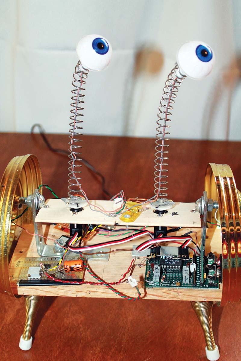
Figure 1.
The other end to the eye spring is attached to a set of servos (left/right) that cause them to rotate as controlled from the Stamp program.
A sonar range finder (LV-MaxSonar-EZ1) is mounted inside each ear. Figure 2 shows the sonar range finder mounted in one of the ears (old copper cups).
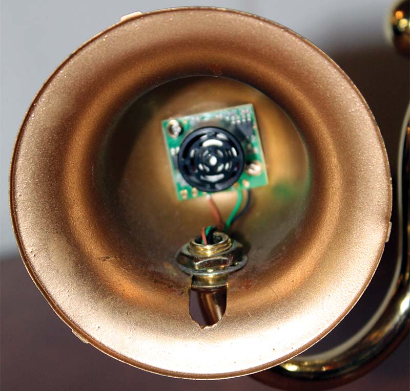
Figure 2.
The analog output from the sonar goes through a comparator, then to the input of the Stamp. The PWM output of the Stamp controls the servo’s movement to the eyes.
Schematic Description
Figure 3 is the schematic diagram for Eye-Ear.
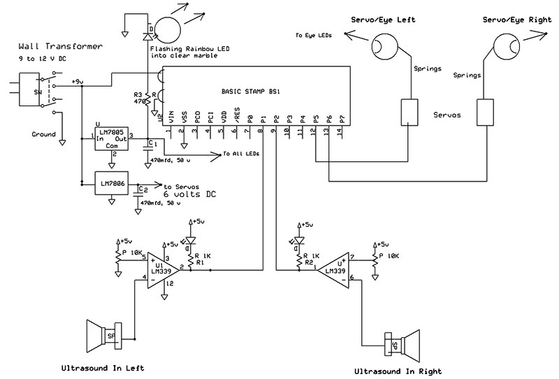
Figure 3.
Main power is derived from a nine volt, 500 mA wall transformer. Nine volts from the transformer goes directly to the carrier board’s nine volt battery connector. Voltage is regulated down with a LM7805; five volts for U1, all LEDs, and a LM7806; six volts for the servos. C1 and C2 are electrolytic capacitors to supply surge power during servo operation.
I used the analog output from the MaxSonar units that goes to five volts when objects are at close range. The sonar signal goes through an LM339 comparator for noise rejection. The reference voltage on pins 5 and 7 are set to about 0.4 volts — just high enough to prevent false triggering on background noise. Normally (no signal), the comparator outputs (ports 1 and 2) are low (LEDs on).
When the sonar signal exceeds the threshold, the output goes high which then goes to port 1 or 2 on the microcontroller. A Pulse Width Modulation (PMW) signal then goes to drive the eye servos to control their position. The power supply wires that go to the servos and sonar are not shown.
Software Program
The Stamp 1 is used for the program written in PBasic. The basic idea of the program is to rotate the eyes (servos) back and forth about 180 degrees, while checking for sonar signal inputs. A flow diagram of the program can be seen in Figure 4.
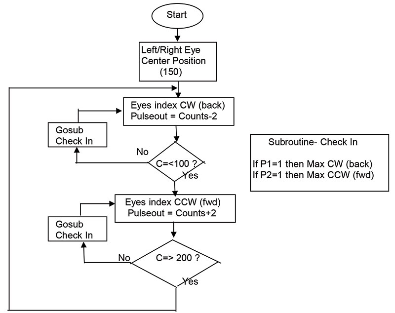
Figure 4.
The PULSOUT (port#) pulse time is used to control the servo position.
The Stamp controls the position of the servos from 100 (max CW) to 150 (center), then 200 (max CCW). (For BASIC Stamp 2s, the pulse time may be 500, 750, and 1,000 for similar positions).
My program starts with the counter set to 150 (center), then the counter counts down (minus two count) to 100 at the position of max CW. The IF statement checks the count each time through the loop.
When the count is equal to or less than 100, the program jumps to the up count (plus two) branch, and the servo goes to the 200 count, CCW. Finally, there is a “Check Input” subroutine where the input from the sonar is tested each time through the loop. The program jumps to the right or the left, depending on which input is detected (high).
Construction
This project (as are many of mine) is of an artistic nature and does not conform to any strict pre-arranged plans. As it goes, I have boxes full of parts; I have an idea of what I want to do; and I just have fun fitting things together to achieve my goals.
If you look at the photos, you will see that Eye-Ears is made of some common household items such as lamp fixture parts (ends), legs (spring doorstops), and ears (copper cups).
The wooden base is 3-1/2 x 7 inches, and was made to fit into the lamp base near the bottom. The door stops are screwed into the bottom wood, and the copper cups had holes drilled to fit the lamp fixture. There is a 2 x 5 inch platform mounted about two inches above the base on which the two eye servos are mounted (see Figure 5).
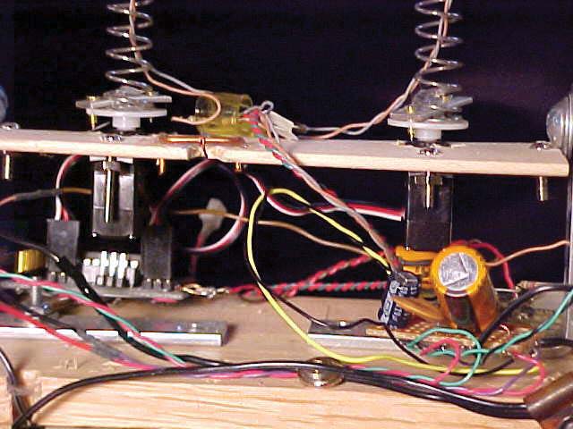
Figure 5.
In my first design, I had a third servo mounted to the base with a rod to control the platform tilting to swivel both eyes forward and backward. The tilting moved the platform and eyes outside the exit hole range and also the mechanics jammed, so I had to abandon this idea.
The Stamp carrier board is mounted on the lower right side (see Figure 6).
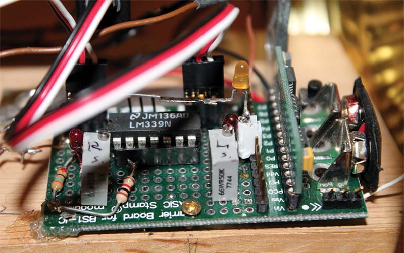
Figure 6.
The microcontroller board is plugged in vertically; you can see board numbers by the side of the board. All of the electronic components are mounted on the Stamp carrier board.There is just one IC (LM339), a couple of potentiometers, resistors, and three LEDs. The regulator ICs and capacitors are mounted on two different small boards in the front left and back.
To add a little extra pizzaz, I mounted a flashing rainbow LED to the front of Eye-Ears. I have found that by inserting a clear glass marble in front of the rainbow LED it appears to magnify the effects of the display several fold, thus improving the color presentation.
Electronic Assembly
All of the electronics are hard-wired to the Stamp carrier printed circuit board (PCB). Do not install the microcontroller onto the carrier board until after your soldering is done on the Stamp board. Install the 16-pin IC socket first, then the two potentiometers, and finally the output resistors and LEDs. I used a nine volt battery connector to run the power supply directly into the carrier board. Be sure polarity is correct.
Standard 2 mm pitch headers are used to connect directly to each servo. The six volt power supply will need to be wired directly to the headers for servo power. Many servos have different connections as far as which input is the power (+ and -) and servo signal. You may have to experiment somewhat to wire the header correctly. (On my small servo — Cirrus CS-20 BB — the red wire is +; the brown wire is -; and the orange wire is the PWM signal from the microcontroller.
Be sure to tie the grounds from the five volt regulator and the six volt and nine volts together, so there is a common ground. The Max Sonar requires five volts regulated, and needs three wires for +/- power and a signal output lead.
Before turning on power, check for shorts by measuring with an ohmmeter between pins 1 and 2 of the Stamp, and pins 3 and 12 of the IC socket. Before you plug in the ICs, connect power and check for proper voltage at the IC sockets (five volts), the servo header sockets (six volts), and +9 volts on the carrier board.
Turning It On and Checking Out Operation
I would suggest checking operation in two parts: sonar and IC; then the microcontroller. (Note: Use proper grounding procedures to eliminate electro-static component destruction.)
Check Sonar and IC Operation
The sonar output and comparator operation should be checked out before the microcontroller is installed. Insert IC U1 (LM339) into the socket. Stand clear from the front of the Max sonar units as they go through a short calibration cycle after turn-on.
Adjust the threshold voltage at the LM339 for about 0.5 volts at pins 5 and 7. With no signal from the sonar units, the outputs on pins 1 and 2 should be low (the output LEDs should be lit). When something is detected by the sonar unit, the output should go high and the LED should go out. You should be able to detect these voltage changes with an oscilloscope or voltmeter. If the LED is turning on too much, you may need to adjust the threshold level to reduce the background noise effects.
Program and Check-Out of the Stamp Operation
If you duplicate this project, you’ll need to be somewhat familiar with the Stamp 1 or 2. I learned basic programming with the help of Parallax training manuals and kits. For beginners, I recommend the Parallax basic education books What’s a Microcontroller? and Robotics With the BoeBot. The BoeBot kit is a great starting point for building your first robot (it comes with the book).
Once you are familiar with BASIC Stamp programming, you can try the simple programs in Figure 7 to see that the microcontroller is working.
Figure 7a.
‘{$STAMP BS1}
‘ BS1& 2 BOARD WORKING TEST!
‘ For blinking LED (Program running)
‘ Connect LED in series with 470 resistor.
‘ Plus side of LED to Pin zero, resistor side to ground.
again:
DEBUG “Hello World”, CR
TOGGLE 0
PAUSE 300
GOTO again
Figure 7b.
‘{$STAMP BS1}
‘ Servo control test to test for servo position
‘ Must re-load program each time pulse number is changed to check servo position.
again:
FOR B2 = 1 TO 5 ‘ repeat five times
PULSOUT 5, 150 ‘ pulsout to port 5, PWM
‘ rate is 150 (change to
‘ test servo position)
PAUSE 15 ‘ wait
NEXT ‘ goback to ‘FOR’ 5 times
GOTO again ‘ go back to again
Figure 7c.
‘{$STAMP BS1}
‘{$PBASIC 1.0}
‘ Tested 3/11/2013
‘ Servo Output test
‘ Test servo range with PWM program
‘ With BS1 typically PWM of 100 = max.CW, 200 max.CCW
‘ Servo position starts at 100 and counts up to 195 then returns to 100.
‘ You can change the “Start Variable” and/or the max count to test the servos range or rotation.
‘——Declaration—————-
SYMBOL counts = W0
SYMBOL Servo = W1
‘——-Variables—————-
counts = 0
servo = 100
‘————————————————
Start:
DEBUG “Start” ‘ Editor prints Start Servo going Clock Wise
FOR counts = 1 TO 100 ‘ Pulse width from 1 to 2 ms
servo = servo +1 ‘ servo counts + 1 (counts up)
PULSOUT 5, servo ‘ output to port 5, servo count
PAUSE 15 ‘ wait 15ms
DEBUG W1 ‘ prints out Servo position
IF servo => 195 THEN goback ‘ if servo position is equal to or greater than 195 jump to goback below
NEXT ‘ next pulse width
goback: ‘ Servo goes Counter clockwise
DEBUG “ goback “ ‘ Editor print goback
FOR counts = 1 TO 100 ‘ for counts 1 to 100
servo = servo -1 ‘ servo counts go down (-1)
PULSOUT 5, servo ‘ Output port 5, servo count
PAUSE 15 ‘ wait 15ms
DEBUG W1 ‘ prints out servo position
IF servo =<105 THEN start
‘ if servo count is equal to or less than 105 then Start
NEXT ‘ go back to F\OR (until 100)
Figure 7d.
‘{$STAMP BS1}
‘{$PBASIC 1.0}
‘ Eye-Ear 8
‘ Edit for article
‘ Program to detect sonar movement then move and rotate left and right eyes together
‘ Added TOGGLE to pin zero, add LED+ R also
‘- - - -Delarations - - - -
SYMBOL counts = W0
SYMBOL LeftEye = W2
SYMBOL RightEye = W3
‘ - - - Initilazation - - - -
‘ variables
LeftEye = 150
RightEye = 150
OUTPUT 0
‘ - - - - Start Program - - - -
DEBUG CLS
‘DEBUG “START PROGRAM “
PAUSE 3000 ‘ delay for Sonar self calibration
‘DEBUG “ GO “
Start: ‘ Start of main program
GOSUB moves
‘ moves subroutine is to output pulses to right/left eye 10 times
fwd:
DEBUG “ fwd “ ‘ Forward rotates eyes (servos) Clock-Wise
FOR counts = 1 TO 50 ‘ right & left eyes max right CW
righteye = righteye -2 ‘ slow step rate counts down by -2
lefteye = lefteye -2
IF righteye =< 100 THEN back
‘ if right eye is equal to or less than 100 then back
GOSUB moves ‘ pulse servos 10 times
GOSUB checkin ‘ goto checkin subroutine to see if input
NEXT ‘ return to FOR
back:
DEBUG “Reverse “ ‘ right & left eyes max left CCW
FOR counts = 1 TO 50
righteye = righteye +2 ‘ count + 2
lefteye = lefteye +2
IF righteye => 200 THEN fwd ‘ if pulsout is greater than 200 then fwd (CW)
GOSUB moves
GOSUB checkin
NEXT
moves: ‘sends pulses to servos x10
FOR counts = 1 TO 10
PULSOUT 6, righteye
PULSOUT 5, lefteye
PAUSE 5
NEXT
RETURN
checkin:
TOGGLE 0 ‘ blink pin zero (LED), shows Stamp operation
‘ Check for ultrasonic input, Left & Right
INPUT 1
INPUT 2
IF PIN1=0 AND PIN2=0 THEN norm ‘ If normal keep on rotating eyes servo
IF PIN1=1 AND PIN2=0 THEN maxrt ‘ If pin1 high then max right
IF PIN1=0 AND PIN2=1 THEN maxlft ‘ If pin 2 high then max left
IF PIN1=1 AND PIN2=1 THEN norm ‘ If pin 1 & 2 high then normal rotate
maxrt: ‘ sonic sence righteye max right
DEBUG “MAX RIGHT “ ‘ print out MAX RIGHT
FOR counts = 1 TO 10
righteye = 110 ‘ right eye is 110 position
lefteye = 110 ‘ left eye is 110 position also
GOSUB moves
NEXT
PAUSE 100
GOTO back ‘ eyes servo start to rotate back
maxlft: ‘ sonic sence lefteye max left
DEBUG “MAX LEFT”
FOR counts = 1 to 10
righteye = 190
lefteye = 190
GOSUB moves
NEXT
Pause 100
GOTO fwd
norm:
RETURN
Figure 7.
Carefully plug in the microcontroller board, but don’t connect the servos just yet. Download a few short programs to check the Stamp to see if it is working, and then check servo operation.
Program 7a is used to check the operation of the Stamp simply by blinking an LED.
This program tells you that the power supply is working; the microcontroller is working and communicating with the computer editor. If the LED is blinkin,g you can plug in and check the servos.
Program 7b is to confirm that the servos are working. You can check either servo (PULSOUT pin 5 or 6). Try changing the PULSOUT count (starts at 150) to 100 or 200, or any number in between to see the servo change position.
Program 7c will move the servos (step the counts through); first CCW, then CW. You can change the IF count value to see the servo position control.
Program 7d is the code for the whole Eye-Ear movement with input detection.
Comments are included and debug statements are used to help you follow the program as it steps through.
Check Eye-Ear operation by holding an object (hand) in front of one of the ears; the eyes should quickly move in that direction. The same is true with the other ear/eye operation.
Going Further
The whole idea of this project was to build something to have a person/robot interaction.
One can use the sonar detectors to perform other types of actions. You could have a hand pointing or a mannekin head that rotates toward a detected object.
Use your imagination and artistic abilities to create an interactive robot that fascinates people and excites children to the field of electronics and robotics. SV
Parts List
| Description | Type | Value | Source |
| LM339 | IC, Quad Comparator | ||
| R1,R2 | Resistor | 1K ohm, 1/4 watt | Jameco.com |
| R3 | Resistor | 470 ohm, 1/4 watt | www.goldmine-elec-products.com/ |
| LED1,LED2 | Small LEDs | RadioShack | |
| LED L,R | Eye LEDs, super bright white (left/right) | ||
| LED3 | Flashing Rainbow LED | ||
| LM7805 | Regulator | Five volt | |
| LM7806 | Regulator | Six volt | |
| C1,C2 | Capacitor (filter) | 470 mfd @ 50 volts | |
| P1,P2 | Potentiometers | 10K, 10 turn | |
| Switch | Mini Toggle SPST (power on/off) | ||
| Transformer | Wall Transformer | Nine volts | |
| Miscellaneous Parts (Artistic) | |||
| Toy Eyeballs | |||
| Main body (enclosure) brass/copper metals | Hobby Lobby | ||
| Legs | Door Stops | Hardware store | |
| Springs | Eyeball Extenders (about five inches) | Hardware store | |
| Ears | Cups, brass, etc. | Garage sales | |
| Light Fixtures | Antique Shops, etc. | ||
| BASIC Stamp 1 (or 2) Microcontroller | Parallax.com | ||
| Stamp 1 Carrier Board (with nine volt connector) | |||
| Stamp 1 Serial Adapter (you will also need to be able to use the editor and connection cable) or new BASIC Stamp 2 Activity Kit, USB version | |||
| Servos 1 & 2 | Cirrus CS-20BB (micro servos; left & right) | ||
| Sonar 1 & 2 | MaxSonar-EZ -EZ1 | Maxbotix.com | |
Article Comments