Make a Splash with an Underwater Quadcopter ROV — Part 2
By Theron Wierenga View In Digital Edition
We pick up our project this time with a description of the redesigned printed circuit board (PCB) that was produced to reduce its size, tidy up our circuit, and minimize the length of the signal lines.
New Printed Circuit Board
After getting all the bugs worked out both in hardware and software, a new compact PCB was designed for a four inch box. This PCB (shown in Figure 1) contains all the original features of the prototype design with some additions mentioned in the "Thoughts on Improvements" section.
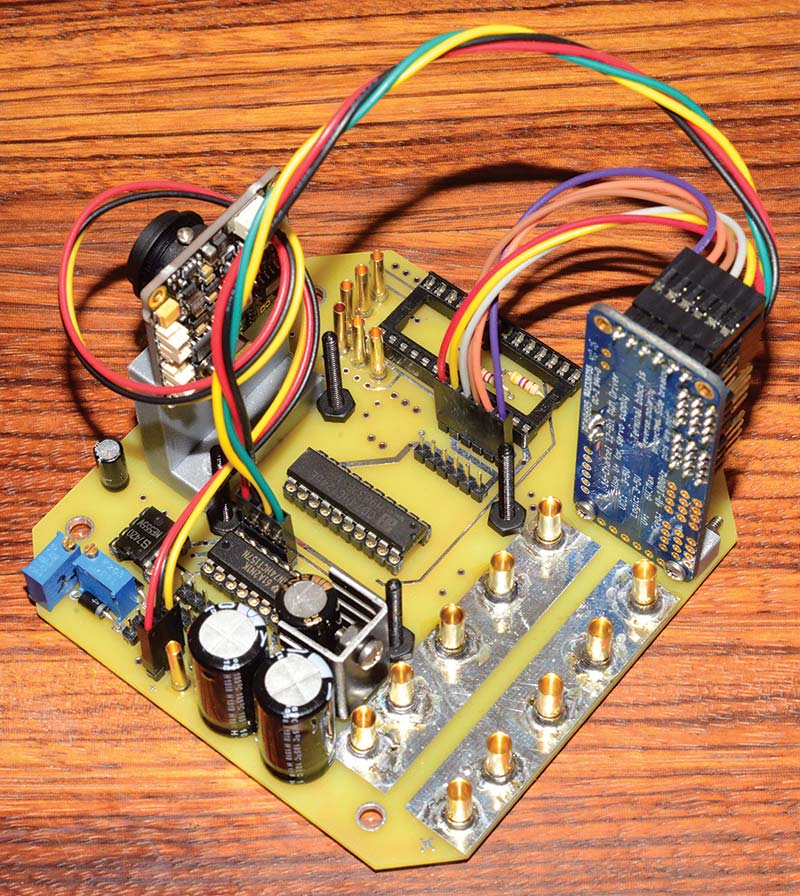
Figure 1. The four inch PCB with all components soldered and partially assembled.
This 3.8 inch square PCB can be installed in the 6 x 6 x 4 inch Cantex junction box as shown in Figure 2, but should also just fit into a 4 x 4 x 4 inch Cantex box when its corners are cut off.
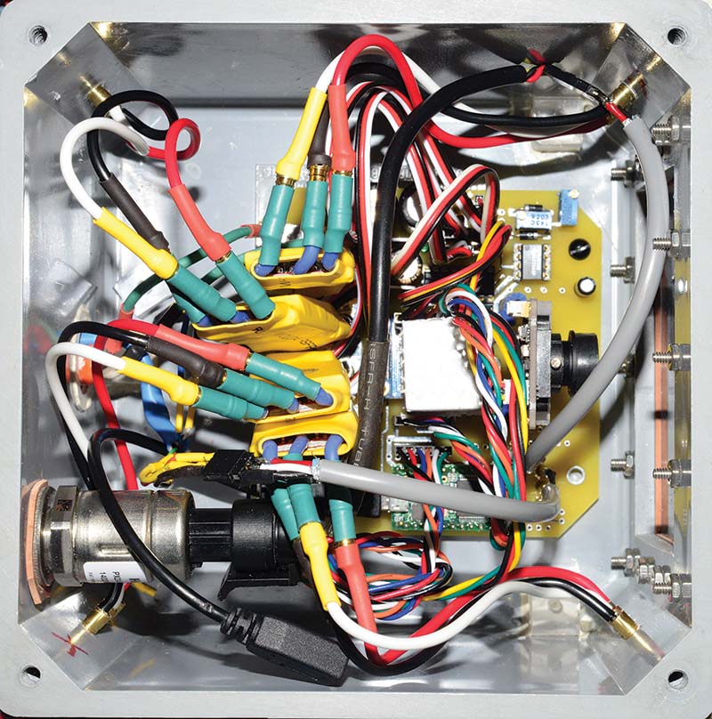
Figure 2. The four inch PCB mounted in the 6 x 6 x 4 inch Cantex box.
Wire placement will be a challenge in a 4 x 4 x 4 inch box. Be aware that there are other brands of these size junction boxes that look similar to the Cantex boxes, but their inside dimensions are smaller.
An ExpressPCB layout of this PCB is in the downloads for this article. It includes the part positions on the board. If you don’t already use ExpressPCB, it’s an easy matter to download their free software so you can read the layout and see the part positions.
Here are some important things to know about this PCB:
- A header plug for an Arduino micro SD card breakout board was included. This uses the SPI lines on the Teensy 3.1/3.2. Jumper wires will be necessary for connecting to the SPI pins 10, 11, 12, and 13 on the Teensy 3.1/3.2, which are brought out to pads and then connected to other pads just above the header plug for the SD card. The SD card board is not necessary for operation of the Quad_ROV, but was added for possible troubleshooting. No code to write to the SD card appears in the software.
- The ESCs (electronic speed controllers) are mounted vertically, with the power lines connected to the PCB by 3.5 mm bullet connectors. The positive connections are at the edge of the board.
- An LED with a limiting resistor is connected to pin A2, and a second LED with a limiting resistor is connected to pin 9. These can be used for any purpose. An LED with a limiting resistor for a power indicator was added to the 12 volt supply. The limiting resistor for the power indicator may have to be installed on the bottom of the PCB, depending on the size of the filter capacitors used. If these LEDs remain inside the box, they may need to be shielded from the video camera window as they could cause reflections in the window and obscure the video image. These LEDs can be installed in the box wall to point outside by using marine epoxy in an appropriately sized hole for the LED.
- The four resistors installed under the Teensy 3.1/3.2 can also be installed on the bottom of the PCB. A socket for the Teensy 3.1/3.2 is recommended, and may necessitate installation on the bottom of the PCB.
- The Adafruit 9-DOF board is installed upside down and hung from four small rubber bands connecting the holes on the board to size 4-40 stainless machine screws installed in holes just outside the outline of the Adafruit 9-DOF. The 9-DOF sensor can be further isolated from vibrations by raising and separating it from the PCB with a piece of foam rubber. See Figure 3 for details. Some additional mass attached to the bottom of the 9-DOF board can also help reduce vibrations.
- There are six-pin header jumpers installed between the Adafruit 9-DOF and a six-pin header on the PCB, and the servo driver board and another six-pin header on the PCB. The plug to the servo driver board is the one closer to the Teensy 3.1/3.2. There is a four-pin header jumper installed between the servo driver board output pins 0-3 and a four-pin header on the PCB next to the 74LS157 multiplexer. Be sure to check for the correct orientation of these plugs.
- Small 1/4 inch square pieces of plastic or other suitable material will need to be cut to mount the servo driver board. A piece one inch long will work for this driver board that mounts vertically on end. A 1-1/4 inch long piece of 1/4 inch plastic is needed for the video camera mounting; the height is determined by the camera size and window size made in the box. The two hole placement for mounting the video camera is for a wide angle model I had, and is mounted on a small 1-1/4 inch PCB. Other cameras may be larger and require a work-around for using the two mounting holes. It’s possible to mount an inverted L-shaped piece of plastic with the two mounting holes that would place a larger camera higher off the PCB and back from the edge.
- Connections for the tether — which need to be removed when the PCB is removed from the box — are implemented with 2 mm bullet connectors. The female end is soldered to the PCB and the male to the end of the tether wire. These solve the problem of loose connections causing intermittent serial signals. These should be the first parts soldered to the board as they are a tight fit. The pressure sensor is also connected to the PCB with 2 mm bullet connectors.
- A two-pin header test point was added near the 555 timer. This makes a connection to the output of the timer available when calibrating the minimum servo signal.
- The three-pin header that connects to the video board has the +12 volts, and the video signal on the ends and the ground wire in the middle. Make sure the connector on the cable of your video board has the same connections or you will need to switch some of its pins.
- The output voltage of the pressure sensor goes to pin A0 on the Teensy 3.1/3.2 for direct reading. Using pin A0 will limit the values read to 3.3 volts, although the pressure output can go higher. The pressure output voltage can also be scaled down by a resistor divider, 4.7K and 10-turn 5K resistors, and is then brought out to pin A1. Changes will be needed in the software to scale the pressure to depth if this method is used.
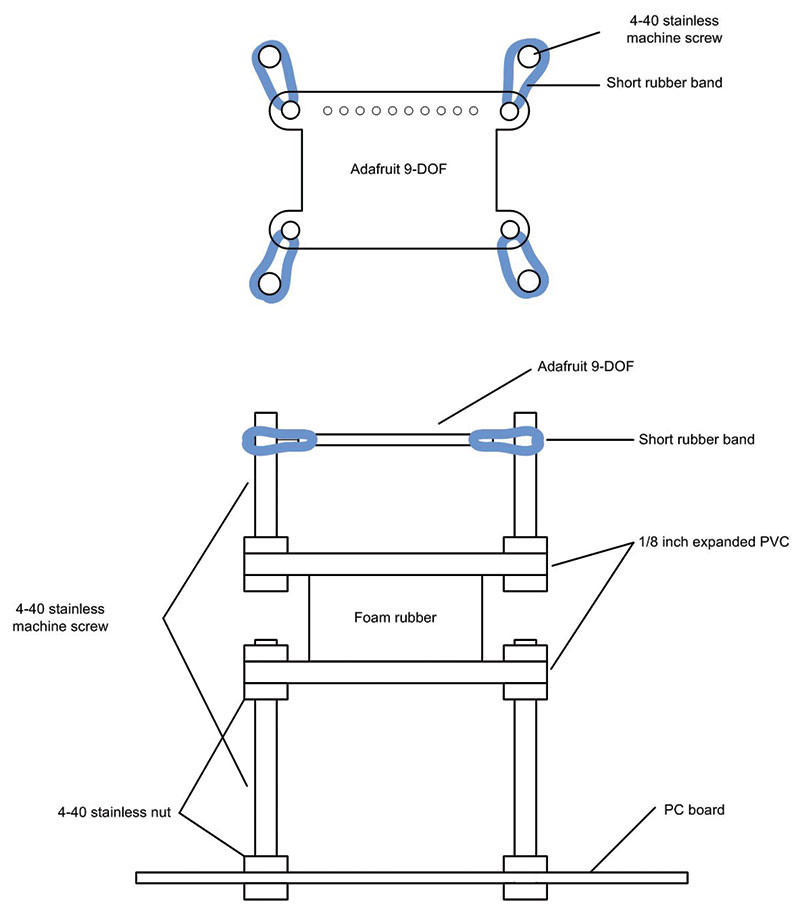
Figure 3. Mounting the Adafruit 9-DOF sensor.
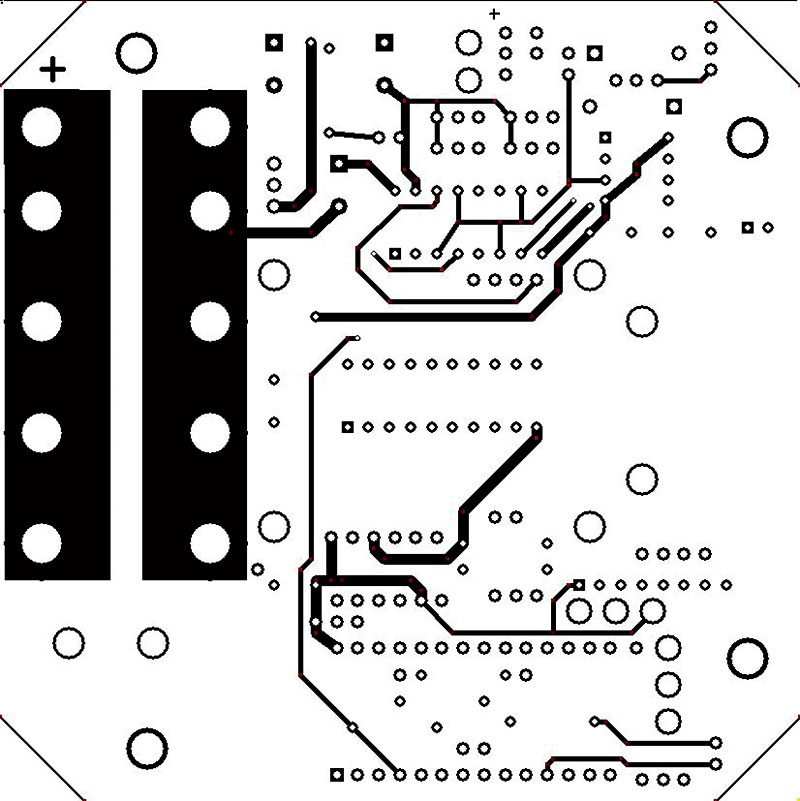
PCB top.
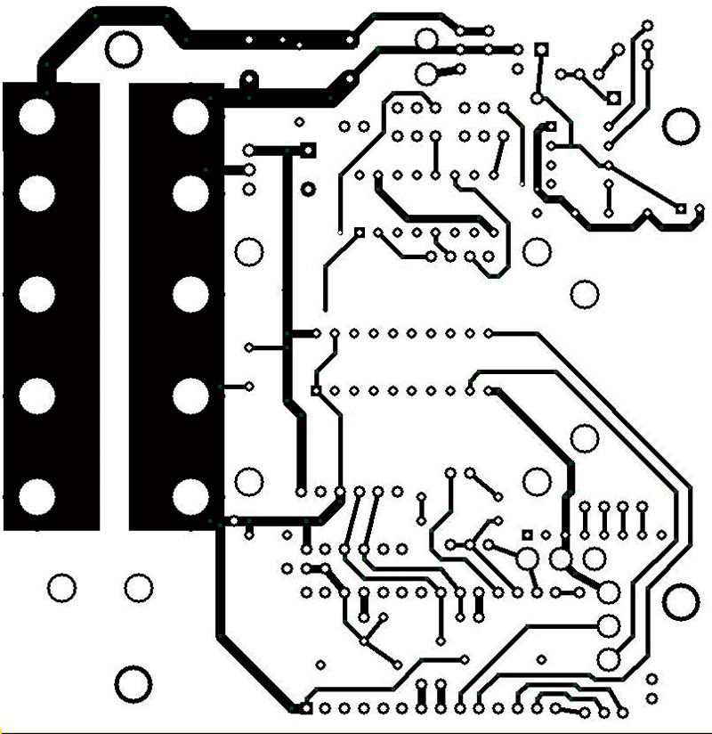
PCB bottom.
PID Controllers
Quadcopters employ PID controllers in their software to implement the necessary fly-by-wire system. A quadcopter has four degrees of freedom — pitch, roll, yaw, and height — and the Quad_ROV replaces height with depth. It’s impossible for a human to smoothly control all four of these variables using two joysticks manually.
When the two joysticks are allowed to go to their neutral position, the Quad_ROV should hover in place with the software reading the sensors and maintaining equilibrium. PID stands for Proportional, Integral, and Derivative, and is basically a feedback loop system to insure that changes in the motor’s speed are done smoothly.
The cruise control in a car is operated by a PID mechanism. If your cruise control is set for 70 MPH and you slow to 45 MPH, when you re-engage the cruise control it rapidly accelerates up to 70 MPH. However, just before it gets to 70 MPH, it slows down the acceleration so that it will not overshoot the 70 MPH limit. This is the function of a PID controller.
For a full treatment of PID controllers, check out the Wikipedia article at https://en.wikipedia.org/wiki/PID_controller.
Another good reference is Chapter 7 in the book, Pro Arduino, by Rick Anderson and Dan Certvo, Apress, 2013.
Fortunately, we don’t have to write our own software for this complex algorithm. There is an Arduino library available that does this. It can be found at https://playground.arduino.cc/Code/PIDLibrary.
Using this library is pretty straightforward. Here’s a very basic example from the author of the library:
/************************************************
* PID Basic Example
* Reading analog input 0 to control analog PWM
* output 3
***********************************************/
#include <PID_v1.h>
//Define Variables we’ll be connecting to
double Setpoint, Input, Output;
//Specify the links and initial tuning
//parameters
PID myPID(&Input, &Output, &Setpoint,2,5,1, DIRECT);
void setup()
{
//initialize the variables we’re linked to
Input = analogRead(0);
Setpoint = 100;
//turn the PID on
myPID.SetMode(AUTOMATIC);
}
void loop()
{
Input = analogRead(0);
myPID.Compute();
analogWrite(3,Output);
}
A complete list of the PID controller methods includes PID(), Compute(), SetMode(), SetOutputLimits(), SetTunings(), SetSampleTime(), SetControllerDirection(), GetKp(), GetKi(), GetKd(), GetMode(), and GetDirection().
The simple example above does not use the SetOutputLimits() method, which has default values of 0 and 255 for the minimum and maximum. Instead of 0, the minimum is set to –255 in the Quad_ROV controller software because our Setpoint values (the angles) will include negative values. The controller program also uses the SetSampleTime() method with a parameter of 10 milliseconds, which produces 100 Hz updates.
The direction parameter in the PID object is normally set to DIRECT. However, for the depth PID, this must be set to REVERSE. The motors will need to slow down to allow the depth to increase.
The challenge of getting a PID controller to work correctly involves setting the Kp, Ki, and Kd gains correctly. There are books written on this subject; however, the Wikipedia article has some good animations that help to clarify this subject.
After some experimenting, it was found that Kp = 3.0, Ki = 0, and Kd = 0.3 for depth, and Kp = 2.5, Ki = 0, and Kd = 0.5 for roll and pitch was workable. I didn’t implement yaw in my prototype. No doubt these gains could be improved with finer tuning.
The Teensy 3.1 software for controlling the Quad_ROV will need four PID controllers: one each for pitch, roll, yaw, and depth. The program to control the Quad_ROV will be a large loop that will:
- Read the current joystick positions to get the desired setPoints for roll, pitch, yaw, and depth PIDs.
- Read the sensors to determine the current input values of the roll, pitch, yaw, and depth PIDs.
- Feed these values to the four PID controllers and have them compute new output values.
- Combine and scale the values output by the PID controllers, and send the values as servo signals to the ESCs that will drive the motors.
Figure 4 is a basic flowchart of the software controlling the Quad_ROV.
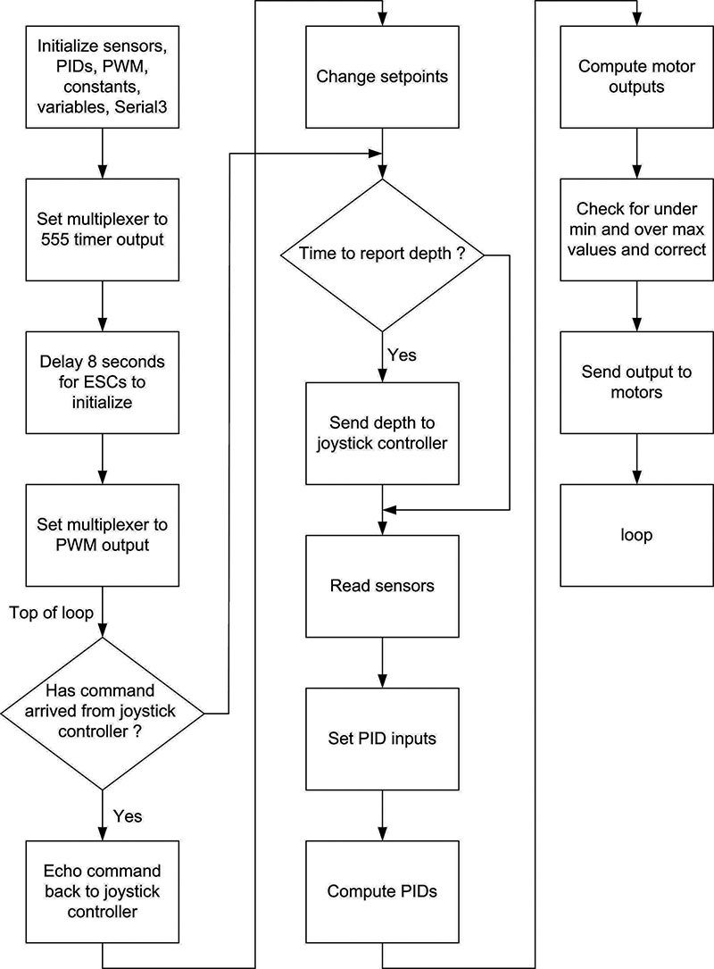
Figure 4. Flowchart of the controller software.
The complete software for both the Quad_ROV controller and the joystick controller is available in the downloads for this article.
Controller Software Notes
Following are some of the more important software fragments from the controller program.
In Setup(), the ESCs need to initialize normally. First, the 74LS157 multiplexer is immediately set to send the 555 timer signal to the ESCs. Next, the Adafruit servo driver board is started and the minimum signal (minus a little) is output. It’s important that the MIN_SIGNAL value is set so that the motors will always be turning.
If MIN_SIGNAL allows the motors to turn off, the result will be an uncontrolled wobble of the Quad_ROV. This is because there is some inertia to overcome when the motors restart, causing a delay in response. After the ESCs have had a delay of eight seconds to start up, the multiplex signal is set low to allow the signals from the servo driver board to connect to the ESCs for normal operation:
#define MULTIPLEX 2
// For switching servo signal into ESCs
#define MAX_SIGNAL 325 // = 1737 uSec
#define MIN_SIGNAL 208 // = 1112 uSec
// Allow ESCs to initialize
pinMode(MULTIPLEX, OUTPUT);
digitalWrite(MULTIPLEX, HIGH);
// Make sure 555 timer is going to ESCs
// Setup PWM
pwm.begin();
pwm.setPWMFreq(50);
// Analog servos run at ~50 Hz updates
pwm.setPWM(0, 0, MIN_SIGNAL - 5);
// Turn them all off
pwm.setPWM(1, 0, MIN_SIGNAL - 5);
pwm.setPWM(2, 0, MIN_SIGNAL - 5);
pwm.setPWM(3, 0, MIN_SIGNAL - 5);
delay(8000);
// Wait for ESCs to initialize
digitalWrite(MULTIPLEX, LOW);
// ESCs should be powered up so switch input
This next fragment shows the basics of the main loop().
The first section checks for any serial commands coming from the joystick controller. If something is received, it is first echoed back to the joystick controller to indicate it has been received correctly. Then, using the first character in the received string (which is a letter), it determines what setpoint must be changed, and with the extracted value changes that setpoint.
The values for the roll and pitch setpoints are multiplied by 2.0; this can be adjusted to determine how aggressive the roll and pitch will be. The yaw setpoint goes from 0 to 360 degrees, so overflow and underflow are dealt with if necessary.
The same is done for the depth setpoint which insures the Quad_ROV will not go below 50 feet:
mySerialEvent();
if (stringComplete)
{
Serial3.println(inputString);
// Echo command back to the joystick controller
Serial.println(inputString);
String subStr = inputString.substring(0, 1);
// Get the letter
int len = inputString.length() - 1;
String temp = inputString.substring(1, len);
float val = temp.toFloat();
// Get the value
inputString = “”;
stringComplete = false;
if (subStr == “R”) { rollSetpoint = val * 2.0;
}
if (subStr == “P”) { pitchSetpoint = val *
2.0; }
if (subStr == “Y”)
{
yawSetpoint = yawSetpoint + val;
if (yawSetpoint > 360.0) { yawSetpoint -=
360.0; }
if (yawSetpoint < 0.0) { yawSetpoint +=
360.0; }
}
if (subStr == “D”)
{
depthSetpoint = depthSetpoint + val;
if (depthSetpoint < 510) { depthSetpoint =
510; } // surface about 520
if (depthSetpoint > 1150) { depthSetpoint =
1150; } // 50 feet
}
The portion of the main loop() that actually controls the movement of the Quad_ROV is next.
The sensors are read from both the Adafruit 9-DOF and the pressure sensor, and then each value is sent to the smoothing functions.
These functions contain a circular buffer which averages the last 30 sensor reads. This helps in smoothing out the sensor values, which tend to vary slightly. With the new averaged sensor readings, the four PIDs compute a new output value. These values are then used to generate a new thrust value for each motor.
Note that the depthOutput is added to all four motors. If only the depth needs to be changed, these four motors will all run at the same speed, and increase or decrease their speed depending on whether the Quad_ROV needs to go up or down. With the rollOutput variables, the two motors on either the right or left are increased in speed while the opposite motors are decreased in speed. This will roll the Quad_ROV to the right or left.
The same happens with the pitch and yaw output values, but the + and - signs differ on specific motors to create the pitch or yaw motion. After the four motor values are computed, they are checked and truncated if needed to stay within our MIN_SIGNAL and MAX_SIGNAL limits.
Note that the divisor variable can be adjusted to change the overall thrust of the brushless motors. This may need to be adjusted depending on what motors and ESCs are used. The motor[] values are then sent to the motors by assigning them in the four servo driver pwm.setPWM() methods:
readSensors();
// Read roll, pitch and yaw values
temp = analogRead(A0);
// Read the depth pressure sensor
depthInput = double(smoothdepthSensorReadings (temp));
rollInput = smoothrollSensorReadings(orientation. roll);
pitchInput = smoothpitchSensorReadings
(orientation.pitch);
yawInput = smoothyawSensorReadings(orientation.heading);
rollPID.Compute();
pitchPID.Compute();
depthPID.Compute();
yawPID.Compute();
motors[0] = (int)(((depthOutput + rollOutput + pitchOutput + yawOutput) / divisor) * range + min_double);
motors[1] = (int)(((depthOutput - rollOutput + pitchOutput - yawOutput) / divisor) * range + min_double);
motors[2] = (int)(((depthOutput - rollOutput - pitchOutput + yawOutput) / divisor) * range + min_double);
motors[3] = (int)(((depthOutput + rollOutput - pitchOutput - yawOutput) / divisor) * range + min_double);
if (motors[0] > MAX_SIGNAL) { motors[0] = MAX_SIGNAL; }
if (motors[1] > MAX_SIGNAL) { motors[1] = MAX_SIGNAL; }
if (motors[2] > MAX_SIGNAL) { motors[2] = MAX_SIGNAL; }
if (motors[3] > MAX_SIGNAL) { motors[3] = MAX_SIGNAL; }
if (motors[0] < MIN_SIGNAL) { motors[0] = MIN_SIGNAL; }
if (motors[1] < MIN_SIGNAL) { motors[1] = MIN_SIGNAL; }
if (motors[2] < MIN_SIGNAL) { motors[2] = MIN_SIGNAL; }
if (motors[3] < MIN_SIGNAL) { motors[3] = MIN_SIGNAL; }
pwm.setPWM(0, 0, motors[0]);
pwm.setPWM(1, 0, motors[1]);
pwm.setPWM(2, 0, motors[2]);
pwm.setPWM(3, 0, motors[3]);
Video
How do you view the live video signal produced by the small camera inside Quad_ROV? Here’s the simple method I use. There are several small video adapters available on Amazon or eBay that make this task easy.
Figure 5 shows the model I have.
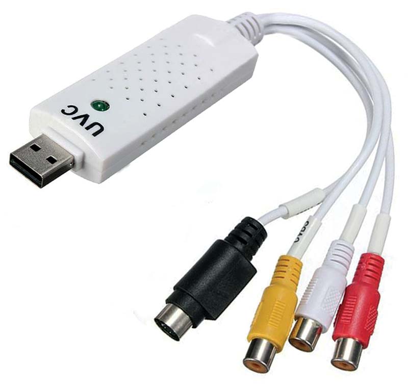
Figure 5. NTSC to USB video adapter.
It came with a mini DVD containing software that not only displays the video signal, but will record it as well. The adapter plugs into a USB port on your laptop and the NTSC video signal from the Quad_ROV goes into the yellow RCA jack on the adapter. This model also has a red and white jack for audio, and a black jack for S-Video input, which are not used.
Thoughts on Improvements
The Quad_ROV that I built is really a prototype. Here are some thoughts on changes I would make for improvements:
- The number one problem I had with this project was vibration, causing the 9-DOF sensor to give bad readings. My solution was neoprene rubber pads between the motors and the end of the arms. Note that four holes in the neoprene mount the motor to the neoprene, and another four mount the neoprene to the arm. This is not the same as just sandwiching a layer of neoprene between the arm and motor with screws through the arm to the motor. Neoprene pads were also used between the arm structure and the Cantex box. The Adafruit 9-DOF is also suspended with rubber bands as described below in number 6 of the new PCB. It’s important to check the output values of the 9-DOF sensor while running the motors in a static test out of the water. The pitch and roll angles should not vary by more than a fraction of a degree.
- The waterproof box for the controller circuit board is big, adding to the amount of ballast needed; this could be made smaller. With a well designed PCB, a 4 x 4 x 4 box should be possible as discussed earlier. It might be just as easy to create your own box out of something like 1/2 inch thick Plexiglas, which would allow you to set specific dimensions. A custom designed box could also be made with a 3D printer. This would need to be tested for what pressure it could withstand, and the wall thickness adjusted. A smaller box should also be more resistant to pressure and allow for greater depths.
- While I originally soldered the ESC power wires directly onto the PCB, I later installed 3.5 mm gold plated bullet connectors. This allows you to easily replace an ESC by simply plugging in a new one. This also allows for separation of the 12 volt power lines from the PCB for calibration. Some ESCs come with bullet connectors already installed.
- I found that a set of 20 amp ESCs overheated very easily with continuous use, so I changed to 30 amp models.
- The 0.1 inch header connectors used on small boards like the Adafruit 9-DOF and servo driver boards can cause problems. Many hours of time were spent finding loose connections! I also used these header pins to connect the signals from the tether and the pressure sensor to the PCB. The header pins — used with mating female jumpers — are prone to intermittent failure. This can be very frustrating since when this happens, the waterproof box must be taken apart to get at the wiring inside. In the future, I would use small 2 mm bullet connectors. These should also be used for the connections from the signal lines from the tether and the pressure gauge. Small bullet connectors could also be used on the two Adafruit boards by soldering them to wires connected to the board pads instead of using the header pins that come with these boards. Mating bullet connectors would be placed on the PCB. Larger bullet connectors were used for the power connections from the tether. This worked well.
- It’s a real nuisance to have to remove the cover from the waterproof box to make a change in the software for the Teensy 3.1. It shouldn’t be too difficult to make access to a USB jack on the outside of the waterproof box. My thought is to take a six inch micro USB extension cord and embed the female end in waterproof epoxy inside half of a 1/2 inch female threaded PVC coupling. The opposite end is plugged into the Teensy 3.1 USB connector. The threaded coupling end is then epoxied into a hole in the waterproof box wall. Because the USB connecter is inside the threaded coupling, you only need to screw in a 1/2 inch PVC threaded plug on the outside to make it waterproof. Removing the plug temporarily allows access to the USB connector embedded inside.
- Larger and higher quality joysticks would be more ergonomic, although the small ones worked fine for me. This will increase the box size if an LCD panel is included. Another possibility is a much larger box that would not be handheld, but could contain additional circuitry. A digital readout of current being delivered to the Quad_ROV would be a nice feature.
- A circuit breaker would also be a good addition. It might be placed inside the Quad_ROV, but topside would be more convenient.
- It’s impossible to read what the real time values are for different variables once the Quad_ROV is in the water. This can make development and troubleshooting difficult. While these values could be sent up the tether as serial data, this would slow the processor to an unacceptable level. The answer might be to add an SD card plug to the controller circuitry. Various data could then be written to the SD card in real time and analyzed after a test run. This would require use of the SPI pins, and pin assignments on the Teensy 3.1 would need to be changed.
- Twenty centimeter long header pin jumpers were used; using shorter ones would make for less of a wire tangle when they are installed.
- There is not a light for underwater illumination on this prototype, but it could be easily added. A waterproof light — like that shown in my March 2016 SERVO article — would have its power leads fed into the box and directly connected to the 12 volt power line.
- While developing the controller software, it was necessary to reprogram the Teensy 3.1 many times. The six inch PCB used for development has the Teensy 3.1 in a position where it is impossible to plug and unplug the micro USB cord used for programming. Instead, a six inch USB extension cable was permanently plugged into the Teensy 3.1 and brought out to the top of the box to make connections to the programming cable easy.
- While it’s convenient when testing to be able to strap the ballast onto the Cantex box with bungee cords, this isn’t an ideal position. This positions the center of gravity quite low, and when a pitch or roll is required, it strains the motors attempting to attain the desired angle. A better placement might be between the Cantex box and the PVC mounting sheet that is attached to the arms. Once in place, this would make entering the Cantex box easier, as well as the ballast would not need to be removed. SV
Parts List
Quadcopter frame kit
Brushless motors with M4 threaded shafts (4)
Traxxas propellers, number 1533 (2)
Traxxas propellers, number 1534 (2)
30 amp ESCs (4)
Cantex junction box, number 5133710
12 volt sealed lead-acid battery
Teensy 3.1 or 3.2 microcontroller
Adafruit 9-DOF board
Adafruit servo driver board
NTSC 12 volt mini video camera
Pressure sensor, Honeywell type with 1/4 inch pipe thread, PX2AN1XX050PAAAX
555 timer
74LS157 quad two-input multiplexer
74LS245 octal bus transceiver
1N4001 diode (2)
2K ohm 10-turn trimmer, 0.1 inch pin spacing
5K ohm 10-turn trimmer, 0.1 inch pin spacing
20K ohm 10-turn trimmer, 0.1 inch pin spacing
220 ohm resistor, 1/4 watt
510 ohm resistor, 1/4 watt
1K ohm resistor, 1/4 watt
4.7K ohm resistor, 1/4 watt (4)
Red, Green, Blue LED
4.7 µF, 6.3 volt electrolytic capacitor
2,700 µF, 6.3 volt electrolytic capacitor
4,700 µF, 16 volt electrolytic capacitor
0.1 µF disk capacitor (4)
1/8 and 1/4 inch expanded PVC board
Soft neoprene rubber sheet 1/4 inch thick
Hard rubber sheet 1/8 inch thick for box gasket
Gasket rubber sheet for Plexiglas window and pressure sensor
1/4 and 1/2 inch thick Plexiglas
Headers with 0.1 inch spacing and various mating three-, four-, and six-pin, 4-6 inch long jumper cables
50 foot extension cord
Small battery clamps
60 foot Cat 5 cable
Printed circuit board
General-purpose sealed lead-acid battery, 12 volt/5 amp-hours
For the joystick controller:
Plastic project box, 200 x 120 x 75 millimeters
Mini joysticks (2)
LCD display, four-line x 20 character, with built-in I2C interface
Toggle switch
RCA style panel mount jack
Arduino Nano
Printed circuit board or perforated board to mount Arduino Nano
Headers with 0.1 inch spacing and various mating three-, four-, and six-pin, six inch long jumper cables
Mini stereo phone jack and mating plug
AA batteries (6) and battery holder
Various bullet connectors, screws, washers, spacers, and nuts (stainless steel and nylon), hookup wire, solder, small rubber bands, 1/4 inch Plexiglas, ceramic tile squares, duct tape, bungee cords, marine epoxy.
Article Comments