
Linear Actuator Update
By Theron Wierenga View In Digital Edition
Since writing the article “Building a Linear Actuator,” I have continued to experiment and improve the design. While the Hall-effect sensor is a good solution to finding a fixed position or a home position, it doesn’t tell you the linear distance the actuator has moved. Some type of encoder is needed to do this.
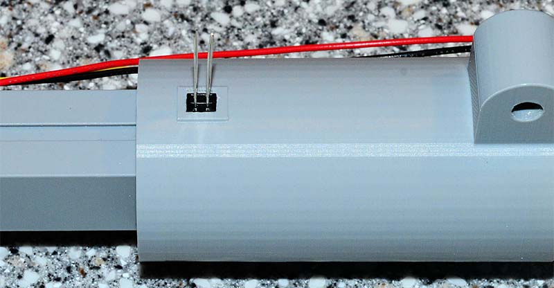
Experiments were done with a QRD1114 Reflective Object Sensor (Figure 1). A rectangular hole was created underneath the motor coupling in the motor housing to hold the QRD1114. A piece of black plastic electrical tape was wound half way around the motor coupling.
 \
\
FIGURE 1. A QRD1114 reflective object sensor inserted into a rectangular hole in the motor housing. Longer wires were attached to the sensor and then connected to the microcontroller.
With the IR sensor close to the surface of the coupling, a rising and falling pulse can be detected using the Arduino analogRead() function. This will detect a single rise and fall signal for each full turn of the threaded rod.
Multiple pieces of tape spaced around the circumference of the motor coupling will produce multiple pulses for each turn. This is a nice, inexpensive solution for an encoder.
The circuit to connect a QRD1114 to a microcontroller is shown in Figure 2.
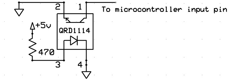
FIGURE 2. Circuit to connect a QRD1114 to a microcontroller.
The code to read this encoder is fairly simple. The function countTurns() accepts a count and the pin number of the QRD1114 connection. The function returns after the specified number of turns has occurred. The Serial.print lines can be removed for increased speed. I chose a value of 75 in this function for comparison because it fell nicely between the high and low inputs.
void countTurns(int count, int ir)
{
int tcount = 0, i = 0; // This assumes we start on reflective area
while (tcount < count)
{
while (i <= 75) // on reflective, output low
{
i = analogRead(ir);
Serial.println(i);
}
while (i > 75) // on the black, output high
{
i = analogRead(ir);
Serial.println(i);
}
tcount++;
Serial.print(“tcount = “);
Serial.println(tcount);
}
}
The Yellow Jacket series of planetary gear motors from goBILDA.com is a very nice solution for a linear actuator since it has a built-in encoder (Figure 3). There are 10 different models of this motor, ranging from 30 RPM and 3,470 oz-in of torque to 1,620 RPM and 76 oz-in of torque.
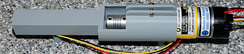
FIGURE 3. Yellow Jacket planetary motor installed in the motor housing of a linear actuator.
I experimented with the 1,620 RPM model which gives 25.9 pulses out the encoder for each turn of the output shaft. The planetary gears give a smooth operation with the benefit of added torque.
In order to use the encoder on the Yellow Jacket motors, five volts and ground are connected to the labeled pins (Figure 4).
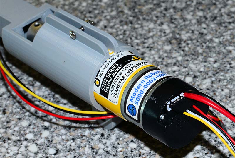
FIGURE 4. The end of the Yellow Jacket planetary motor showing a four-pin jumper cable plugged into the encoder pins.
The channel A pin is connected to a digital input pin. The following function will read pulses coming from the encoder. The function returns after the number of pulses has been received. Depending on which model you use, you’ll need to convert the number of pulses to turns.
void readYellowJacket(int count, int pin)
{
int tempCount = 0;
int doubleCount = count * 2; // We count transitions,
// 2 transitions for each pulse
int x, last = 0;
while (true)
{
x = digitalRead(pin);
if (x != last)
{
tempCount++;
if (tempCount >= doubleCount) break;
last = x;
}
}
}
After a lot of experimenting with ball bearings, I opted out of using them. I found placing two spaced nuts inside the actuator tube worked very well. The two nut geometry also helps with alignment of the threaded rod and reduces friction.
A 12.5 mm slot was designed into the 3D printed tube for the two 10-24 nuts (Figure 5).
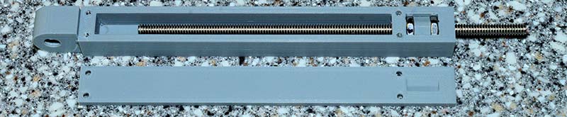
FIGURE 5. The inner tube of an actuator showing the two 10-24 nuts with a spacer in between, in a 12.5 mm slot.
The bottom of the slot is shaped for a hex nut. The two nuts are placed at opposite ends of the slot and a spacer inserted between them to keep them in place. When you insert the 10-24 threaded rod past the first nut, it usually will not engage the second nut.
By re-inserting the second nut after turning it 1/6 of a turn at a time, you’ll find one position where the second nut accepts the threaded rod.
It’s important that the spacer doesn’t fit too tightly into its position between the nuts or the threaded rod may jam.
This system of two nuts is often used to decrease backlash. A small spring can also be used between the nuts, but again it must not exert too much force on the nuts or they will jam. I couldn’t easily find a small spring that didn’t exert too much force, so I used the spacer.
I found I needed to sand the ends of the spacer slightly to get a perfect fit. With this system, the threaded rod is connected to the motor with a flexible coupling, with the Yellow Jacket motor supplying the bearing at the opposite end.
My final design used the Hall-effect sensor to find a home position and from then on, the encoders in the Yellow Jacket motors gave me the linear distance the actuator tube had traveled. SV
Article Comments