Is LiDAR in Your Robot’s Future?
By John Blankenship View In Digital Edition
LiDAR (Light Detection And Ranging) is finally becoming an affordable replacement for the IR and ultrasonic ranging sensors typically used on hobby robots. This series of articles will help you decide if LiDAR is in your robot’s future by exploring your options and even simulating a LiDAR point cloud, so you can experiment without purchasing hardware.
Mobile robots need some form of perimeter sensors to be aware of obstacles in their environment and to navigate through it. Simple infrared reflective sensors can provide proximity detection, but ranging sensors (both IR and ultrasonic) can provide much more information by not only detecting objects, but measuring the distance to them.
Ultrasonic Rangers
The wide beam of an ultrasonic ranging sensor such as the Parallax PING))) shown in Figure 1 can help to ensure that all objects are detected, but the wide beam also makes it difficult to isolate the distance to small individual objects that are clustered together.
![]()
FIGURE 1.
Infrared Rangers
The thin beam of IR ranging sensors such as the Sharp GP2Y0A21YK0F in Figure 2 (also available from Parallax.com) can isolate smaller objects by sweeping the beam horizontally in small increments. Unfortunately, IR sensors are generally severely limited in their maximum ranging distance.
![]()
FIGURE 2.
Laser Rangers
Replacing the IR beam with a laser can greatly increase the usable range, but we still need to scan the beam over the observed area. Typically, this is handled with a motorized turret that either moves the laser itself, or a mirror or prism that can redirect the beam.
The distance to objects can be determined by measuring the travel time for the reflected beam (referred to as time-of-flight), but greater accuracy can be obtained by also using triangulation which involves determining the reflection angle using a CMOS/CCD sensor array.
Because of these complexities, LiDAR units with reasonable data acquisition times have generally been very expensive, often extending to thousands of dollars.
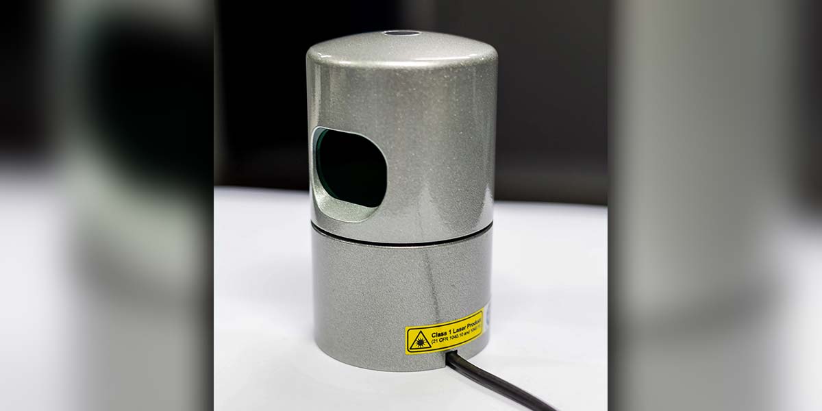
More recently, innovations in design and production have greatly reduced costs of laser-based units. LiDARs with sample rates and accuracies suitable for hobby robotic applications can now be purchased for less than $200. I personally backed a solid-state, 180°, 2D scanning LiDAR unit (see Figure 3) from a Kickstarter project to give me something to experiment with. I’m expecting delivery in a couple of months, so watch for a detailed review in a future article.
![]()
FIGURE 3.
Point Cloud Data
The raw information available from LiDAR hardware is generally just an array of distance information which is often called a point cloud. If, for example, your hardware performs a 360° scan and takes 360 distance measurements (one degree apart), you could store the measurements in a one-dimensional array composed of 360 elements. The angle associated with each reading can be inferred from the data’s position in the array.
A single horizontal scan of this sort is referred to as 2D LiDAR and is generally all that’s needed for the in-home navigation of a mobile robot. Robotic drones need much more information since they fly in a three-dimensional space.
A 3D scan can be performed by tilting the LiDAR hardware over a specified range and generating 2D scans for different planes. This article will only deal with 2D scans.
SLAM
Normally, using a LiDAR requires complex software (often called SLAM) to maximize the usefulness of the point cloud data. SLAM stands for Simultaneous Localization And Mapping. The software can build a map of the robot’s environment by stitching together scans taken as the robot moves about (similar to how a camera can take panoramic photos when you move it manually through a horizontal arc).
Localization allows the robot to determine its current position in the environmental map. This process involves comparing the expected scan data of all possible positions in the map to find one that best matches the robot’s current point cloud.
Algorithms for such a search can be very complex — especially if they utilize techniques to increase the efficiency of the search in order to reduce the total time required.
If you have an operational SLAM system, your robot can utilize path-planning software to analyze the environmental map and determine a series of movements that can drive your robot from its current position to any other position in its environment. This adds still another complex layer to the software needed to perform navigation with a LiDAR system.
Fortunately, there are some free LiDAR software components available, but it’s important to remember that when using free software you have to evaluate (often with minimal support) not only its suitability but also its reliability to meet your needs.
SLAM certainly provides elegant solutions for a variety of complex problems associated with autonomous navigation, and I certainly look forward to experimenting with it when I finally get my LiDAR hardware. While waiting for the Kickstarter project to conclude though, I started wondering if I could develop a less complicated way of utilizing the point cloud information to handle basic navigation for a hobby robot. I figured it had to be possible — especially if I was willing to make some compromises.
Compromises
The first of these compromises was to eliminate the need for the robot to be able to move from anywhere to anywhere in its environment. I reasoned that most hobbyists would be happy if their robot could reliably move between a number of fixed positions within their home.
This would allow them to tell their robot, for example, to come to the kitchen, and the robot would then find its way to a predetermined kitchen destination as long as it was currently located at one of the other predetermined positions.
Another compromise could be that the paths between predetermined destinations would also be fixed. This means that the point cloud data only has to be used to ensure that the robot can reasonably stay on a predetermined path. It turns out, this is not nearly as hard as you might imagine.
Think how you might find your way through your home if you got up in the middle of the night. Consider that even though you can’t see clearly in the dark, you should be able to make out general shapes. You might, for example, be able to determine areas where there are objects or openings. You might even be able to distinguish larger objects like a sofa from smaller things like a chair, as long as you’re already familiar with their general placement within the environment.
The point is, that if you’re walking through your own home in the night, you don’t have to be able to clearly see the sofa or the chair because you know where things generally are. If you know your initial movement should be toward the sofa, for example, you could just look for a large shape in the dark and move toward it.
As we will see, the size, position, and distance to various objects and openings are easily obtained from point cloud data. And, after a little experimentation, I found that using that kind of information properly can make it relatively easy to navigate between predetermined positions using a predetermined path.
Eventually, it will be nice to test these ideas with real LiDAR hardware, but I didn’t want to wait the months needed for the Kickstarter project to come to completion.
Furthermore, I figured there would be many readers that don’t currently own LiDAR hardware that might want to experiment with some of these ideas without having to purchase a LiDAR.
LiDAR Simulation
If you’ve read my articles in the past, you know I have an affiliation for simulation — especially with RobotBASIC (a language I give away free at www.RobotBASIC.org). Let’s look at how we can create a simulation of LiDAR hardware. The goal is to create a subroutine that, when called, will produce an array of point cloud data based on an on-screen environment.
If you had to do all the programming from scratch, this project would be a lot harder. Fortunately, though, RobotBASIC’s internal simulated robot has many integrated sensors, including a thin beam ranging sensor that measures straight ahead. All we have to do is rotate the robot through the desired range and take a distance reading with every degree of movement.
The program in Figure 4 shows you the basics of how this can be done. The main program establishes the maximum distance for the individual readings. For the simulation, the distance units are pixels, but you can think of them as inches based on the scale of the environment (the robot is 30 pixels in diameter).
main:
MaxDist = 190 // scan range
dim DistData[360] //scan data
gosub DrawEnvironment
gosub InitRobot
gosub PerformScan
gosub DisplayScan
end
InitRobot:
rlocate 400,300,90
rInvisible LightBlue
return
DrawEnvironment:
SetColor LightBlue
LineWidth 4
circle 400-MaxDist,300-MaxDist,400+MaxDist,300+MaxDist
SetColor Black
rectangle 130,200,270,240
circle 600,100,700,230
circle 300,400,450,450
rectangle 450,450,650,500
circle 300,200,400,250
rectangle 450,200,500,250
linewidth 1
return
PerformScan:
for a=0 to 359
d =rRange()+15 // make from center of robot
if d>MaxDist then d=MaxDist
DistData[a]=d
rTurn -1 // turn robot to next position
next
return
DisplayScan:
SetColor Green
for a=0 to 359
d=DistData[a]
A=dtor(a)
line 400+(20*cos(A)),300-(20*sin(A)),400+(d*cos(A)),300-(d*sin(A))
next
return
FIGURE 4.
The main program also creates an array for holding the scan data. Several subroutines are then called to draw the simulated environment, initialize the robot, perform the scan, and display the scan.
Refer to the PerformScan module to see how easy it is to acquire the point cloud data. A for loop turns the robot through a full 360° rotation (leaving it in its original orientation). The internal function rRange()measures the distance from the front edge of the robot to the nearest object directly ahead of the robot.
Notice that 15 (the simulated robot’s radius) has been added to the measurement taken to make it appear that the reading was taken from the center of the robot. The adjusted readings are stored in the array mentioned earlier.
Figure 5 shows the output from the program. The blue circle shows the maximum range of the simulated LiDAR. Notice that one of the objects in the environment is totally out of view. The green lines show the measured distances from the robot to the objects seen or to the LiDAR’s maximum range — whichever is smaller.
![]()
FIGURE 5.
What’s Next?
In the next installment, this simple program will be expanded so that it can report on the size and position of each of the objects found in the viewable area. That information will then be used to demonstrate how a robot can use it to navigate between fixed positions within its environment.
If I’ve piqued your interest, try experimenting with this problem on your own and compare your ideas to those I present in the next article. SV
Article Comments