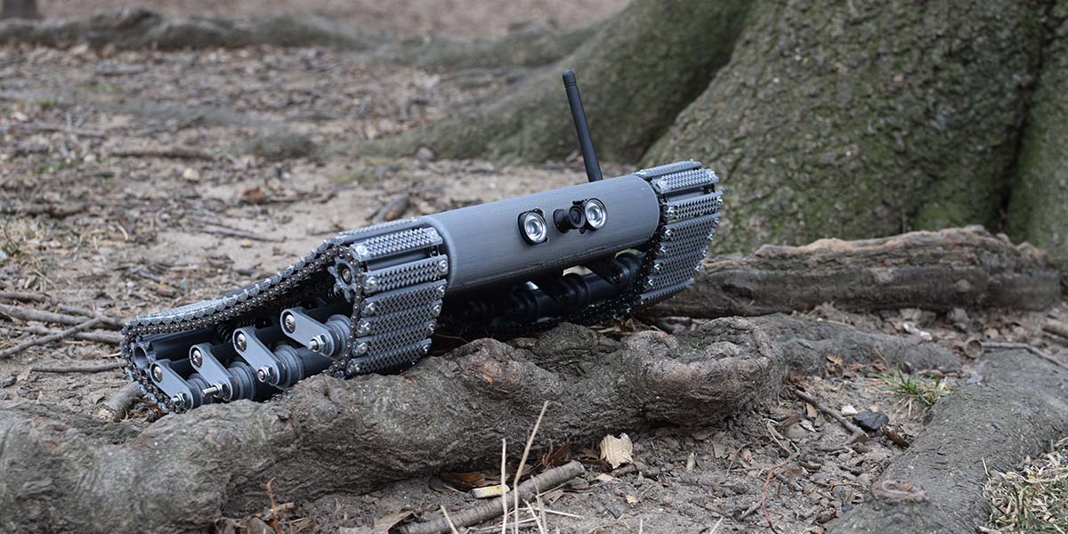
I Built a Military Robot
By Aviv Butvinik View In Digital Edition
Military robots are becoming increasingly common in the daily operations of armed forces around the world. These robots are ushering in a new generation of soldiers that will rely more and more on robotic intervention for the completion of dangerous tasks. For intelligence, surveillance, and reconnaissance (ISR) missions which rely on stealth, these devices are often surprisingly small for the purpose of avoiding enemy suspicion. Specialized gadgets like these are often priced in the tens or hundreds of thousands of dollars.
I set out to build a military surveillance robot of my own, just like the real ones! Could I do it with off-the-shelf hobby parts and a 3D printer?
I began the journey with three goals: the end product would be able to traverse the sandy hills of a desert environment; stream video to a main control unit during travel; and record video about enemy locations at night surreptitiously through a front mounted night vision camera.
As with any design project, I began by researching the existing market. I analyzed a multitude of military robots and their special features, paying close attention to their camera setups and means of mobility. These analyses were followed by concept design sketches and mechanical drawings to brainstorm the overall proportions and possible avenues of exploration. Take a look at Figure 1, Figure 2, Figure 3, and Figure 4.
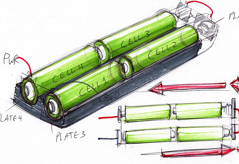
Figure 1 - Hand sketch of the 18650 Series battery pack.
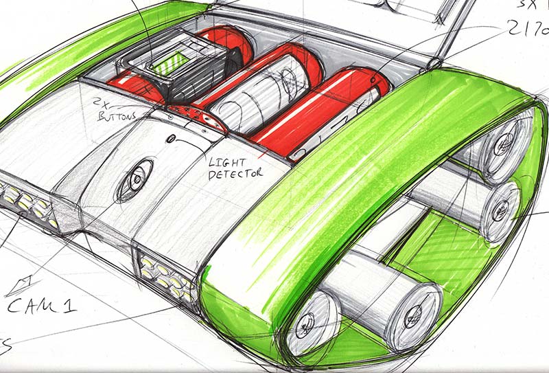
Figure 2 - Hand sketch of a robot concept (1).
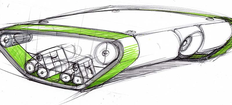
Figure 3 - Hand sketch of a robot concept (2).
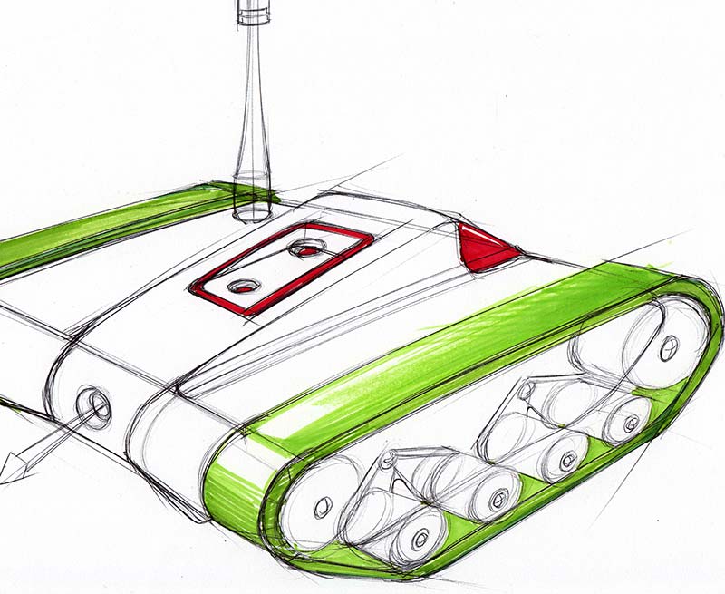
Figure 4 - Hand sketch of a robot concept (3)
Next, I considered the means of locomotion necessary for desert environments. I narrowed my search to military desert robots, noticing that most all of them have continuous treads surrounding two large sprockets in a “slot” shape.
The exceptions were the heavyweight robots that had a few other rollers along the base of the continuous tracks for extra support. This configuration was very simple and robust but provided little to no suspension. In the large rolling hills of the desert, suspension may not matter, but there are sections of desert with flat packed sand and small rocks which would wreak havoc on a slot loop.
The slot loop also doesn’t account for much climb. The angles associated with the fronts and backs of real tanks allow them to climb over large objects and keep rolling. Keeping in mind that the end result would need a strong suspension system with the ability to climb over small rocks and gravel (if necessary), I brought the focus to the tank treads themselves. What tread shape would be most appropriate for grip? What and how could tread loops be created with the resources I have? It was time to scour the Internet and begin prototyping to find the answers.
I set my sights on roller chain and 3D printed sprockets as possible motion components for continuous tread. Roller chain is the exact type of chain you would find on a bicycle, but I chose “#25 gauge” because it was the smallest fully metal ANSI size and thus the lightest. It would be made of shot-peened steel, capable of surviving the friction of the sand grains between its links, high desert temperatures, and high UV radiation.
I got a chain breaker and broke two loops with the same number of links on each. I held these loops together and designed horizontally-oriented 3D printed tread pieces that would fasten to the gaps in the roller chain links with small nuts and bolts. Since the screws were sticking out of the back sides of the chain loops, they would have interfered with an off-the-shelf sprocket.
To circumvent this issue, I made a dual-sprocket roller with every other sprocket tooth removed. This way, the screws would fit in the clearances of the gaps. Figure 5, Figure 6, and Figure 7 show the custom dual sprocket and motor.
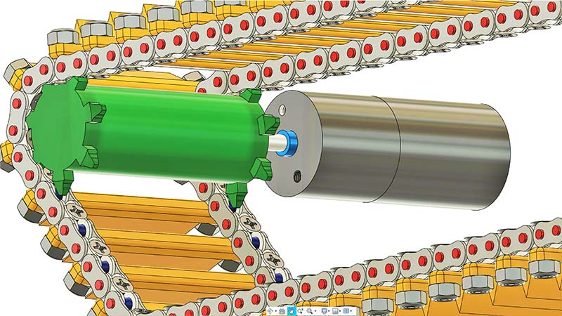
Figure 5 - Custom dual sprocket and motor driving the continuous roller chain tread.
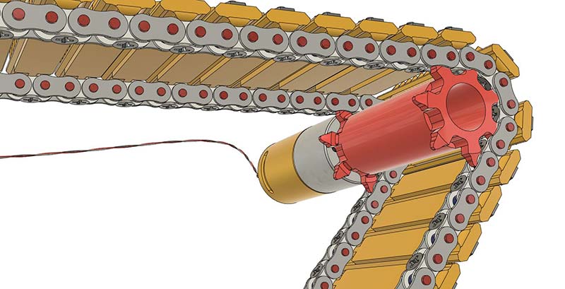
Figure 6 - Finished custom dual sprocket and motor driving the continuous roller chain tread.
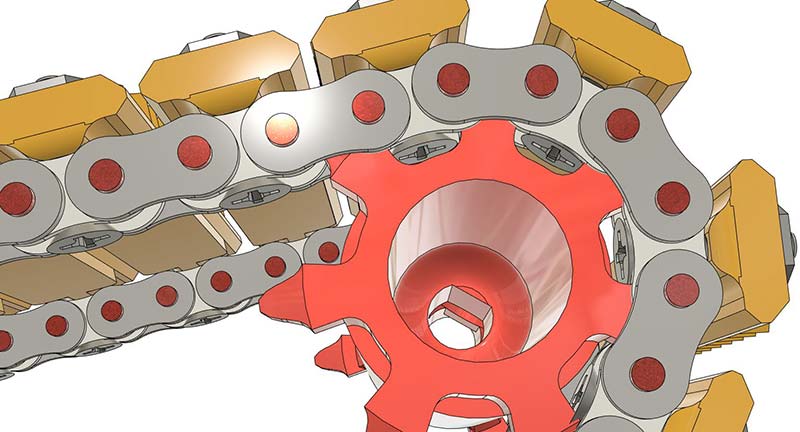
Figure 7 - Close-up of custom dual sprocket driving the roller chain.
With the chain belt fully assembled in a loop, I installed it on one side of the robot by fitting it over the dual sprocket attached to a motor on one side and the idler roller on the other. Since this would cover the top section of the revolving belt loop, it was time to theorize what type of suspension roller wheels along the base of the tread loop would be best for extra support.
I considered two sets of roller assemblies that would rotate on bearings, capable of applying downward pressure and support to the base of the chain. Likewise, they could rotate upward and hold the top part of the chain from drooping when going over large bumps. These roller assemblies would be shock absorber loaded.
Upon 3D printing the parts, installing the bearings to the rollers, and assembling them to the housing, I realized these roller assemblies would get “stuck” in the upper position if rotated past a certain angle. There were also issues with their rollers not spinning aptly because of a lopsided spin, only being supported by a bracket on one side. Refer to Figure 8, Figure 9, and Figure 10.
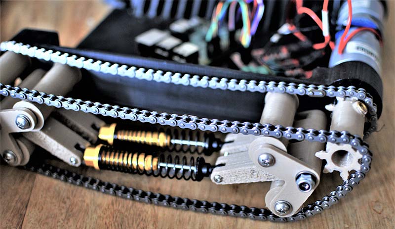
Figure 8 - Initial prototype with its many shortcomings.
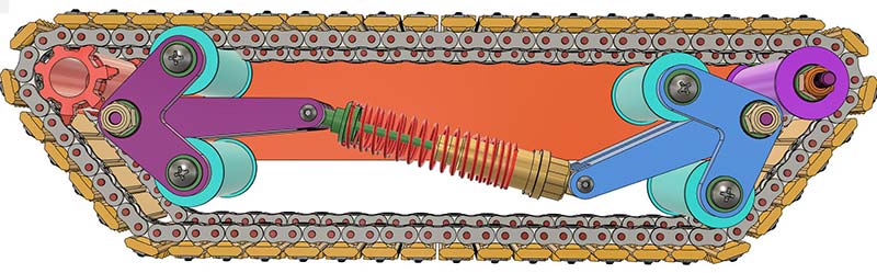
Figure 9 - Initial model showing the suspension issue (1).
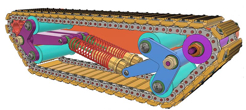
Figure 10 - Initial model showing the suspension issue (2).
Seeing all these issues, I decided to start from scratch with the lessons I learned, building a new suspension system where each arm is connected to its own shock absorber and the rollers are supported at both sides to promote a balanced spin.
The arms are attached to the housing through two ball bearings that fit in a hole in the housing wall. These act like sleeves, making it nearly impossible for the long bolts that hold them to waver. This perpendicularity will make or break the ability of the suspension arms to operate without rubbing against the walls of the housing. This proved to work quite well. The design is inspired from the “Christie Suspension.” The front two shock absorbers were oriented differently than the other three on each side to avoid interference with the drive sprocket. Refer to Figures 11A and 11B.
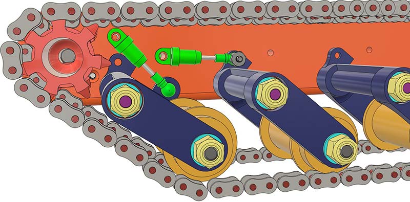
Figure 11a - Final suspension concept using dedicated shock absorbers for each roller.
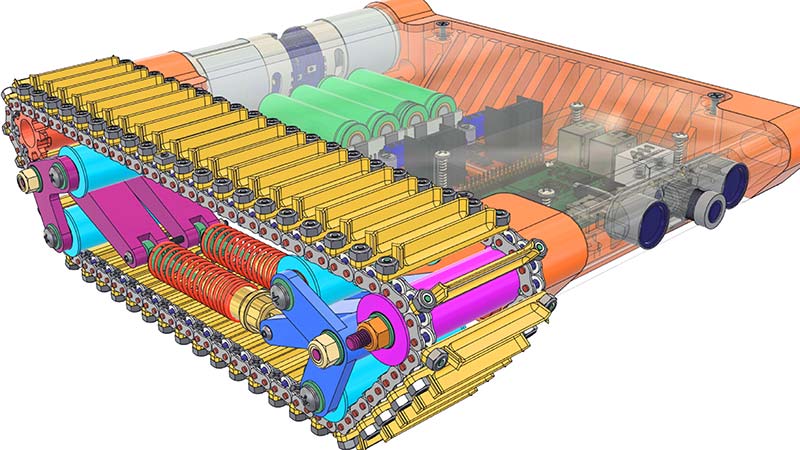
Figure 11b - Complete initial design with failed suspension concept.
The two DC motors chosen for this project were ServoCity 638286 premium planetary motors. I considered using economy motors at first but was drawn to the more than impressive stall torque and speed these could put out. I was able to get them second-hand, which is good because they were the costliest part of the project.
With these two large motors locked into the housing and inserted into the drive sprockets, I soldered some spare wire I had to the terminals on the motor with a dollar store soldering iron and wire. Not my proudest moment because this cheap wire adds unnecessary resistance to the motors.
I powered them up to test the suspension assembly using a DC power supply I had borrowed. Using a plastic cylinder, I pressed up against the floor of the suspension loop while it was running at high speed to see the effects of the suspension. Since the springs were weak, the assembly was very easily compressed. I ordered much stronger springs and replaced the springs on these tiny shock absorbers I ordered (1/24 scale hobby shocks). A simple calculation made it clear these would be able to hold the pounds the assembly would weigh. Take a look at Figure 12.

Figure 12 - Shock absorbers holding up the suspension in the final model.
I built the other side of the suspension the same as the first one and took a suggestion of using 18650 batteries to power this thing since 18650 batteries have no memory effect, can put out a lot of amperage, and are very compact. I was told I could use unprotected cells but opted for protected ones when I saw the danger they can pose. After all, these batteries are dangerous and proper care must be taken at all times when handling, using, and charging them.
Since these batteries had “nubs” at their tops as part of the protection system, I decided it would be best to make my own battery holder to be sure they would fit well (some 18650s don’t come out at the standard 18 mm by 65 mm size — especially when you opt for protected cells).
I designed my own battery holder in CAD with some open slots to fit the metal battery tabs. I 3D printed the result (Figure 13) and bought some off-the-shelf UXCell 18650 springs and tabs for them to act as the conductors.
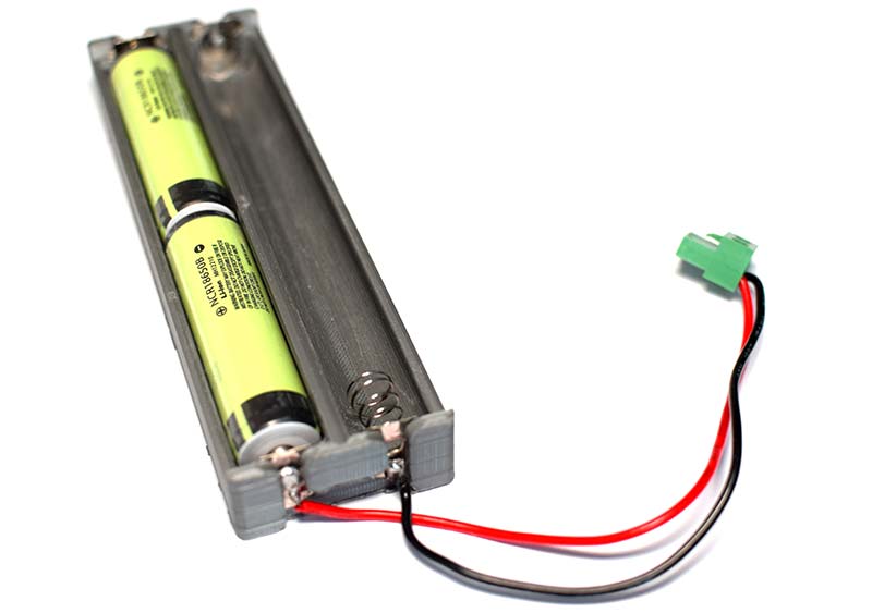
Figure 13 - 3D printed battery pack and pigtail with connector.
A friend soldered these contacts to connect them for me this time and they successfully held the batteries in series. Each battery gives out about 4.2V when fully charged and there were four of them. It sounds like this would be a lot of power for a 12V motor, but it wasn’t.
The double-edged sword of the protected batteries presented itself when the “power ceiling” of the batteries topped out at four amps. Once the four amp limit was hit, the batteries would shut down and the robot would halt. It would not be possible to reset them to work again without recharging them. I’m all for safety, but this was a bit of a ridiculously low value considering some 18650s can put out 20 amps with a single battery.
I scoured for motor controllers, checking in with an electrical engineer along the way for suggestions and tips. The XY160D by Drokking was a solid choice, as it used L298 logic — a popular standard in motor control with lots of support and documentation. I opted for a Raspberry Pi to be the brains because of its ability to interface with this chip, Wi-Fi controllers, and CSI cameras. Refer to Figure 14.
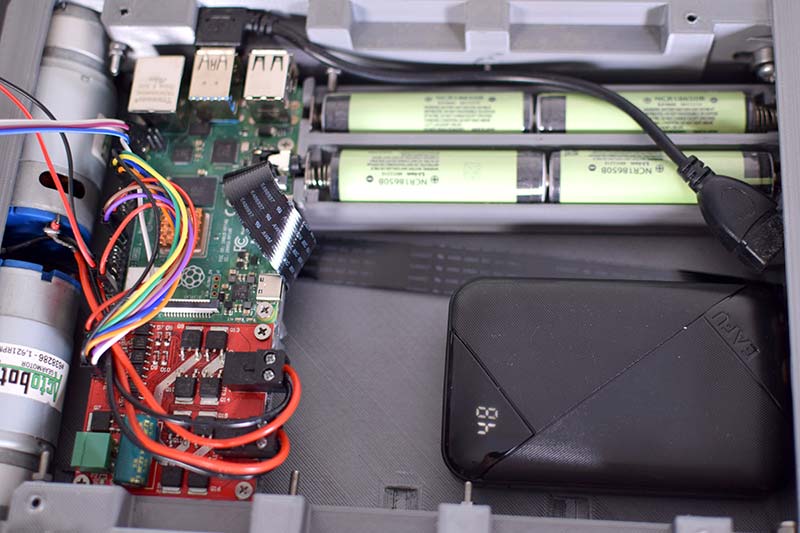
Figure 14 - Electronics assembly in the robot body.
I connected the Pi to the motor controller and the DC motors to the motor controller. The 5MP Noir CSI camera (Figure 15 and Figure 16).
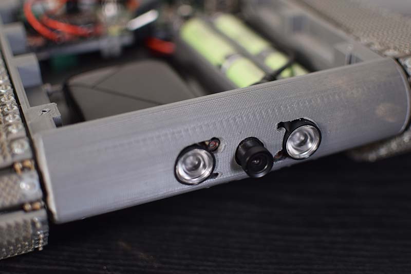
Figure 15 - Front mounted surveillance camera.
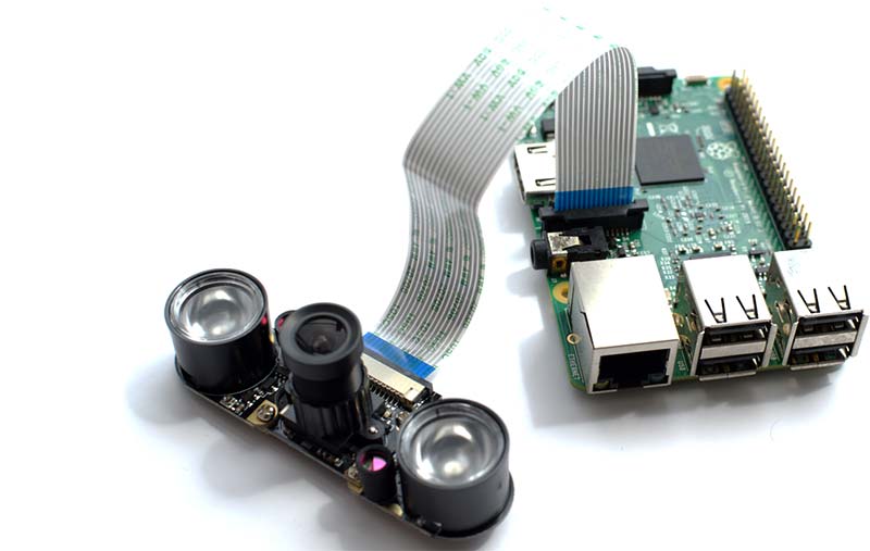
Figure 16 - The Noir surveillance camera hooked into the Raspberry Pi’s CSI slot.
I found online had two infrared emitters for night vision and were all powered from the ribbon cable to the Pi’s CSI slot. I had never really coded before, so I took an online course on Python for beginners to learn the basics. I don’t really recommend this because the course covered a lot of stuff not necessary in robotics.
The best resource I found for this project involved the Python GPIO library and how to use it.
I created code to call out the input and PWM pins I wanted to use to control the speed and direction of the motors. This code worked, but it was very annoying controlling the rover from code. One would need to type out and delete certain lines to make the robot go in a certain direction. I wanted to be able to control it using pushbuttons.
Enter Node-Red (Figure 17).

Figure 17 - Node-Red generated GUI for control of both motor’s speed and direction.
After having discovered this incredible resource, I was able to fairly easily code an online GUI with buttons that I could use by remoting into the RaspPi headlessly from a mobile device when it was inside the robot.
Using Node-Red, I coded out the high and low pushbutton commands to go to specific pins on the Pi, which would direct the motor controller to spin the motors in a given direction. I also set an adjustable PWM input which would allow for a specific speed, controllable through a percentage (0-100%) dial. These were made possible using the UI plug-in for Node-Red. On my cell phone, in this case, I could log onto a specific web address when connected (I put the Pi in access point hotspot mode) to access a web page with the GUI interface.
To extend the communication distance of the robot past the range the onboard Raspberry Pi Wi-Fi antenna provides, I added an external USB Wi-Fi dongle to the Pi. I learned the hard way that you need a RaspPi certified dongle to be able to set the Pi in access point mode with said dongle. Not any dongle can do this.
The dongle extended the range significantly and I was able to access the settings of Hostapd which let me do things like change the W-Fi protocol to be 802.11g instead of 802.11n to better suit long range connectivity. It even allowed me to choose what channel to use (among many other options in this tool). I found this to be very powerful and I was able to add Internet security features like encryption for a military feel.
For video streaming back to the cell phone, I used an existing software package which also called for connecting to the Pi’s Wi-Fi and going to a specific web address to see the stream. When logged into the Pi remotely, the sky is the limit. I streamed the video for convenience but was also able to record directly onto the SD card of the Pi by typing in commands to the terminal. I could type in these commands and then watch these video clips later at 1080p and 30FPS with no lag.
In a military environment, the robot could potentially send full recorded videos with no lag back to the robot controller using this feature. Streaming the video is very choppy — especially as the robot gets further and further away from the cell phone or tablet.
Finishing touches for this project included sand-proof gasketing for the housing’s top cover and cable management techniques within this housing. It would be possible to run all the electronics off the 18650 batteries with a buck converter when necessary, but the Pi requires consistent power so a separate 10,000 mAh USB power supply was used as a dedicated source. VR capability is possible now, as the video streamed to the cell phone can be placed into a Google cardboard or similar device. Figures 18-22 show various aspects of the finished robot.
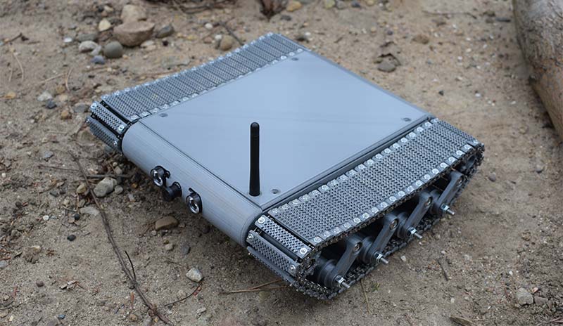
Figure 18 - The finished robot.
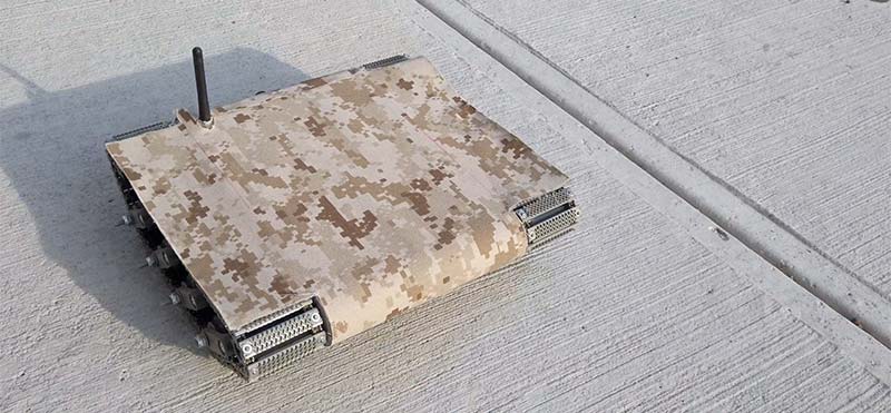
Figure 19 - The addition of camoflauge for low visibility from an aerial view (the top side shows almost none of the vehicle and the tracks still work with this material cover).
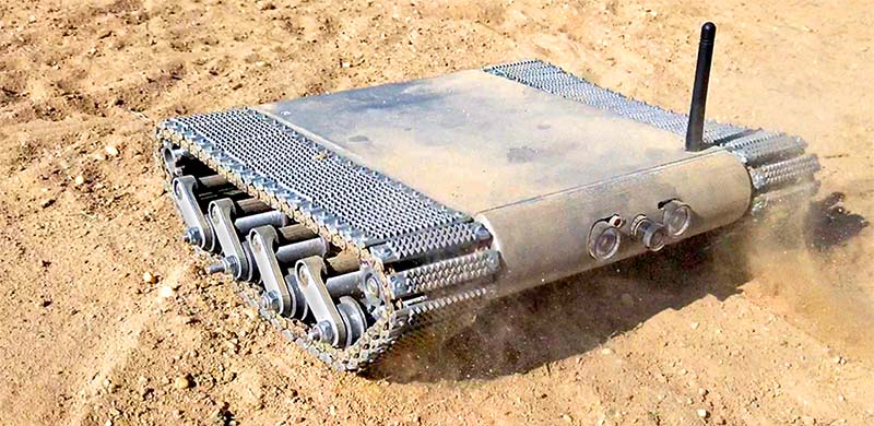
Figure 20 - The robot commandeering itself through sand.
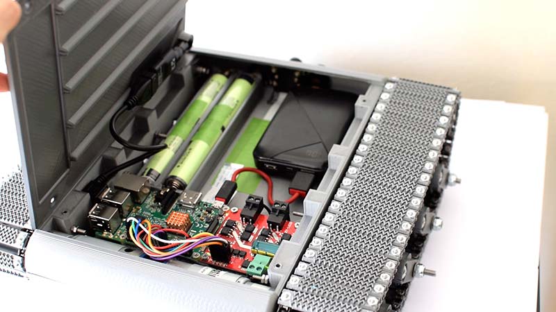
Figure 21 - Robot internals.
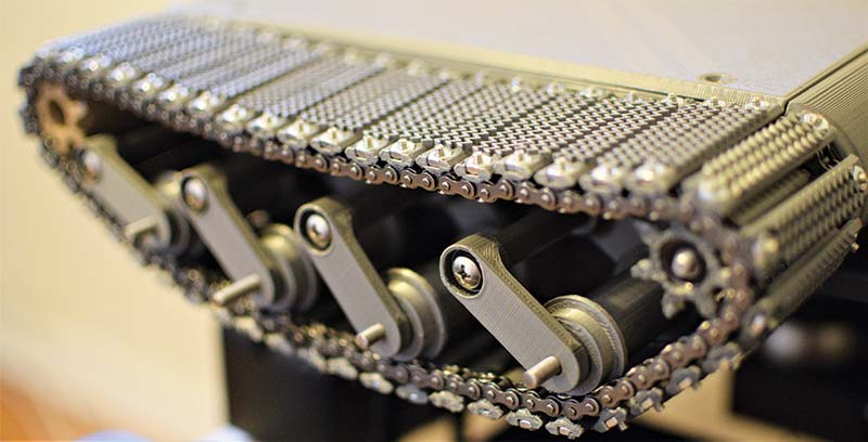
Figure 22 - Close-up shot of the final suspension.
In the future, I want to install and experiment with better camera options. The current camera doesn’t take insightful video in the darkness, and the placement of the IR LEDs wash out its ability to see past the distance of about a yard. Refer to Figure 23A.
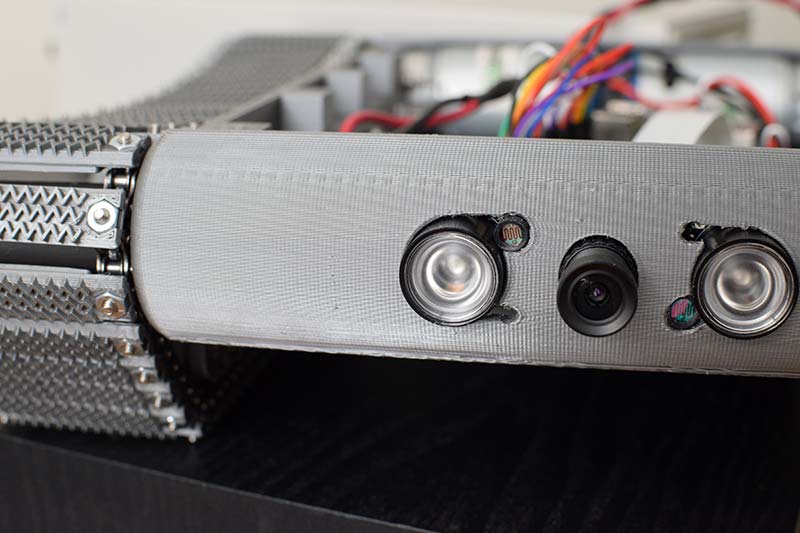
Figure 23A - Current camera setup on the robot.
This is a small lens that came with the camera which provides vision at about a 70 degree angle.
A major upgrade would be a zoom lens that has a larger viewing angle when zoomed completely out, and the ability to zoom in significantly and with adequate focus. These lens properties would be controlled through the use of a single stepper motor that rotates both the zoom distance and the focus. This problem of inadequate vision in the darkness of night is a major one, as it was one of the main project goals.
The plan is to utilize the same main sensor of the original camera module since it provides ample resolution, but to find a more suitable lens. Other upgrades may include the replacement or modification of the LED lights to shine in a straightforward direction away from the ground. Since the camera is very low to the ground to begin with, the light flooding this area is so bright it actually constricts its vision instead of aiding it (Figure 23B).

Figure 23B - Noir camera video in sand at night.
In addition to camera upgrades, it’s quite laughable to believe the military would use a cell phone to connect and control an ISR robot. A main control unit with ample battery power and high gain antennas is often used. This is an avenue I want to explore now that much of the robot assembly has been fleshed out.
My goal would be to create a handheld controller that’s ergonomic and compact, unlike many of the bulky controllers in large waterproof protective-cases being used today. In my research, I have seen controllers that are compact and that use existing gamepads, but these designs were much newer and may be part of an industry trend.
The last consideration that deserves some research is the tread pattern on each of the tread links. They have a triangular pattern that I believed could displace a sizable amount of sand while also allowing for a good sized surface area to stop the treads from sinking downward. I want to perform computational fluid dynamic tests in CAD to determine what shapes of patterns would be most advantageous for this use to be sure. Tests like these were put on hold to be able to focus on other areas of the project at the time.
All in all, this project was challenging and very rewarding to design and build. I hope you’ll check out its operation at the Engineering Juice YouTube channel.
I hope to implement some necessary upgrades to the system before I can really consider this to be a military robot. SV
PARTS LIST
- Night Vision CSI Noir Camera 5MP OV5647
- Raspberry Pi 4
- Motor Controller: DROK L298 XY-160D
- Motors: ServoCity 1621 RPM Heavy Duty Precision Planetary Gear Motor
- Protected 18650 Batteries: Panasonic NCR 18650B 3,400 mAh 4.9A - Protected Button Top Battery
- 18650 Battery Spring Contact Plates: Uxcell 20 Pairs 18650 Battery Negative to Positive Conversion Spring Contact Nickeling Plate 16.5 mm x 16 mm
- Power Bank: EAFU Portable Charger, Compact 10,000 mAh Dual 3A High Speed LED Display Power Bank
- Wi-Fi Antenna: Panda PAU06
Fasteners
- #25 Roller Chain: Red Boar Brand
- Connecting Links for Chain: Koch
- Chain Breaker: Ansoon Roller Chain Breaker Detacher Cutter for #25-60 Roller Chains
- 4-40 Hex Nuts: McMaster-Carr
- 10-32, 3” Screws: McMaster-Carr
- 10-32 Nut: McMaster-Carr
- #6 1/2 Flat Head Screws: McMaster-Carr
- M3 .5 Nut: McMaster-Carr
- 4-40 1/2” Flat Head Screw: McMaster-Carr
- M3 x 0.50 mm Thread, 50 mm Long: McMaster-Carr
- Flat Head Screws M3 x 0.5 mm Thread, 8 mm Long: McMaster-Carr
- Washer for Number 10 Screw Size, 0.203” ID, 0.438” OD: McMaster-Carr
3D Printing
- 3D Printer: Sovol SV01
- Filament: Overture PETG
WEB CONTROLLER USED
https://nodered.org
HOW TO USE THE GPIO LIBRARY
https://toptechboy.com/raspberry-pi-with-lesson-26-controlling-gpio-pins-in-python
HOW TO PUT A PI IN ACCESS POINT MODE
https://www.raspberrypi.org/documentation/configuration/wireless/access-point-routed.md
Official YouTube Channel — See this robot in action at Youtube.com/c/EngineeringJuice.
For the Official Video, see https://www.youtube.com/watch?v=5bgXjKqfwAk.
Article Comments