Hands-Free Robot Control
By Jim Newman View In Digital Edition
Ever since I first saw the Leap Motion hand tracking controller, I’ve been fascinated by the potential of what can be done with this amazing device. Leap Motion has not only developed a device that can track your hands, but through their software, they can tell you every characteristic about your hands. With great accuracy, they can tell you every aspect of your left, right, or both hands; they can tell you the pitch, roll, and yaw of the palm of your hand; they can tell you how many fingers you have extended, along with the length and direction of each segment of each finger on each hand (including your thumb). With this device and its accompanying software, you can use your hands as input devices to control any aspect that is controllable through your computer. The potential of this device is limitless!
With this in mind, I wanted to start with a simple device that can be controlled with just hand gestures. I’m doing this both to become more familiar with the use of the Leap Motion controller along with its software, and to just have some fun. What I came up with is the software that allows you to control a SparkFun RedBot robot with just your hands in free space.
The RedBot robot is a basic platform that has two wheels where each one is driven independently, along with a third pivot point. So, in order to control this robot, you’ll need throttle control for forward and reverse along with directional control for straight, left, or right. I decided to use a single hand to control the device with the pitch of the palm to control the throttle and roll for directional control.
So, how am I communicating with the RedBot? Good thing you asked! I just happened to have several Digi XBee wireless RF modules left over from an earlier project that fit the bill. The best part is that the controller board on the RedBot is already fitted with the proper connector to support an XBee module. I just love it when things work out for the better!
In addition to the one XBee module for the RedBot, I have two others. Both of these modules are mounted on SparkFun Explorer boards that include an FTDI-to-USB chip, so all you’ll have to do is plug the module into the Explorer board, then plug the Explorer board into an open USB port on your computer, and you’re all set.
Now, you may ask, why do I need two modules connected to my computer? Again, good question! We’ll be using one as a transceiver to communicate with the XBee module on the RedBot and the second one that will be used to monitor all communications between the computer and the RedBot through the use of a serial terminal window.
This article describes the required hardware and software that provide you with the ability to control a SparkFun RedBot using the Leap Motion controller. This article also contains the firmware that you’ll be loading onto the RedBot along with the application that you’ll be running on your host computer that allows you to control the robot without any contact to any device.
Hardware Requirements
The hardware requirements consist of the Leap Motion controller, the RedBot robot, a variety of Digi XBee modules, and the hardware to support those modules. These requirements are documented in the following sections.
Leap Motion Controller
The heart of this project is the Leap Motion controller shown in Figure 1.
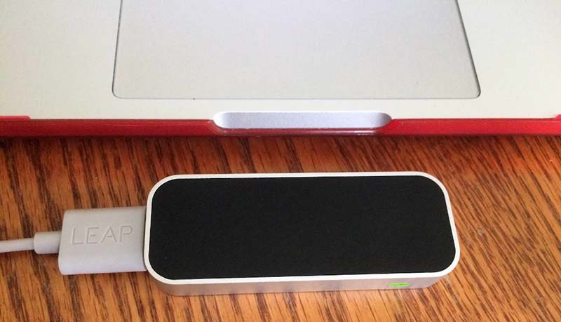
Figure 1 - Leap Motion controller.
This is the device that will track the movements of your hands and turn those movements into a format that you can use in your program to manipulate anything else that is controllable through your computer. Leap Motion provides the hand tracking controller along with a USB 3 cable.
We’ll get into the details of connecting the controller to your computer and configuring your computer to be able to interact with this device a little later.
SparkFun RedBot
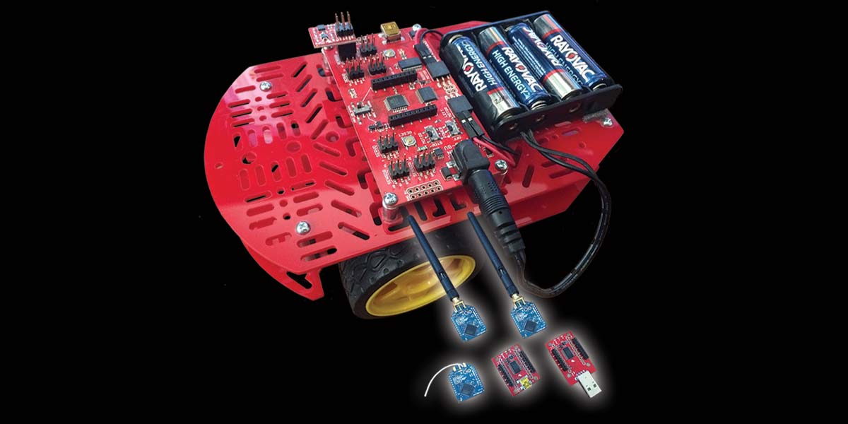
Next, we have the RedBot development platform. This kit comes with everything shown in Figure 2 (along with a few items not shown).
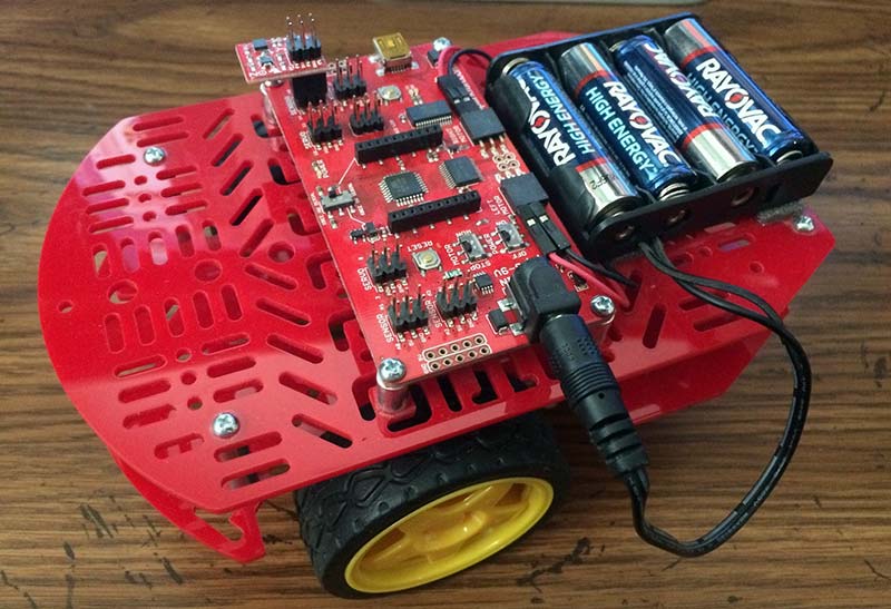
Figure 2 - SparkFun RedBot robot development platform.
Please be aware that this particular version of the RedBot is no longer in production. However, the good news is that the differences between this RedBot and the one currently being sold by SparkFun have no relevance to what we will be doing in this demonstration.
The best part of this platform is the RedBot Mainboard that is mounted on the top of the robot. This is an Arduino compatible development board that includes everything that’s needed to control this platform, including the motor drivers. It also includes multiple I/O ports that can be used to drive servos or other devices, along with monitoring sensors.
The best part, however, is that it comes with the proper connector for the Digi XBee module that we’ll be using to remotely control the robot. In this project, we’ll utilize the Digi XBee connector along with the motor drivers. Plus, with all of that available I/O, there’s lots of room for expansion!
The first thing you’ll need to do is build the RedBot according to the instructions provided by SparkFun. This is an easy and fun process and shouldn’t take more than an hour or so to complete.
Digi XBee Modules
The last pieces of hardware that we’ll need are the items shown in Figure 3. What you see are three Digi XBee Pro 900 modules along with two versions of the SparkFun XBee Explorer USB boards. I have one XBee module that is using a wire antenna and two that are using the RPSMA connector with a 900 MHz antenna attached to each.
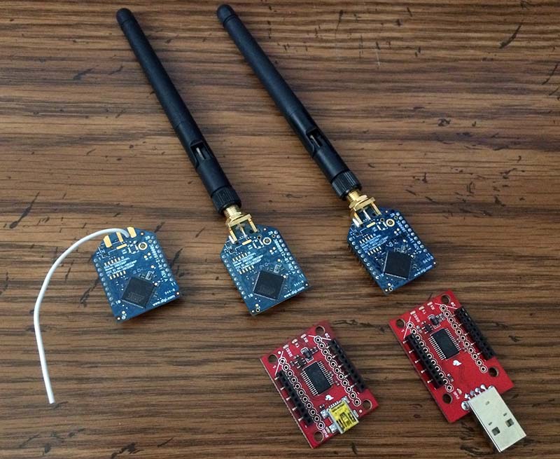
Figure 3 - Digi XBee Pro 900 modules.
For this project, either antenna configuration will work. As for the Explorer boards, one needs to be plugged into a USB cable whereas the other can be plugged directly into a USB port on your computer. Again, either will work; the choice as to which one to use is up to you.
I’ve chosen the Digi Pro 900 modules primarily because I had these left over from an earlier project. These modules work on the 900 MHz frequency band as opposed to the Digi modules that you’ll normally find that work on the 2.4 GHz frequency band.You’ll need to attach one XBee module to the RedBot Mainboard’s XBee connector and mount the other two XBee modules to the Explorer boards as shown in Figure 4.
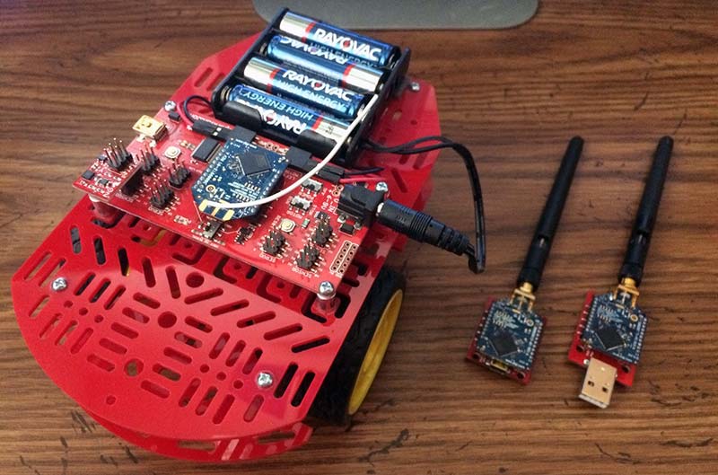
Figure 4 - RedBot and XBee modules.
Please be aware that there is what I’ll call a ‘design oversight’ with the RedBot Mainboard. This has to do with the placement of switch S3. During development, you’ll need to change the setting on this switch in order to load the firmware onto this board and then change the setting back in order for the firmware to work properly. That’s why I’ve shown the XBee module with the wire antenna mounted on the RedBot. With this XBee module, you’ll have direct access to switch S3 without having to remove and then remount the module during firmware updates.
As a further note, I’m showing two XBee modules that will be used on the host side, when in reality, you only need one. The second module will be used to monitor the serial data between the RedBot and the host computer.
This makes debugging the software much easier and is well worth the cost of the additional module when you consider the time that will be saved.
Another item that I need to inform you about is that Digi supplies a very good tool for configuring their devices called XCTU. This setup tool provides you with the ability to upgrade your XBee devices to the latest firmware. It also allows you to configure the devices to use a baud rate other than 9600 bps which is their default value.
I’ve reconfigured mine to use 115200 bps which is what the firmware for the RedBot and application is expecting. You’ll either need to reconfigure your XBee devices to use this baud rate or modify the supplied code to use 9600 bps.
Software Requirements
There are multiple pieces of software that will need to be downloaded and installed. These include the Arduino integrated development environment (IDE) along with the SparkFun plug-in for Arduino, Microsoft Visual Studio Community 2017, git, Leap Motion Services, and LeapC-Sample. You will also need to retrieve the software that I developed for this project from the article downloads. Details on where to get and how to install the various software packages are listed next.
Microsoft Windows 10
I guess that I should start with the basics. All development was done using Windows 10. It should be possible to port everything to either MacOS or Linux, since most of what is described here does have support for those operating systems.
Arduino IDE
Let’s begin with the simple stuff first. You’ll need to install the Arduino IDE. At the time of this writing, I installed version 1.8.7. Once you have this installed, you’ll need to install the SparkFun plug-in for Arduino.
This is a pretty straightforward process and is well documented on the SparkFun website. You can start by going to https://learn.sparkfun.com/tutorials/experiment-guide-for-redbot-with-shadow-chassis/experiment-1-software-install-and-basic-test.
Then, just follow the instructions on how to install the Arduino IDE along with the SparkFun plug-in.
Truthfully, they’ve explained the process better than I can.
Visual Studio Community 2017
Visual Studio Community 2017 is a full featured and free version of Microsoft’s Visual Studio IDE. You can download the installer for either Windows or Mac at https://visualstudio.microsoft.com/vs/community. Once you’ve downloaded the installer, you’ll need to execute it to install Visual Studio on your system.
git
You first need to install git. git is required in order to clone the various repositories that are required to build the firmware for the RedBot and to build the application program. To help you out, go to https://git-scm.com for links to everything that you’ll need to get going.
I’m a big fan of configuration management, so I consider learning git to be very important in anyone’s growth as a software engineer.
Leap Motion Services
Another piece of software that you’ll need to install is the Leap Motion Services. Leap Motion does a great job at defining how to install their services at https://www.leapmotion.com/setup.
For this project, you’ll need to install the Leap Motion Services for the desktop. Once installed, the service will run in the background and will only become active once the Leap Motion controller is plugged into your host computer.
The application that we’ll be building that runs on the host computer will interact with this service to get the hand tracking data. So, it’s quite important that it’s installed and working properly.
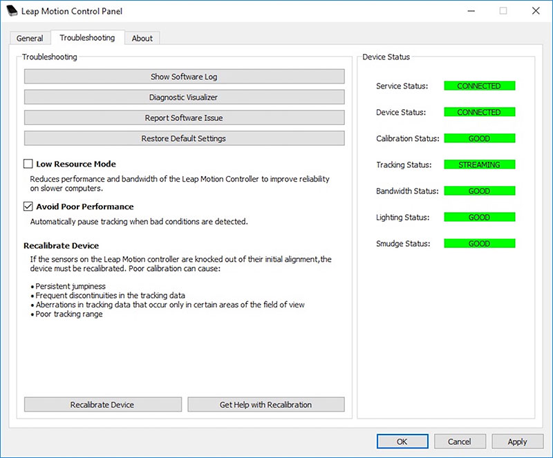
Figure 5 - Leap Motion control panel.
Once you have the Leap Motion Services installed, we can verify that the host computer can see it and that it is functional. Leap Motion supplies a USB 3 cable with their controller, so start by plugging the controller into the USB 3 Micro-A end of the cable and then plug the USB 3 Type-A connector into an open USB port on your host computer.
This does not necessarily require that the host computer have an open USB 3 port since a USB 2 port will work as well.
Next, you’ll need to bring up the Leap Motion Control Panel. You can access this from the hidden icon pop-up within the Windows Taskbar or by searching for Leap Motion Control Panel from the task bar as well.
Once the Leap Motion Control Panel is open, click on the Troubleshooting tab and you should see what’s displayed in Figure 6.
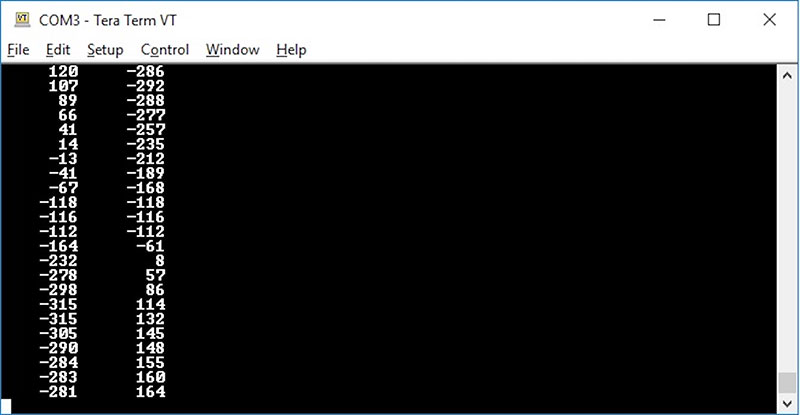
Figure 6 - Serial output to Tera Term.
First, check the Device Status panel. If everything is green, then we’re good to go. If you truly want to see what this device is capable of, click on the Diagnostic Visualizer button and have some fun.
Leap Motion LeapC-Samples
Please bear with me, we’re getting close to the end. The next software package that needs to be downloaded is the Leap Motion LeapC example programs that I used as a starting point for this project.
You’ll first need to go to the Leap Motion Github LeapC-samples repository at https://github.com/leapmotion/LeapC-samples.
If you have git installed (as I suggested earlier), all you’ll need to do is clone the repository. To do this, first bring up a terminal window and enter the following commands:
mkdir Development
cd Development
git clone https://github.com/leapmotion/LeapC-samples.git
In truth, you probably didn’t need to go to github to clone the repository. However, it’s nice to see what’s there and available for you to use.
redbot-hands-free-control
Last but not least, you’ll need to clone my github repository as well:
git clone https://github.com/JimInCA/redbot-hands-free-control.git
I know this was quite a bit, but this should be it for software installation.
Next, we need to configure the software by copying some code from LeapC to our project.
Software Configuration
Now that we have everything we need to build both the firmware for the RedBot and for building the host application, we now need to copy some files from the Leap Motion LeapC samples directory to our application directory. I’ve put together a batch file that will automatically copy the files from the LeapC-samples directory and place them where Visual Studio expects them to be.
Assuming that you cloned the two directories as defined above, this is all you should need to do:
cd redbot-hands-free-control
auto_config.bat
Please take note of the message that gets displayed after the batch file executes. You’ll need to make a minor edit to one of the files that got copied. This is necessary for the application to build properly; otherwise, you’ll get a message about a missing header file.
If you’re like me and prefer to use a bash shell, I’ve also provided a script to copy the required files. The advantage of this script file is that it uses sed to automatically update the file that needs to be modified. It’s a shame, but sed is not available under Windows.
Building and Installing the RedBot Firmware
Now that all the work is done, we can finally start to have some fun! To begin with, we’ll first build the firmware that we’ll load onto the SparkFun RedBot. This should be a simple task if the Arduino IDE is set up as defined previously.
Open the Arduino IDE and from the File menu, select Open. Once the file browser opens, make your way to <path>/redbot-hands-free-control/redbot-firmware and select `redbot-firmware.ino’ to open the file that has the firmware source code.
Please feel free to scan through the code to become familiar with what it’s doing. The code is very simple in that the setup() function initializes the UART and timeout counter. The main work is being done in the loop() function in that it waits for data to show up on the UART, reads the data, and then programs the left and right motor with the data that it receives.
If you look closely, you’ll also notice that I have a timeout counter that is intended to prevent the robot from running wild if it stops receiving data by zeroing out the motor analog values.
Now what we need to do is connect the RedBot to the host computer through the USB cable connected to the RedBot Mainboard. You should be familiar with this if you went through the SparkFun Software Initialization Guide mentioned earlier.
Once the RedBot Mainboard is connected to the host, you’ll need to open the Tools menu in the Arduino IDE and then scroll down to Boards. From the pop-up listing, scroll down and select SparkFun RedBot.
You will then need to repeat the process of opening the Tools menu, but this time, you’ll need to select Ports and then select the proper port that your RedBot is connected to on your computer.
From this point, it should be a simple matter of selecting Verify/Compile from the Sketch menu. Once it completes, select Upload from the Sketch menu to load the firmware onto the RedBot Mainboard. Please remember that you’ll need to change the position on switch S3 to upload the firmware and then switch it back to its original position once the firmware has completed uploading.
Building the RedBot Host Application
All that’s left to build is the application that will run on your host computer that will send the wireless commands to the RedBot by monitoring your hand movements using the Leap Motion controller.
We’ll start by bringing up the Visual Studio Community IDE and opening up the solution file for the application. Once Visual Studio is up and running, go to the File menu, scroll down to Open, shift right to open the sub menu, and select Project/Solution.
From the pop-up file browser, make your way over to the solution file <path>/Development/redbot-hands-free-control/redbot-application/redbot-application.sln, select this file, and then press the Open button. If all goes well, Visual Studio will open up the solution file for this project.
All you should need to do now is select Build Solution from the Build menu and Visual Studio will compile, link, and store the application executable in the ./x64/Release directory.
Testing Leap Motion Control of RedBot
Now it’s really time to start having some fun by getting the software and hardware talking to each other. The first thing that we want to verify is that our application can connect to both the Leap Motion controller and to the XBee RF module.
Start by connecting the USB cable to both the Leap Motion controller and host computer. Next, plug one of the XBee modules into the SparkFun USB Explorer board and then connect the board to a second USB port on your host computer. With everything plugged in, you’ll need to find out the serial port being used by the XBee module which can be done through Window’s Device Manager.
Once you have all of this done, you can enter the following on a command line replacing the serial port that I have shown with the one that you found in Device Manager. You can also specify a baud rate other than the default value used by the application:
<path>\redbot-application>./x64/Release/controller.exe -p COM4 -b 115200
Successfully connected to UART on port COM4 at baud rate 115200.
Successfully connected to Leap Motion Controller.
Using device LP95554261956.
If everything went well, then it’s time to see if our application is sending out any data. We’ll do this by connecting the second Digi XBee to your host to monitor the proper RF frequency for all data (or you can connect the second XBee module on a second computer if you like). You’ll then need to open a terminal program and connect this program to the second XBee module’s serial port. Both Tera Term and HyperTerminal work well for this, or you can use any other serial terminal that you prefer.
If everything is working, you should see the data that’s being sent from our application by means of its XBee RF module as shown in Figure 6.
Remember, we want to verify that the Leap Motion controller is the source of the data being sent! So, hold your left hand about 12 to 18 inches above the controller and verify that the data being presented in the serial terminal follows the movement of your hand.
If you hold your hand flat, the pair of data (the analog value for left and right motor) should be close to zero. Then, try tilting the palm of your hand forwards, backwards, to the left, and to the right (±pitch and ±roll). The data should change as you move your hand. Now for the ultimate test: It’s time to power-up the RedBot!
On the RedBot Mainboard, set the motor switch, S2, to the on position. Turn on the RedBot Mainboard by sliding S1 to the on position. For the first test, I’d set the RedBot on its end so that the wheels are in the air, and then place your left hand over the Leap Motion controller and verify that the wheels turn in the correct direction following the movement of the palm of your hand.
Once you’re satisfied that everything is working correctly, place the robot on a large flat surface and enjoy!
About the Magic
The real power in this application is what’s hidden inside the libraries supplied to us by Leap Motion. What they provide is a very simple set of APIs to get access to the hand tracking data. We then use that data to control the movement of the robot.
Here is the heart of the application code that gets the information from the controller that we use to determine the pitch and roll of the hand. We then translate that information into forward or reverse throttle and left or right direction.
Once we’ve calculated the proper values for the left and right motor, we then send that data to the RedBot by way of the XBee RF module:
while(1)
{
LEAP_TRACKING_EVENT *frame = GetFrame();
if(frame && (frame->tracking_frame_id >
lastFrameID))
{
lastFrameID = frame->tracking_frame_id;
for(uint32_t h = 0; h < frame->nHands; h++)
{
LEAP_HAND* hand = &frame->pHands[h];
LEAP_VECTOR* vector = &hand->palm.normal;
if (hand->type == eLeapHandType_Left)
{
// pitch will be used for throttle
// forward or reverse
pitch = get_pitch(vector) + (float)90.0;
pitch *= GAIN;
// roll will be used for turning left
// or right
roll = get_roll(vector);
roll *= GAIN * (float)0.5;
// calculate values for left and right
// motors
int32_t left_motor = (int32_t)(pitch -
roll);
int32_t right_motor = (int32_t)(-1.f *
(pitch + roll));
sprintf(str, “%8d %8d\r\n”, left_motor,
right_motor);
WriteFile(uart,str,(DWORD)strlen(str)
,&num_written,NULL);
}
}
}
} //ctrl-c to exit
This just scratches the surface of what you can do with the Leap Motion controller. The library not only provides data about the palm of your hand, it can also tell you about each finger, such as length and direction of each segment and for both left and right hands. The possibilities are endless.
Conclusion
That wraps up this introduction into using your hands to control your robot using the ultimate geek toy: the Leap Motion controller. I hope you have as much fun with this device as I did in developing this project. SV
Resources
Leap Motion Setup Guide
https://www.leapmotion.com/setup
Leap Motion LeapC-Samples
https://github.com/leapmotion/LeapC-samples
RedBot & Application Code
https://github.com/JimInCA/redbot-hands-free-control
SparkFun RedBot Products
https://www.sparkfun.com/catalogsearch/result/?q=redbot
SparkFun Software Installation Guide
https://learn.sparkfun.com/tutorials/experiment-guide-for-redbot-with-shadow-chassis/experiment-1-software-install-and-basic-tes
Digi XBee XCTU Setup Tool
https://www.digi.com/products/iot-platform/xctu
Microsoft Visual Studio Community 2017
https://visualstudio.microsoft.com/vs/community
git Installation
https://git-scm.com
Article Comments