Hacking an RC Car with the Mentor’s Friend
By Dane Weston View In Digital Edition
I designed a kit for Nuts & Volts (SERVO’s sister publication) that implemented a version of Jeff Ledger’s open source Pocket Mini Computer. It’s a Propeller based retro computer that emulates those early 1980’s classic computers you hooked to a TV and programmed in BASIC. The kit was aimed at parents and grandparents who wanted to share a technology experience with youngsters, but were a bit uncomfortable with learning the Arduino, Raspberry Pi, or other current platform. We called the kit the “Mentor’s Friend” and nicknamed it the “Amigo.” This article introduces the Amigo to SERVO readers and presents a simple computer-controlled hardware project (hacking a toy RC car) that you and a budding roboticist can build and explore together.
Figure 1 shows the completed Mentor’s Friend which uses the amazing Parallax Propeller P1 chip to provide all the I/O for the little retro computer, plus a tinyBASIC interpreter with 4K of program memory.
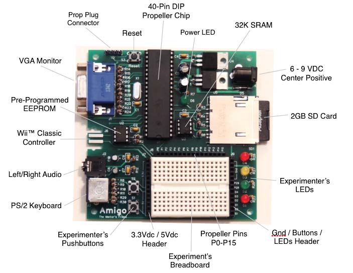
Figure 1. The Build-It-Yourself Mentor’s Friend. Just add a VGA monitor, PS/2 keyboard, and a small DC supply for loads of “old style” computer fun!
The Amigo Color BASIC interpreter is indeed tiny — integer arithmetic only; no support for strings; no arrays; no explicit DATA statement. However, it contains everything you need to introduce programming fundamentals to youngsters, without the instructional distractions of separate IDEs (integrated development environments), compilers, and other complexities.
One advantage of BASIC is that many would-be mentors can still find their way around in that “days of yore” language, regardless of their current microcontroller fluency, and Nuts & Volts has offered a series of articles on Color BASIC to help mentors easily explore programming fundamentals with their young protégés.
In addition to a simple introductory programming platform, the Amigo provides direct program control over 16 Propeller I/O pins, with a small breadboard and some LEDs and switches onboard to make that useful. These features make it easy to explore simple computer-controlled hardware projects directly from BASIC in one self-contained build-it-yourself package.
In this article, we’ll build a daughterboard “shield” for the Amigo, and use those hardware-control features to drive a toy RC car from the Amigo keyboard.
One year before the holidays, I noticed various radio controlled toys on sale at my local drug store. My first thought was — of course — I wonder if I could interface these to the Amigo? At the bargain basement price of less than ten bucks each, I couldn’t resist. So, I picked up a couple of RC toy cars and added “remote control car” to my list of potential Amigo projects.
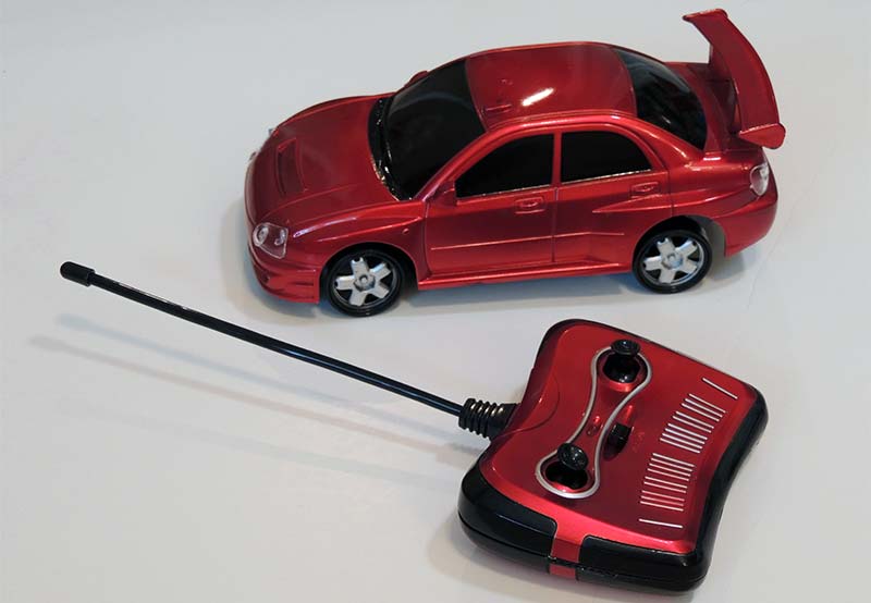
Figure 2. Typical toy RC car and controller. The Forward/Reverse and Left/Right controls operate pairs of SPST switches which are easy to interface to the Amigo.
When I started the “toy car” project, the first thing I checked was the controller. As I suspected, the forward/reverse/left/right controls were simple switches actuated by the controller joysticks (see Figure 3).
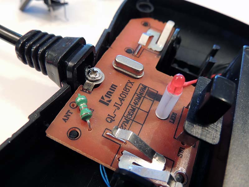
Figure 3. Inside the RC car controller. The plastic control sticks have been removed to show the SPST switches for Forward/Reverse and Left/Right.
I began examining ways to close those switches under Propeller I/O pin control. I had some small mechanical relays on hand, but most couldn’t be driven directly by an I/O pin.
I also had a bunch of different transistors available (my collection actually dates back to the 1960s, thanks to some I inherited from my dad), so a simple transistor switch arrangement seemed promising, and that’s where I began my search for an interface solution.
Finding an effective transistor switch to shunt the controller mechanical switches proved more difficult than I expected. Without going into needless detail, the transistor bias arrangements that worked often had unintended effects, like turning on the controller power indicator when the power switch was off. (I know, a real head scratcher, and one that I couldn’t figure out.) To further complicate things, controllers from different manufacturers were completely different, so transistor bias arrangements were not transferable one to another. Clearly, I needed a different approach.
Enter the TLP222AF solid-state relay. When my transistor-based approach fizzled out, a quick Internet search pointed to a more modern alternative: the optically coupled MOSFET solid-state relay. A browse through the many options available led me to the TLP222AF: a four-pin DIP IC which uses an internal LED to switch loads up to 500 ma.
As shown in Figure 4, the TLP222AF interfaces cleanly with a Prop I/O pin with nothing more than a current-limiting resistor — no muss, no fuss, and no transistor bias calculations or leakage current.
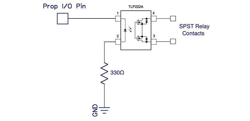
Figure 4. The TLP222AF solid-state relay offers a simple way to convert a Propeller I/O pin signal to an isolated switch closure — perfect for interfacing with the RC controller.
To implement a four-relay controller interface, you have a choice: either build the circuit directly on the Amigo breadboard; or construct a little “shield” board that plugs into the breadboard headers. If you’re just going to do a temporary “proof of concept,” the breadboard approach will work just fine. However, if you want to show off your car-driving Amigo in the future or use this approach for your own computer-controlled hardware project, building a shield board is the way to go.
Figure 5 shows how I implemented the circuit in Figure 4 on the Amigo breadboard, with one relay for each of the four switches in the toy car controller.
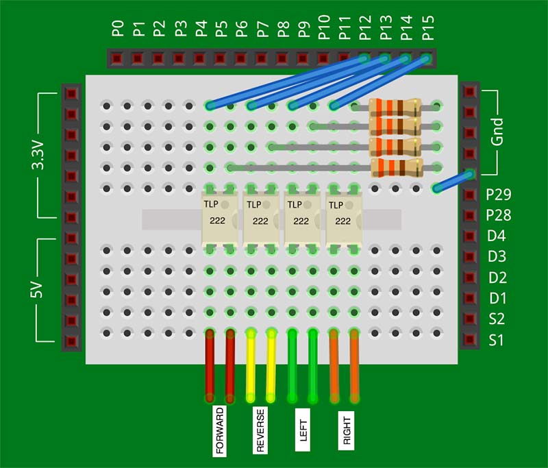
Figure 5. The Amigo/RC car controller interface using the TLP222AF. Validate the interface to your controller with just one relay before you lay in the other three.
Make sure you align the relays properly. Pin 1 (indicated by the little dot) goes to the 330 ohm resistor and on to ground. You may want to build things one section at a time and test it with your controller before you build out all four sections on the breadboard. Also, the I/O pin assignments are flexible; those shown in Figure 5 will match the software assignments in the article.
To build a shield board, you’ll need a Parallax EDU circuit overlay board (P/N 32999), four TLP222AFs, four 330 ohm resistors, an eight-pin female SIP header (optional), and some hookup wire. The circuit overlay board kit from Parallax includes the male headers that go on the underside of the board to connect with the Amigo breadboard headers.
Component layout is not critical; just be sure to get them on the “component” side — the opposite side from the male headers. Also, any resistor in the neighborhood of 330 ohms should work. I used 470 ohms with no problems.
If you're using Figure 5 as a guide for the component layout on your shield board, note carefully that the labeling on the TLP222AF chips is shown upside-down for readability in the figure. Make sure to align the relays with the “dot” connected to the Prop I/O pin.
You may want to double-check your layout against Figure 6 before you solder everything down.
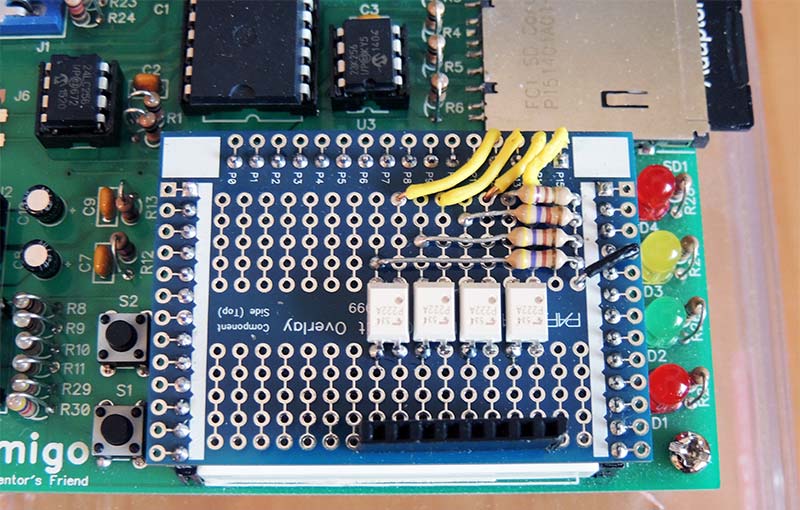
Figure 6. My build of a four-relay “shield” board for the Amigo, installed in the breadboard headers. It uses TLP222AF solid-state relays on the Parallax EDU circuit overlay board. Component layout is not critical.
Once everything is complete, plug your shield into the Amigo breadboard headers (this may take a little jockeying the first few times) and validate the functionality of each relay with a multimeter and the following code:
10 REM *** RELAY.BAS ***
20 INPUT “Propeller I/O Pin? “; p
30 PRINT “Toggling Pin “; p
40 PRINT “Press Any Key to Quit.”
50 OUTA[p]=1
60 PAUSE 250
70 OUTA[p]=0
80 PAUSE 250
90 IF INKEY=0 THEN GOTO 50
100 OUTA[p]=0
Once your four-relay circuit (either breadboard or shield) is good to go, it’s time to connect it to the RC car controller. Again, you have a choice in your implementation; this time, choosing to wire directly from the controller switches to the relay circuit, or installing a connector in the controller and building a separate shield/controller interface cable.
Since I wanted to control the car without the Amigo as well as with it, I chose to install an eight-pin female header in the plastic controller shell and wired from it to the controller switches. I then built a short interface cable from some ribbon cable and two eight-pin male SIP headers: one end for the controller; and the other for my shield board or the breadboard. Again, wiring directly to the controller board makes good sense if you never plan to use the joysticks.
Figure 7 shows my hack of the controller before I epoxied the SIP header into one side of the controller shell.
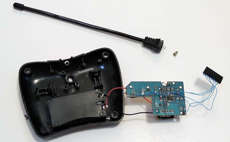
Figure 7. Hacking the controller. I made an interface cable connector from a female SIP header, but you could just straight-wire directly from the controller switches to the Amigo.
If you look closely, you’ll see only five wires from my makeshift connector: one for each switch and one for the common. I connected one side of each relay pair together at the header and wired those to the controller switch common.
You’ll also see the antenna disconnected, which I had to do to access the trace side of the circuit board. If you do have to remove your antenna, I suggest removing the controller battery (or batteries) first, and keep them removed while the antenna is not connected just to make sure the final stage of the transmitter is protected from an inadvertent reflected power zap.
Figure 8 shows my completed hardware setup, with the relay shield installed on my Amigo and connected to the controller via the ribbon cable.
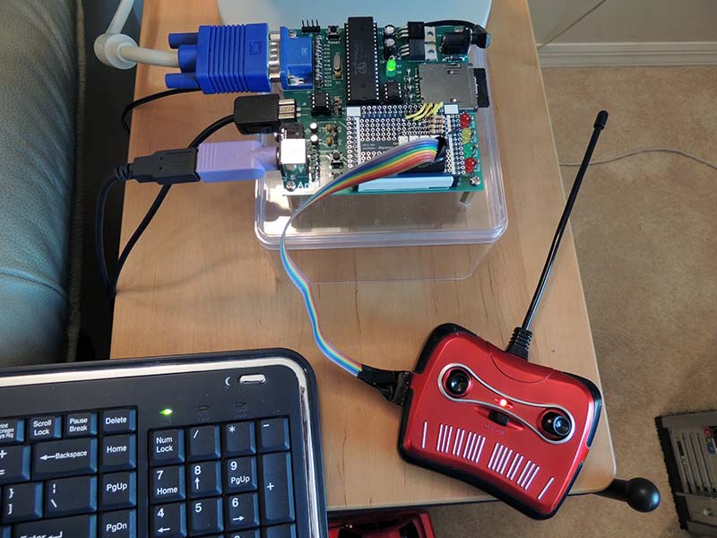
Figure 8. My completed setup, with the relay shield board in place and interfaced to the controller via a spiffy ribbon cable. It works! Now for the software ...
The first thing I did at this point was run RELAY.BAS to validate the functionality of all four channels with the controller and RC car.
For some reason, my system did not work on the first try, even though all interim tests had been successful. After I removed and reinstalled the car and controller batteries and spun the motors a couple of times, everything mysteriously began working as it should. With my Amigo now happily interfaced to the RC car, it was time for some software.
The first software design choice was whether to use the keyboard or the Wii™ classic controller for user input to control the car. I liked the feel of the Wii controller, but since some readers may not have that device, I decided to go with the keyboard and use the numeric keypad to “drive” the toy car around.
The scheme that I planned was to use the number “5” as the center “home” position, and the keys around the 5 key as directions relative to that center point. Thus, the 8 key would represent forward; the 2 key would be reverse; the 9 key would be forward right; the 1 key would be reverse left; and so forth. These INKEY values would turn on the appropriate relays, and an INKEY value of zero (no key pressed) would turn all relays off.
When I wrote a code snippet to validate this keyboard approach, my RC car stuttered forward, instead of moving smoothly while I held down the “8” key. Initial investigation showed that the INKEY command was returning some zeroes even when the 8 key was held down, which surprised me. Further investigation pointed to some timing issues between my Color BASIC code, the Spin keyboard interface code, and my keyboard. I found that I could manage this by inserting a PAUSE command in my BASIC code, but this made the car drive sluggishly.
The bottom line of all this was that I couldn’t use a zero value from INKEY (no key pressed) to stop the car (all relays off). So, I decided to use the 5 key instead, and accepted the approach of having to press a key to stop the car; 5 would turn all relays off.
This approach worked, and I quickly got used to pressing the 5 key to stop the zippy little car. In addition, I added a <spacebar> “all-stop” key just in case my old fingers (and old brain) got confused. I confess to using it more than once when “Zippy” was screaming headlong into the credenza. I also added some code that executes preprogrammed driving instructions.
(What good is computer control if you don’t actually do something with it?)
Here’s how my “car driving” code turned out, followed by a brief explanation of the key sections. There’s nothing illustrational in this code, and probably not much value to actually keyboarding it in. I suggest you download RACER.BAS from the downloads and copy it to your SD card. Then, you can tweak it as needed for your situation:
5 REM ***** AMIGO RACER *****
10 REM —- Initialize Things —-
15 F=12: B=13 REM <— Forward and Reverse I/O Pins
20 L=14: R=15 REM <— Left and Right I/O Pins
25 p=100 REM <— Pause in Milliseconds
30 j=0 <— Previous Keystroke
50 REM —- Print Main Screen —-
52 COLOR 63,22
54 CLS
56 LOCATE 15,1: PRINT “>>> AMIGO RACER! <<<”
58 LOCATE 4,3: PRINT “ > Use Keys 1-9 to Manually Control Car”
60 LOCATE 4,5: PRINT “ Or Function Keys For Stored Programs.”
62 LOCATE 3,7: PRINT “~~~~~~~~~~~~~~~~~~~~~~~~~~~~~~~~~~~~~~~~~~~~”
64 LOCATE 3,9: PRINT “7=FORWARD/LEFT 8=FORWARD 9=FORWARD/RIGHT”
66 LOCATE 3,11: PRINT “4=STOP/LEFT 5=STOP 6=STOP/RIGHT”
68 LOCATE 3,13: PRINT “1=REVERSE/LEFT 2=REVERSE 3=REVERSE/RIGHT”
70 LOCATE 13,15: PRINT “<SPACEBAR> = ALL STOP!”
72 LOCATE 3,17: PRINT “~~~~~~~~~~~~~~~~~~~~~~~~~~~~~~~~~~~~~~~~~~~~”
74 LOCATE 4,19: PRINT “F1=Hello F2=Circle F3=Waggle”
76 LOCATE 4,21: PRINT “F4=Your F5=Code F6=QUIT”
78 LOCATE 3,23: PRINT “~~~~~~~~~~~~~~~~~~~~~~~~~~~~~~~~~~~~~~~~~~~~”
100 REM —- Main Loop —-
105 k=INKEY
110 IF k=0 THEN GOTO 105
115 IF k=j THEN GOTO 105
120 IF k=32 THEN GOSUB 1000
125 IF k>207 AND k<214 THEN GOSUB (k-204)*1000
130 IF k<”1” OR k>”9” THEN GOTO 105
135 GOSUB 2000
140 GOTO 105
995 REM —- SUBROUTINES —-
1000 REM —- All Stop —-
1005 OUTA [F]=0: OUTA [B]=0: OUTA [L]=0: OUTA [R]=0
1095 RETURN
2000 REM —- Set Relays —-
2005 GOTO k+1961
2010 OUTA [F]=0: OUTA [B]=1: OUTA [R]=0: OUTA [L]=1: GOTO 2020
2011 OUTA [F]=0: OUTA [B]=1: OUTA [L]=0: OUTA [R]=0: GOTO 2020
2012 OUTA [F]=0: OUTA [B]=1: OUTA [L]=0: OUTA [R]=1: GOTO 2020
2013 OUTA [F]=0: OUTA [B]=0: OUTA [R]=0: OUTA [L]=1: GOTO 2020
2014 OUTA [F]=0: OUTA [B]=0: OUTA [L]=0: OUTA [R]=0: GOTO 2020
2015 OUTA [F]=0: OUTA [B]=0: OUTA [L]=0: OUTA [R]=1: GOTO 2020
2016 OUTA [B]=0: OUTA [F]=1: OUTA [R]=0: OUTA [L]=1: GOTO 2020
2017 OUTA [B]=0: OUTA [F]=1: OUTA [L]=0: OUTA [R]=0: GOTO 2020
2018 OUTA [B]=0: OUTA [F]=1: OUTA [L]=0: OUTA [R]=1: GOTO 2020
2020 j=k
2095 RETURN
3000 REM —- Run Program Step —-
3005 GOSUB 2000
3010 FOR n=0 TO t
3015 PAUSE p
3020 NEXT n
3095 RETURN
4000 REM —- F1 Program —-
4005 k=”8”: t=10: GOSUB 3000
4010 k=”5”: t=1: GOSUB 3000
4095 RETURN
5000 REM —- F2 Program —-
5005 k=”7”: t=5: GOSUB 3000
5010 k=”9”: t=20: GOSUB 3000
5015 k=”5”: t=”1”: GOSUB 3000
5095 RETURN
6000 REM —- F3 Program —-
6005 k=”7”: t=5: GOSUB 3000
6010 k=”9”: t=5: GOSUB 3000
6015 k=”7”: t=5: GOSUB 3000
6020 k=”9”: t=5: GOSUB 3000
6025 k=”5”: t=1: GOSUB 3000
6095 RETURN
7000 REM —- F4 Program —-
7005 REM <— Your Code Here
7095 RETURN
8000 REM —- F5 Program —-
8005 REM <— Your Code Here
8095 RETURN
9000 REM —- F6=Quit —-
9005 PRINT “bye!”
9010 END
9095 RETURN
Lines 5-78 of the program initialize a few variables up front (so you can conveniently change them if needed) and display the program main screen (see Figure 9).
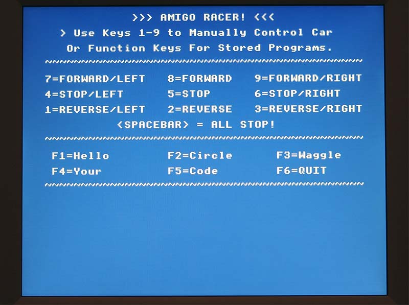
Figure 9. The Amigo racer software main (and only) screen. The program allows driving the RC car from the numeric keypad or from stored programs.
Lines 100-140 are the program main loop, which gets a keystroke and then takes action based on the key value:
- A key value of zero means no key pressed; get another keystroke.
- A value equal to the previous keystroke means no change; get another keystroke.
- A value of 32 (the <Spacebar> key) means “Emergency Stop;” turn all relays off.
- Values between 208 and 213 (inclusive) are function keys F1 to F6 and execute stored programs, including F6 Quit Program.
- Values between 49 and 57 are number keys “1” through “9” and set the appropriate relays.
- All other values are not assigned; get another keystroke.
The rest of the program contains the subroutines that execute the actions required by each “valid” keystroke. Lines 1000-1095 are the “emergency stop” subroutine, which uses the OUTA [x]=0 command to open all relays. Lines 2000-2095 set the appropriate relays for each numeric keystroke using a CASE statement built from Color BASIC GOTOs.
This may seem like a lot of code, but it runs faster than a nest of IF statements. Note that the order of the OUTA statements in this section avoids having “opposite” relays (Forward/Back or Left/Right) turned on at the same time.
Lines 3000-3095 run a single step of a coded “driving instruction” program by using the numeric value in variable k to set the appropriate relays, then running t times through a timing loop that includes the pause variable p.
You should adjust the value of the pause variable p to suit your car and driving conditions. My car runs much faster on tile than carpet.
Lines 4000-4095 represent one set of driving instructions; in this case, to drive straight ahead (k = “8”) for about one second (t x p = 10 x 100 milliseconds). Note Line 4010, which sends an “all relays off” command that should be used at the end of each set of driving instructions. The remainder of the program includes a couple of other simple driving programs, room for your own, and an explicit “Quit Program” option.
Even if you’ve had only limited exposure to BASIC, RACER.BAS should be fairly understandable to you. It’s simple, straightforward, and no frills. I think the Amigo is a great platform to introduce youngsters to programming fundamentals and simple hardware interfaces — all in one self-contained package that they can truly master.
With that mastery, comes confidence and the curiosity to try something else. Who knows where that might lead?
This completes our introduction to the Mentor’s Friend, and how you can use it to drive a toy RC car using a simple hack of the controller. The relay shield described in this article could also be used to hack many other switch-based controllers, so let your imagination run wild!
It gives your Amigo the ability to control loads of up to 500 ma with minimal muss and fuss, and there’s room on the shield board for some expansion. I hope you and a young protégé will give the Mentor’s Friend a try, and that it brings you many smiles! Have fun! SV
A kit is available from the SERVO/Nuts & Volts webstore that contains all the components to build the Amigo, including the pre-programmed EEPROM containing the Color BASIC “operating system” and a 2 GB SD card with the editor and some starter programs. Kit assembly is straightforward, with mostly through-hole construction, and the fact that you’re reading this magazine means that you probably have the tools and skills needed to make short work of the Amigo build.
Or, if you already have a Propeller board with PS/2, VGA, and SD card interfaces, you can “roll your own” Amigo by downloading the Color BASIC source, adjusting the I/O pin assignments to fit your board, and then compiling/uploading the resulting binary to the EEPROM on your board.
You can find the Amigo source code, schematics, and a description of Color BASIC here.
Or, if you are truly ambitious, download the Amigo schematic and build out the circuits using your favorite construction techniques. Then, download the Color BASIC source or binary and Flash it to your EEPROM.
Article Comments