Get A Starter Motor Runnin’ In Your Robot
By Steven Schmitt View In Digital Edition
Auto starter motors are often overlooked for use in robot building. Typically, a starter motor can draw 50 to 150 amps with no load and over 1,000 amps under heavy load so they may appear to be difficult to use. Since nearly all are series wound (SW), they can be as good as or better than permanent magnet (PM) motors for powering combat robots. Plus, they are inexpensive and readily available.
The torque of an SW motor is proportional to the current squared whereas the torque of a PM motor is only proportional to the current. The torque and horsepower curves for the two different types of motors are shown in Figure 1.
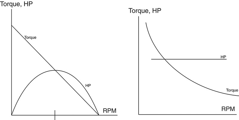
FIGURE 1.
The torque vs. RPM curve for the PM motor is very linear and the peak horsepower occurs at the midpoint. The torque vs. RPM curve for the SW motor is very non-linear making the horsepower curve nearly flat over a large RPM range. While the PM motor lacks power at both low and high RPM, the SW motor creates high torque at low RPM and has a nearly unlimited high end. PM motors are very compact and have high efficiencies, but only over a small RPM range. For applications where operation is needed over a large RPM range, the SW motor is both more efficient and compact (as long as you have unlimited current for free! -Ed.).
A good example of where SW motors dominate is the National Electric Drag Racing Association (NEDRA). Most — if not all — electric powered drag race cars use SW motors. Maniac Mazda does wheelies and over 100 mph in a quarter mile drag race.
Starter motors require a battery pack with a rating on the order of 500 cold cranking amps or (to be more accurate) the ability to source 500 amps at 10 volts. The Panasonic 1220 SLA battery can power a small starter motor for two or three minutes.
The compact starter motors used in autos cannot be over volted in any way. Basically, they are designed for very short duty and after a few minutes of use, get very hot. Running them for five minute matches is the extreme limit.
The power output of starters range from 1 to 2 kW. It is normal to find similar starters used on different brands of autos. Photo 1 shows a few typical starter motors.
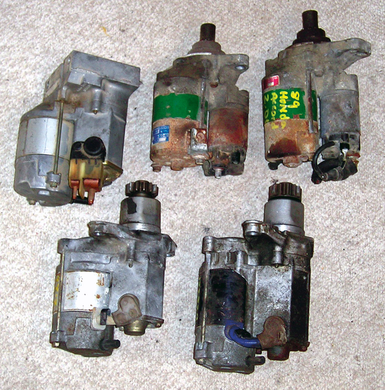
PHOTO 1.
The two motors in the upper right side are from late 1980’s Hondas. The larger motor was used in cars like the Accord, while the smaller one came from a Civic. The large motor on the bottom is a Denso starter used on many Toyota models. The two starters on the left are newer style Denso starters from a Toyota and a Corvette.
Auto salvage yards can be a good source for used starters. They typically have a core pile waiting to be sold to a buyer for remanufacturing and are usually worth only a few dollars. In my experience, few starters ever wear out. Most often the solenoid goes bad and the relay inside it quits working. For robot use, starter cores are the best value.
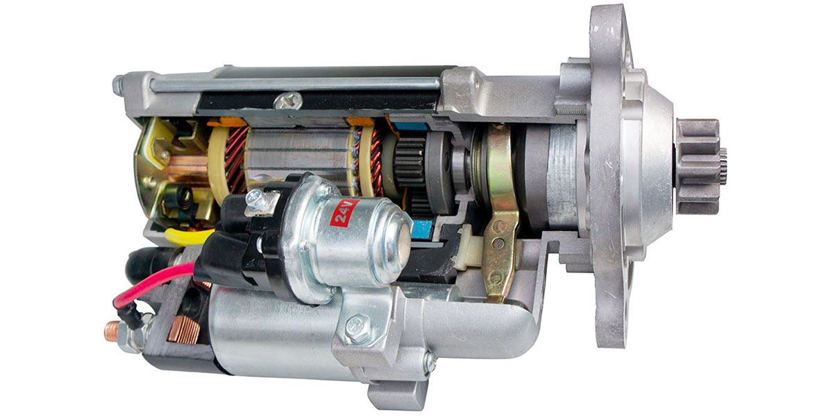
All starters have the same basic parts: a motor, gear reduction, starter solenoid, and something that is generally called a Bendix. Most of these parts have to be modified or discarded before the starter can be used in a robot.
One necessary modification is to make the SW motor reversible. It cannot be reversed by changing the polarity of the input voltage. Instead, the polarity of the field winding has to be inverted relative to the armature winding. This modification will be covered later.
Since the Bendix is an over-running clutch that only drives in one direction, it has to be modified to drive in both directions. The final challenge is to attach a drive sprocket of some sort to the starter. For some uses, it may be easier to use the gear that came with the starter and find a flywheel to match it. There are only a few standard gear pitches used for most autos making it easier to find a flywheel or ring gear to match the starter. These modifications will also be addressed later.
A starter motor can be modified in a few hours with great results. Driving a robot with PM motors is okay but a robot with SW motors is a totally different experience. The robot will have an awesome hole shot and will feel like it can accelerate forever.
I use a simple relay control system and have never investigated using an electronic speed controller (ESC) to control a starter motor. One problem with using an ESC is that only the field winding is controlled by the H-bridge. The simplest solution would be to use relays for the H-bridge and use the ESC to control the current to the motor. The relay control circuit is shown in Figure 2 with a possible PWM modification.
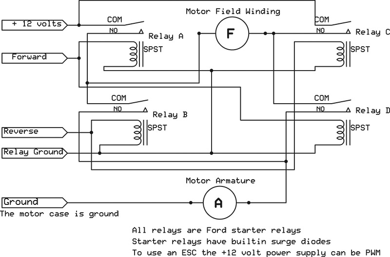
FIGURE 2.
Rewiring the Motor to Make it Reversible
Since most starters are similar, these modifications will apply to almost all of them. Photo 2 shows the disassembled Honda starter motor and Photo 3 shows the parts that have to be modified. Starters are four-pole motors equivalent to having two motors in parallel. There are two sets of field windings and two sets of brushes.
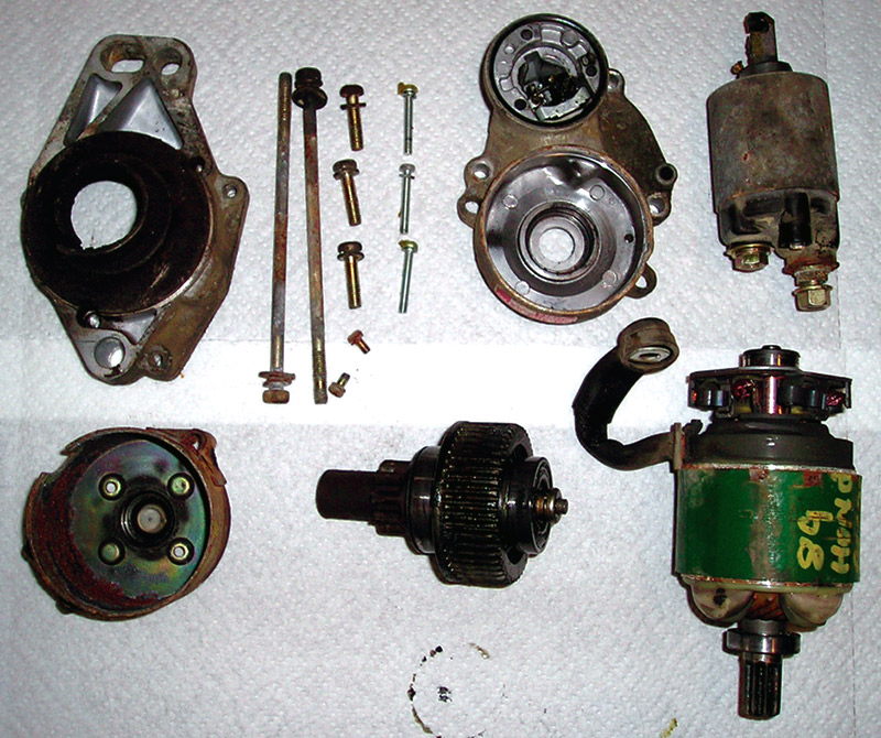
PHOTO 2.
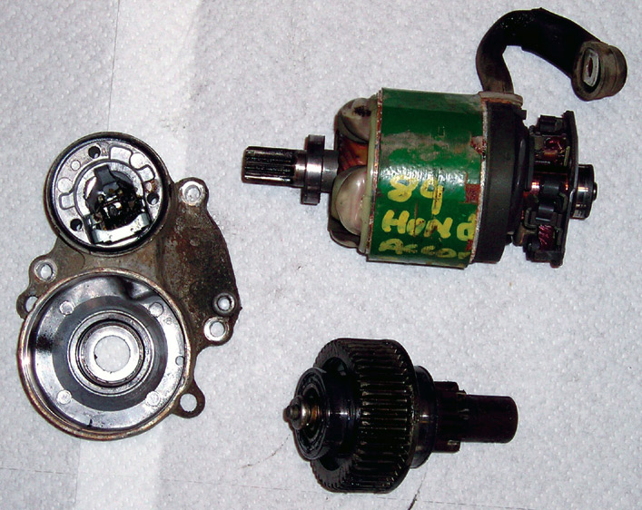
PHOTO 3.
The power input goes to the two sets of field windings. The fields are connected to two brushes which power the armature. Finally, there are two more brushes connected to ground to complete the circuit. Photos 4 and 5 show the field and armature and how the two brushes are welded to the field. Note the complete lack of wear on this 1989 starter motor that was removed from a junk car.

PHOTO 4.
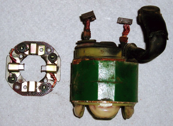
PHOTO 5.
The modification requires that the field be isolated from the armature so its polarity can be reversed. Photos 6 and 7 show a close-up of the spot welds connecting the field to the brushes and how the welds can be pulled apart. The welds are made by wrapping the stranded wires with copper foil and applying heat and pressure to finish it. The welds are not very strong and the foil can be unwrapped as shown.
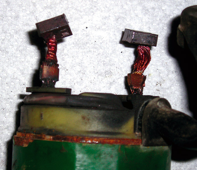
PHOTO 6.
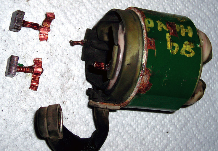
PHOTO 7.
The next step is to attach wires to the field so that both ends of the field windings are outside the case. Since there is very little room in the case, the connections have to be very compact and neat. Also, solder connections will not hold up to the heat and vibration of the motor. Therefore, only a spot weld or crimp connection will work. For the crimp connection, brass rings made for 3/16” compression fittings can be purchased at any plumbing store.
While in use, the motor will get very hot and any plastic tape or plastic wire insulation will fail. High temperature automotive wire with rubber insulation and cloth electrical tape are needed to make the modification. Since the tape has little adhesion, it needs to be secured. Cotton thread works well.
Photo 8 shows the wires spliced to the field and routed out of the case. At the top center is the finished connection while the bottom center shows an exposed connection. The 3/16” compression sleeve accommodates the field wire and 8 gauge wire.
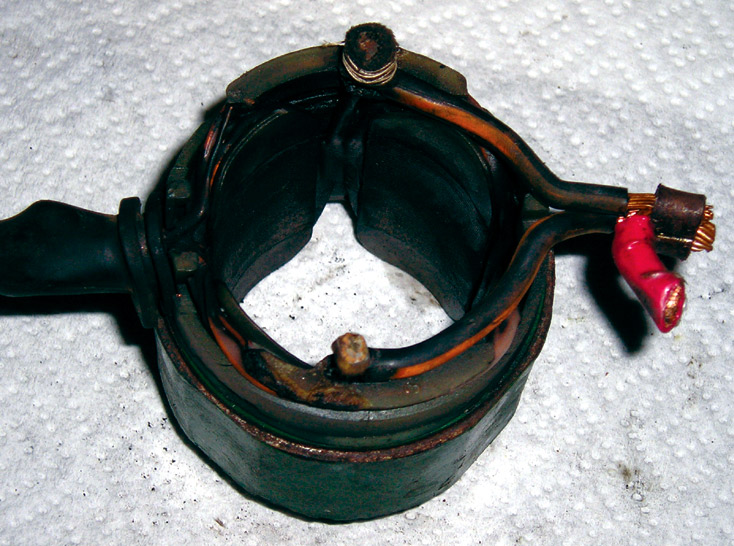
PHOTO 8.
The next step is to splice wires to the brushes so they can be connected to the H-bridge. Photos 9 and 10 are 8 gauge wires spot-welded to the brushes and the brush holder with all four brushes. The connections to the brushes can be either spot welds or crimps with the 3/16” compression sleeves. In Photo 9, the red wire had plastic insulation which melted during welding, while the black wire was rubber insulated. Once again, the wires are insulated with cloth electrical tape and held in place with thread.
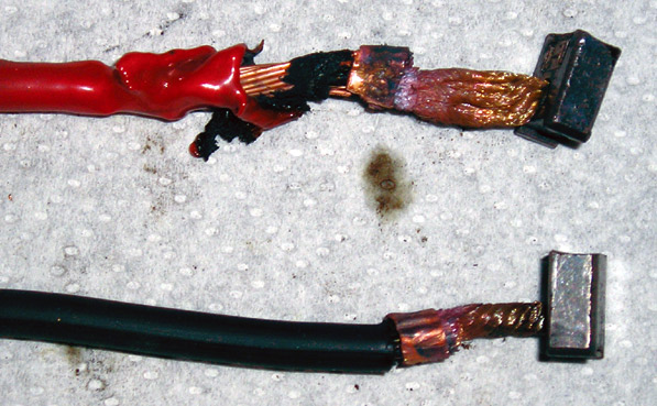
PHOTO 9.
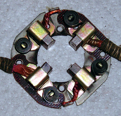
PHOTO 10.
Photo 11 demonstrates how the field and brush holder go together and the challenge of fitting it into the tiny space.
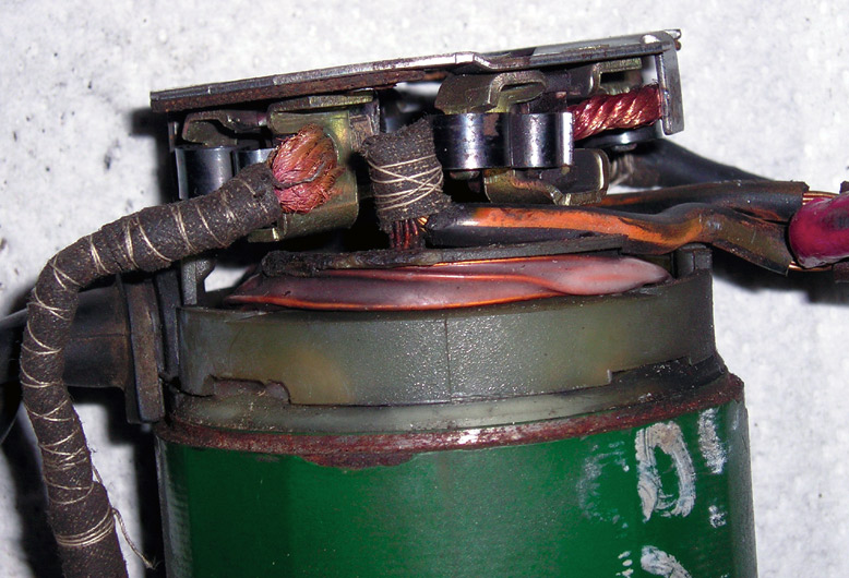
PHOTO 11.
The end cap for the motor is modified with several deep slots so the new wires can be routed out of the case in the least amount of space as shown in Photo 12.
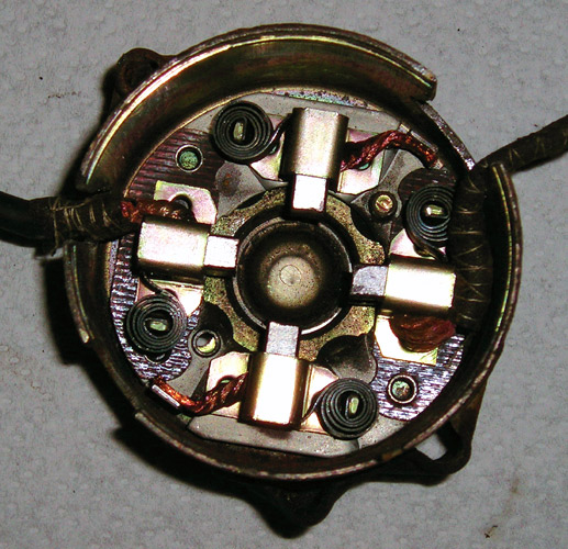
PHOTO 12.
After these electrical modifications are completed, the one-way clutch from the Bendix needs to be disabled. Photo 13 is the Bendix unit and Photo 14 is the Bendix unit disassembled. The one-way clutch has five rollers that lock in one direction and release in the other direction. The modification is to replace the five rollers with five much larger rollers and then grind five slots in the inner shaft to accept the larger rollers.
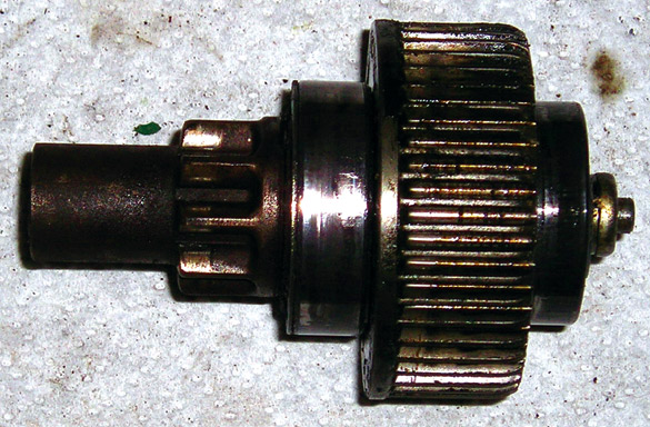
PHOTO 13.
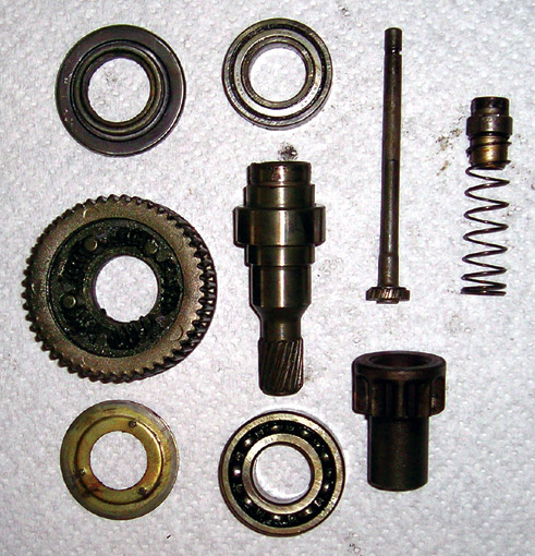
PHOTO 14.
Photos 15, 16, and 17 show the ring gear with three of the five small rollers; the ring gear and shaft with five slots ground into it; and the ring gear with the five large rollers and inner shaft all assembled. (The third photo was taken from the top so the shaft is not very clear.)
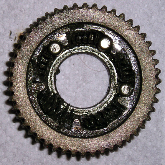
PHOTO 15.
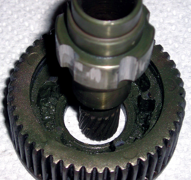
PHOTO 16.
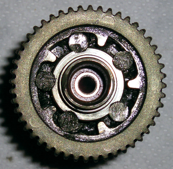
PHOTO 17.
The completed motor in Photo 18 has two leads from the field windings and one lead from the armature. The case ground is the other connection to the armature. A few unneeded parts have been sawed off the case to make the motor more compact.
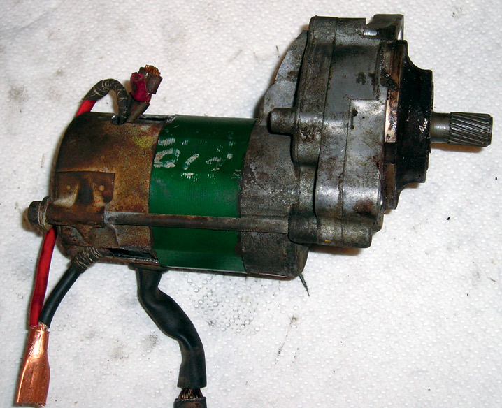
PHOTO 18.
To attach a sprocket to this motor, set screws can be used successfully, however, special care is needed. Four flat spots are ground onto the shaft to accommodate four set screws that are equally placed around the sprocket. To prevent even microscopic movement, everything needs to be epoxied together. This includes the sprocket to the shaft and the set screws to the sprocket. A hose clamp epoxied around the whole assembly provides further support to keep the set screws from loosening. The sprocket collar should be thick enough to allow six or more threads for the set screws. Any less and the set screws will shift around and work loose.
Wrap-Up
A few hours of work will turn a junk starter motor into a powerful and compact drive motor for a combat robot. Series wound starter motors with modifications to make them reversible and drive in both directions provide excellent low end torque and high speed. SV
Article Comments