
Get Rolling with Omni-Directional Wheels
By Moein Jafari View In Digital Edition
There are several types of differential drive wheels for use in mobile robots, and each has its limitations and costs. Omni-directional wheels are becoming popular among robotic teams because they address one of the major limitations of traditional wheels; namely, the need to rotate first to move from one point to another in a straight path. In this article, we’ll look at some omni-wheeled robots and applications.
Introduction
There are several ways to enable robots to move on a solid surface, such as using wheels and legs. Because wheels provide speed and ease of control, they are typically the first choice for robots in the middle size, small size, and junior robot soccer leagues.
The omni-directional wheel is a kind of wheel that can freely roll in more than one direction. It’s popular for mobile robots since it doesn’t need to rotate first for moving from one point to another in a straight path. Moreover, moving along a path can be combined with rotation, so the robot can arrive to its goal at the correct angle. The omni-directional wheel was patented in 1919 by J. Grabowiecki in the US. Figure 1 shows a figure from that patent.
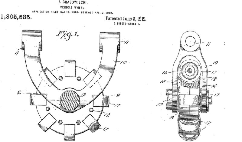
FIGURE 1. Drawing of one of the first omni-directional wheels, as described in Grabowiecki’s 1919 US Patent.
Omni-wheels have smaller rollers on the edges that move completely perpendicular to the wheel itself. With this type of wheel, they must be mounted perpendicular to the center of the robot. A popular type of omni-wheel is the Mecanum, which is unique in that the small rollers are at a 45 degree angle. This allows them to be mounted like normal wheels but provide the same style of movement as omni-wheels.
In use, a total force vector in any desired direction is produced and can move the platform in any direction without changing the wheel’s direction. Refer to Figure 2.
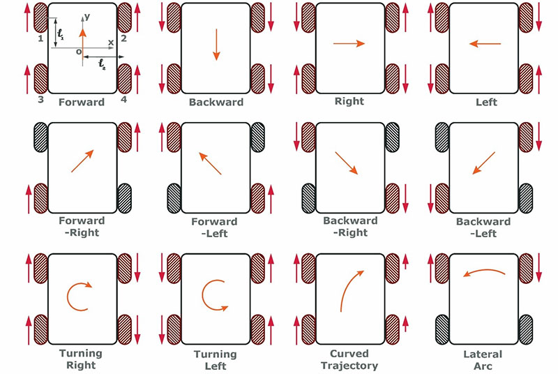
FIGURE 2. Mecanum wheel mechanisms.
Omni-directional wheels can be thought of as normal wheels with the ability to roll or slip sideways. Think of them as powered casters. The general principle of an omni-directional wheel is that while the main wheel provides traction in the direction normal to the motor axis, it can slide frictionless in the motor axis direction because of the small rollers.
The Role of Rollers
The number of rollers can affect the performance of omni-directional wheels. The dead area between the wheels causes friction and vibration. This dead area can be reduced by mounting the rollers closer together or by using double-plated wheels made with two plates of passive rollers. Double-plated wheels don’t have the dead area in between the rollers. When they roll, the double plates take turns bearing the load. This results in smooth movements in comparison with single-plate omni-directional wheels.
The moving mechanisms of an omni-directional wheel are shown in Figure 3.
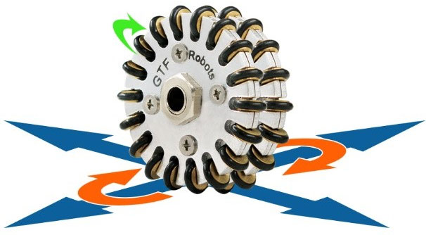
FIGURE 3. The moving mechanisms of an omni-directional wheel.
Omni-Directional Wheel Arrangements
The most common wheel arrangements for a robot are three or four wheels. A two-wheeled arrangement is possible, but problematic. For example, if it were possible to place both omni-directional wheels orthogonally oriented exactly under the center of a circular base robot, one could drive the robot in any desired direction without rotation. Consider the Cartesian coordinate system attached to the robot and the robot speed in this system. In this arrangement, each wheel provides one of the two speed components.
However, this is not practical because of the space requirements for the motors and wheels, and the likely instability of the robot. A solution is to include some caster wheels and a different drive technique, such as in Figure 4.
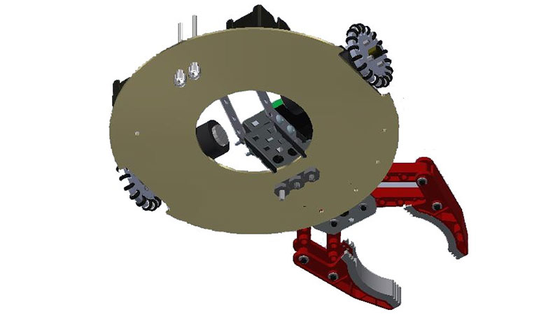
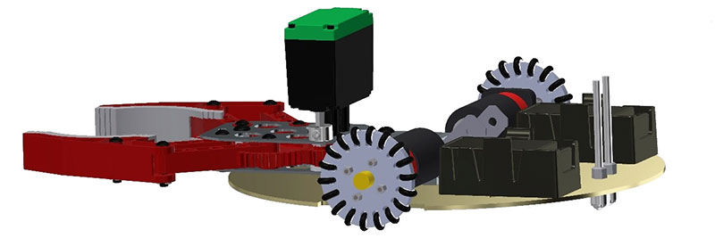
FIGURE 4A and 4B. Robot featuring two omni-wheels.
Because of rotational torque, driving on a straight path would be difficult.
A better solution is to use a three-wheeled robot, such as shown in Figures 5 and 6.
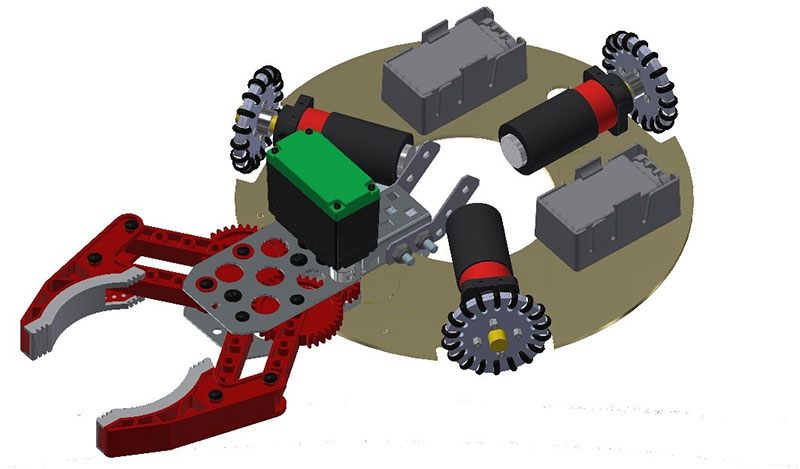
FIGURE 5. A three omni-wheeled robot with a 120 degree angle between them.
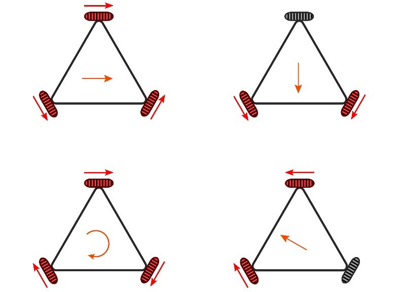
FIGURE 6. Moving mechanisms of a three-wheeled bot.
In a four-wheeled configuration (refer to Figure 7), simple control is sacrificed for higher traction.
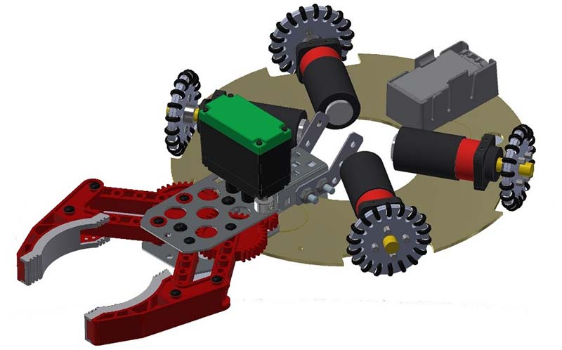
FIGURE 7. A four-wheeled version.
This arrangement has a more complex mechanism. A popular configuration is locating the wheels around the periphery of the robot. Because of this arrangement, wheels can rotate the robot’s frame in addition to moving the robot forward. A DC motor for each wheel can be used and each motor can be controlled by a PID controller.
The mechanisms of moving a robot using four omni-directional wheels is shown in Figure 8.
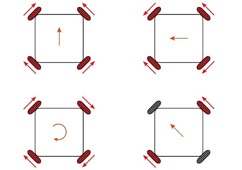
FIGURE 8. Moving mechanisms of a four-wheeled bot.
Conclusion
Omni-directional wheels are popular in mobile robots. Why not try implementing them in your next build? While there are a few disadvantages, the flexibility of movement makes them worthwhile. SV
References
F. Ribeiro, I. Moutinho, P. Silva, C. Fraga, N. Pereira. Three Omni-Directional Wheels Control on a Mobile Robot, https://www.scribd.com/document/421813982/10-1-1-99-1083-pdf.
R. Rojas, A. Förster. Holonomic control of a robot with an omni-directional drive, KI-Künstliche Intelligenz; www.mindraces.org/review_documents/20062007/deliverablesM36/deliverablesD63/RojasFosterEtAl2006.pdf.
Y. Liu, J.J. Zhu, R.L. Williams, J. Wu. Omni-directional mobile robot controller based on trajectory linearization, Robotics and Autonomous Systems 56 (2008) 461–479; see downloads.
S. Soni, T. Mistry, J. Hanath. Experimental Analysis of Mecanum wheel and Omni wheel, IJISET - International Journal of Innovative Science, Engineering & Technology, Vol. 1 Issue 3, May 2014; www.ijiset.com; see downloads.
Article Comments