
Experimenting with Walking Robots — A Humanoid Platform
By John Blankenship View In Digital Edition
This series of articles explores the trials and tribulations associated with my experimentation with walking robots. This installment examines one option for the hardware and sensor requirements for a robot with two legs.
Most hobbyist-oriented walking robots are programmed to move using a series of frame-based poses. The first article in this series demonstrated that walking could also be accomplished with the four-leg robot in Figure 1 using a series of simple movement routines (lift leg, leg forward, straighten leg, etc.).
Using such routines makes it possible to incorporate sensor data to control movements. For example, a lifted leg generally needs to be straightened in order to step forward. Rather than always straightening the leg to a fixed position (as is done with frame-based animation), it would be nice if the robot could stop the extension when a foot sensor indicated the foot had reached the ground.
The second article in the series programmed the robot in Figure 1 to monitor foot switches, as well as an accelerometer to determine the robot’s tilt. This information allowed the robot to keep its body level by altering the length of its individual legs. Eventually, I plan to utilize the sensor-based leveling techniques discussed in that article to improve the robot’s walking capabilities.
I learned so much from trying to balance a four-legged robot though, that I thought it could be beneficial to explore balancing a two-legged robot before continuing with my other experimentation.
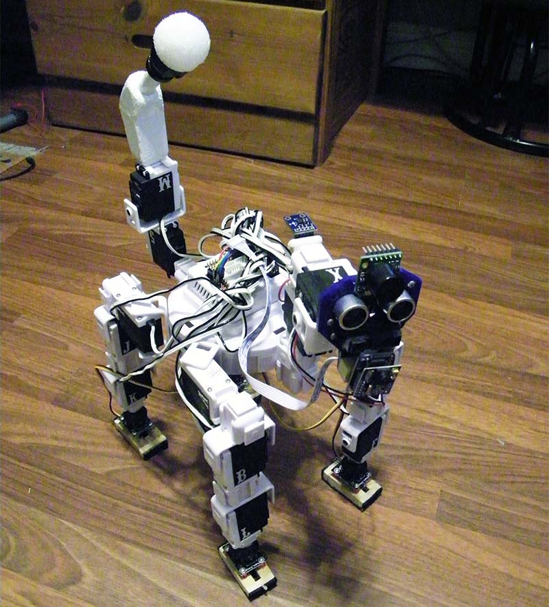
FIGURE 1.
A Humanoid Platform
If you want a two-legged walking robot, a quick Internet search will show everything from low-cost beginner bots to high-end sophisticated (and expensive) choices. I chose to use parts from EZrobot because they easily clip together to build their robots or most any robot you can imagine (such as my four-legged walker in Figure 1).
The whole point of this series of articles is to encourage experimentation though, so don’t think you need to agree with or utilize my choice. The programming algorithms discussed in these articles will be generic in nature and should be applicable to almost any walking platform you might use.
EZrobot’s humanoid robot is called JD and is shown in Figure 2. His hands are cute, but are not really all that useful when it comes to practical activities. Since my current goals focus only on walking, I decided to replace the arms with something more appropriate for my experimentation. Again, because I was focusing on walking, I also wanted to improve the legs.

FIGURE 2.
JD’s feet are really nice in that they each have two servos allowing the ankle to lean left and right as well as forward and backward. The problem is each leg has only three servos (including the two in the foot), so he needs at least one more joint to provide a proper hip, knee, and ankle configuration. Without the extra servo, his walk will always be more of a shuffle.
Figure 3 shows my first attempt at building a two-legged walker from EZrobot parts. As you can see, I added two additional servos to each leg. The lower of the two servos provides a thigh, giving him proper hip and knee joints while maintaining the two-dimensional ankle.
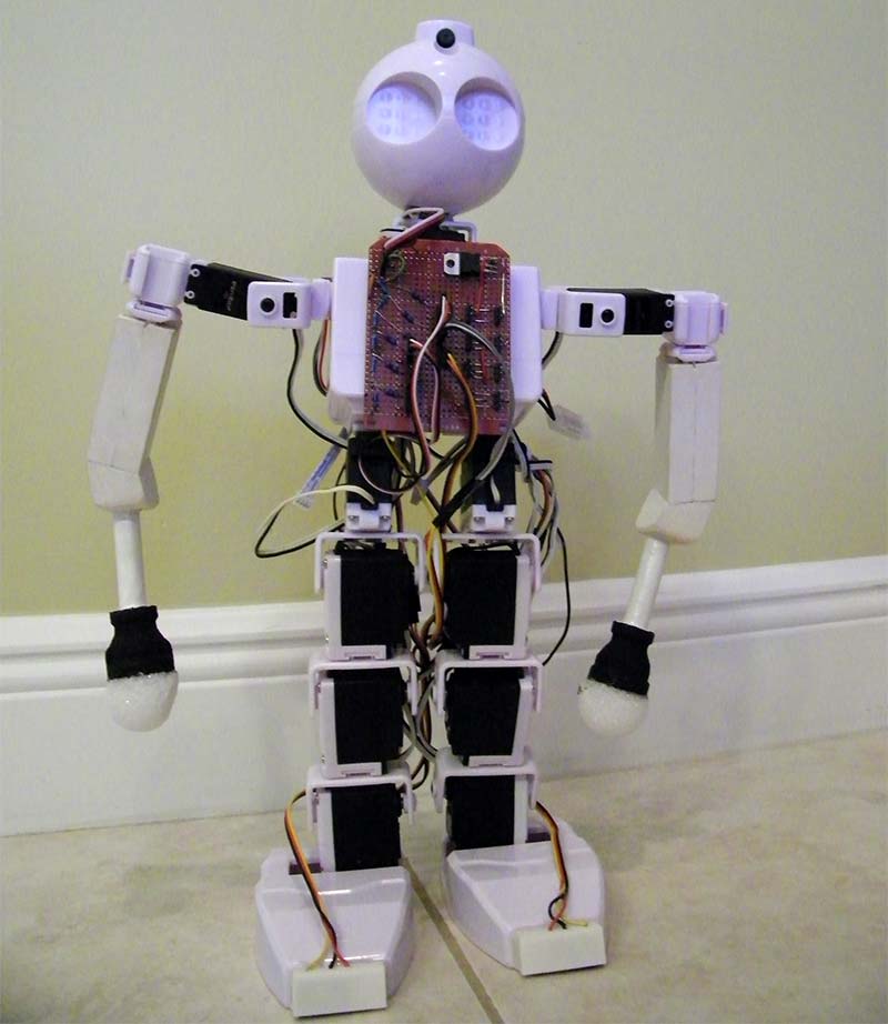
FIGURE 3.
The upper servo can swivel the leg, turning it either left or right. Ideally, this would make it easier for the robot to turn left and right, but unfortunately the added height produced issues.
With two new servos in each leg, the high center of gravity coupled with the combined slack in all the servo gear trains created significant instability, making it very difficult for the robot to balance. Furthermore, the increased height put so much torque on the ankle joints that it actually cracked one of the servo brackets during some of my tests.
After much experimentation, I finally decided to just remove the rotational hip joints. This produced the robot shown in Figure 4. It has two servos for the head, two for each arm, two for each leg, and two for each ankle (14 in total).
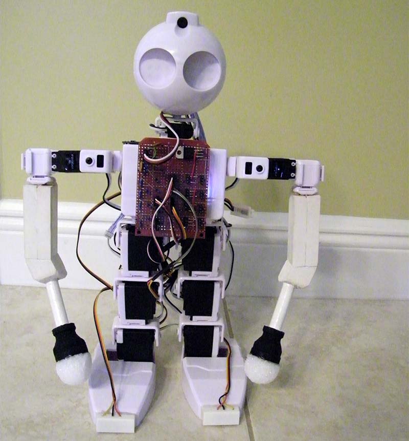
FIGURE 4.
I don’t think my final version in Figure 4 looks quite as good as Figure 3, but in my opinion, it is better proportioned than the original JD, and the extra leg joints certainly provide a better opportunity for creating a natural walking motion. Notice also, that I replaced JD’s arms with wooden ones tipped with iron pipe fittings and Styrofoam™ balls (much like the tail in the four-legged walker in the earlier articles).
Since the arms can move forward and backward as well as side to side, the extra weight at the end of each arm can be used to help the robot maintain his balance. If the original arms and hands are used (they do look nice), it adds four more servos for a total of 18.
Sensors
Notice the wires coming from the robot’s toes in Figure 4. These connect to snap action switches to provide feedback about the foot’s contact with the ground. Each foot also has two switches at the back of each heel.
Figures 5 and 6 show these switches looking at the bottom of the foot. The mounting of these switches was discussed in my article here.
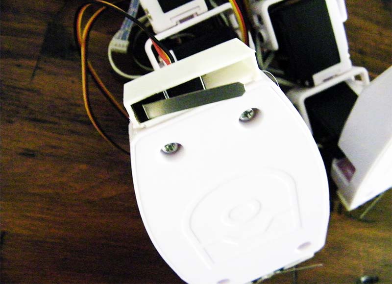
FIGURE 5.
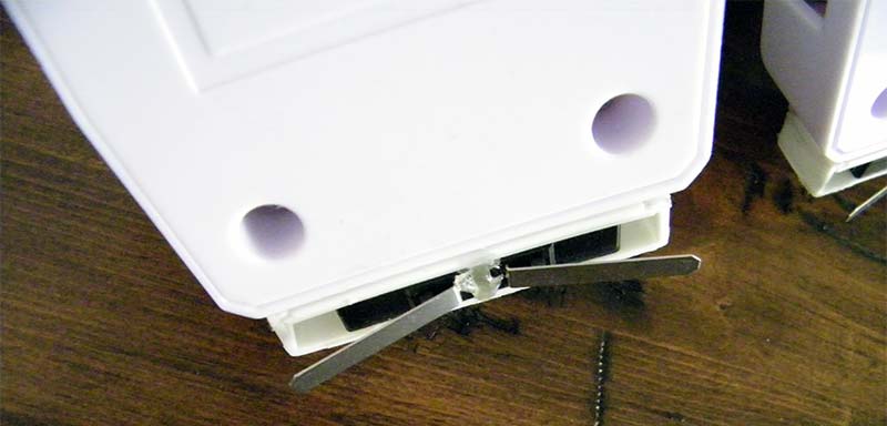
FIGURE 6.
When all the switches are activated, the robot’s foot should be flat on the ground. The remaining states of the switches provide information about how the foot is tilted with respect to ground (both left and right as well as forward and backward). This information can help the robot determine how to move its ankle motors to ensure the foot is making proper contact.
With six foot switches (three on each foot) plus the 14 servomotors needed for the robot in Figure 4, we will need at least 20 digital I/O lines to control the robot. If someone wants more switches (perhaps on the end of each arm) and/or wants to use JD’s original arms and hands, the number of needed I/O lines can climb to 26.
This can be a major problem because the EZrobot computer only has 24 digital I/O lines and eight analog ones. Even though this is more lines than you will find on many microcontrollers, this is certainly a limitation I want to avoid.
Digital Input Using an Analog Port
I chose to solve this problem by interfacing the foot switches using analog port pins. This is usually accomplished by simply connecting the digital signal directly to an analog input. The digital state can be considered a logical one if the analog level exceeds some threshold, and zero if it does not. Unfortunately, this method would utilize six of the analog lines (eight if you decided to add switches to the ends of each arm).
This was another deal breaker because I needed two analog inputs for an accelerometer to monitor the robot’s tilt (see Part 2 of this series). Furthermore, I want the option to eventually add IR and/or ultrasonic ranging sensors that interface through an analog port.
Obviously with these constraints, I needed to think out of the box to solve this problem.
The basic idea behind my solution was to interface the switches to a digital-to-analog converter (DAC). This simply means that various combinations of the switches would produce different amplitude levels of the analog voltage. On the surface, this presents a workable option, but we need to determine how many switch states can be accurately extracted from an encoded analog signal.
The analog ports on the EZ computer are 12 bits, allowing them to detect up to 4,096 different amplitudes. Remember though, the robot’s battery can easily be driving a dozen servomotors simultaneously which can cause a significant amount of power supply related noise.
This RF noise — coupled with that from imperfect switch contacts — induced in the cables, etc., can easily exceed a 2% level. Such levels could result in an 80 point fluctuation which could alter the values of the lower seven bits of an analog reading.
Furthermore, I was planning to build my digital-to-analog encoder using 5% resistors which would introduce even more potential inaccuracies.
I built several test circuits and determined I could encode up to four digital lines into a single analog signal and retrieve them with 100% accuracy. Since my two-legged walker required six switches, I created two three-bit DACs (one for each foot) as shown in Figure 7.
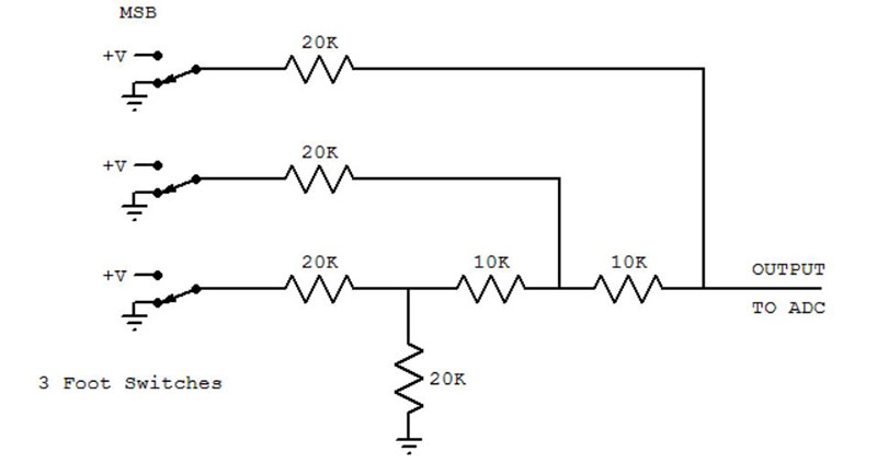
FIGURE 7.
The construction of these DACs can be seen in Figures 3 and 4 on the circuit board mounted on the robot’s chest.
Notice in the figure that the snap action switches simply apply the power supply voltage (3.3 volts for the EZ controller) or ground directly to the circuit. This is very important because this means the inputs to the converter are always fixed values.
If the inputs were outputs from a typical digital I/O line, the amplitude could vary considerably, significantly reducing the accuracy of this approach. This means that while this approach works for switches, it may not be as effective for typical digital signals.
In the figure, the inputs are grounded when the switches are not activated, but either approach is fine because the bit logic can easily be reversed in the software. Converting the analog signal to digital is easy. I simply added a slight offset to compensate for possible problems due to resistor tolerances and then divided by 512 (leaving only the top three bits in the original data).
The actual offset you need to use might vary based on the tolerance of the resistors utilized, but I built several circuits (both three- and four-bit) and the offset of 64 always worked.
In summary, if we assume we have a variable A that holds the analog reading and we want to convert it to a three-bit digital value stored in D, we can do so with this statement:
D = (A+64) / 256
What’s Next
Now that I have a humanoid platform complete with sensors and ready for experimentation, the next article in this series will explore ways for my two-legged robot to autonomously maintain its balance. SV
Article Comments