Designing a New Workbench for Your Robotics Hobby - Phase 2B
By James Lyman View In Digital Edition
We’ll take up where we left off in the previous issue, adding more accoutrements to our newly designed workbench. We’ll start with accommodating the long instruments that won’t fit on the instrument shelf.
The Oscilloscope and Other Long Instruments
In the first part, I mentioned the problem of long instruments fitting on the shelf since they’re about twice as long as the other devices. That meant the long instrument would extend past the other units by 7-10 inches. My solution was a cart sitting on the benchtop itself, that can easily be moved around the bench as needed. I have two “long” Textronix pulse generators that I frequently use, as well as my oscilloscope. The first step was to determine the dimensions for the caddy, which I did by stacking my instruments together (Figure 1) where the oscilloscope sits on top of the pulse generators.
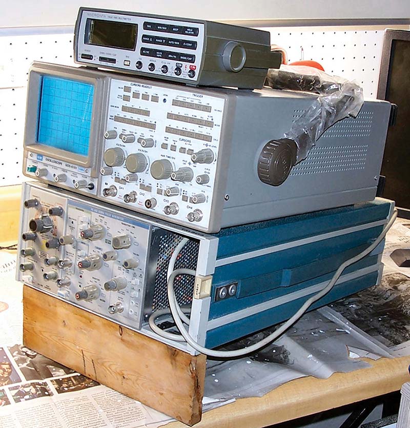
Figure 1. Stacking the oscilloscope and pulse generators to determine their angle of rest.
I slipped various sizes of boards under the front of the stack, so they sat at an angle to determine what angle was the most comfortable to work with. Once I determined and measured the angle, the next step was to build the table they would sit on.
I used 1x6 boards glued together side by side to form a single board but could have used 3/4 inch plywood instead. The table was easy to do; I just cut it to the required length and width. To make it easier to use, I mounted the table on a Lazy Susan (shown in Figure 2), which allows the instruments to easily rotate with just a nudge.
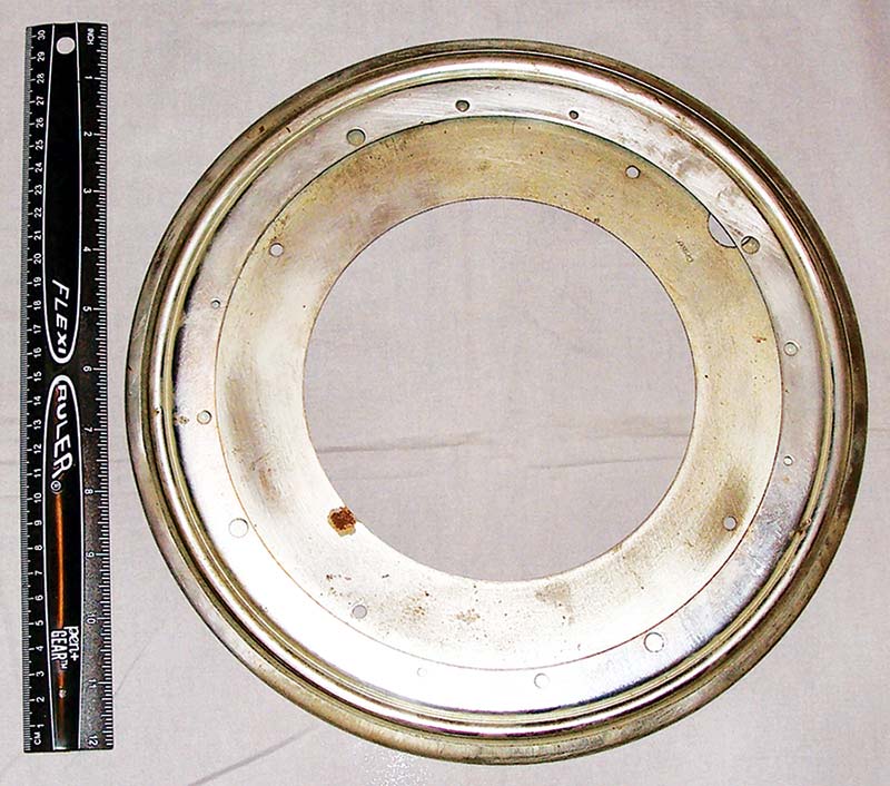
Figure 2. The Lazy Susan device used to allow the instrument cluster to easily rotate horizontally.
The Lazy Susan is two metal plates separated by a string of ball bearings that allows the plates to easily rotate. Both the upper and lower plates have holes for mounting with screws. I bought the Lazy Susan from one of the major building supply stores, although they can be found on the Internet. It mounts between the table and a wooden base, which sets on the benchtop. The base is made from the same glued-together wooden boards as the table but is a little larger than the Lazy Susan.
I could have cut the base as a circle but decided that an octagon base would do just fine. I started by drawing an outline of the Lazy Susan as a circle centered on the board. Using the circle as a guide, I drew a square with each side about 1/2 inch from the circle, then used a combination square set at 45 to draw the lines for the four corners so each side is equal as shown in Figure 3.
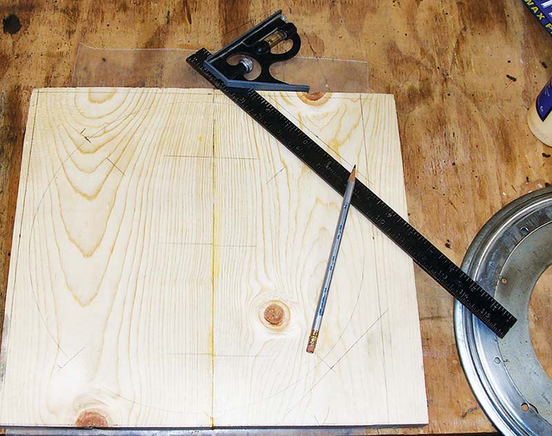
Figure 3. Laying out the caddy base for cutting.
Once the lines are drawn, just carefully cut straight along them. Finally, the two angled handle holders are made from the same 3/4 inch wood, each with a slope the same as the angle measured at the start. The handle (which these two parts hold) is used to move and rotate the instruments on the bench and is attached by passing a round wooden stick through the holes. Looking at Figure 4, you can see the handle holes (lower left corner) and the slope for the instruments.
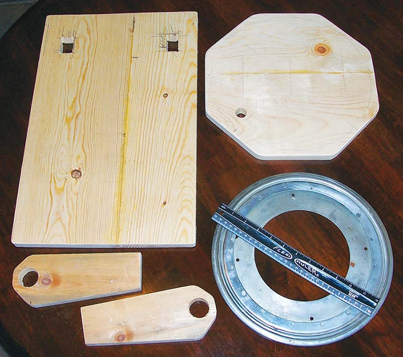
Figure 4. The parts for constructing the oscilloscope caddy.
Also note the two square holes on the table (upper left corner). The pulse generator has feet; there’s one on each corner, about 3/4 inch high. Wanting to keep the stack as low as possible, the two square holes were cut out for the rear feet to drop into.
Figure 4 shows the basic components for the caddy, which can now be assembled. The first is the mounting of the handle holders using wood glue and screws. Using the pulse generator instrument, I positioned the holders so the instrument rests along the full top edge of each holder, then marked the positions using a pencil. Once the holders are glued in place, they’re secured using wood screws from the bottom of the table as seen in Figure 5.
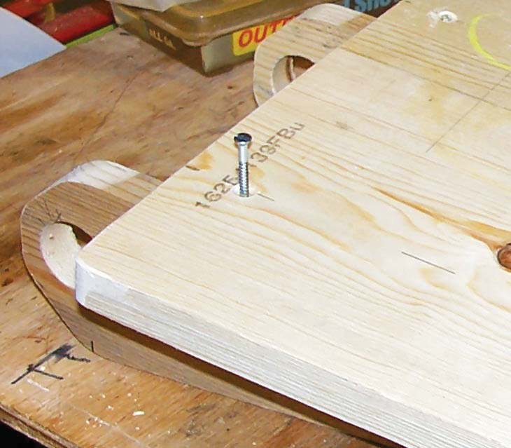
Figure 5. Installing the handle holders on the table from its bottom with wood screws.
The screws must be countersunk to avoid interference with the Lazy Susan.
A 1-1/4 inch wooden dowel used for clothes hanger rods passes through the holes in the two handle holders as seen in Figure 6.
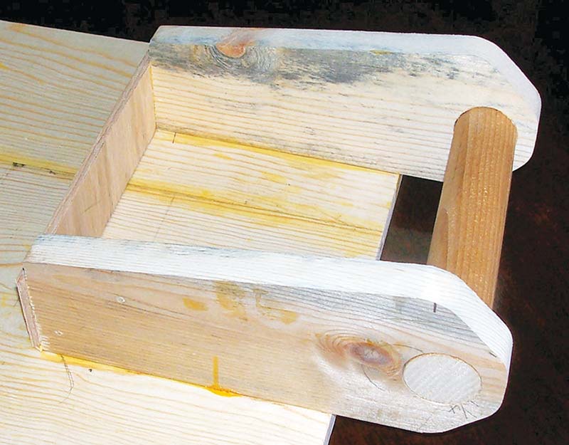
Figure 6. A 1-1/4 inch wooden dowel rod is inserted through the holes in the handle holders and is held in place with wood glue.
After the glue dries, it’s cut flush with both holders. Additionally, a plywood back is glued and nailed to the backs of the holders for use as a mounting plate for a power strip.
This also acts as a ‘close off’ to keep small objects from sliding under the instruments and becoming lost, since no doubt this front area will make a useful storage area for small items.
Next, the Lazy Susan is mounted to the base using four screws (Figure 7).
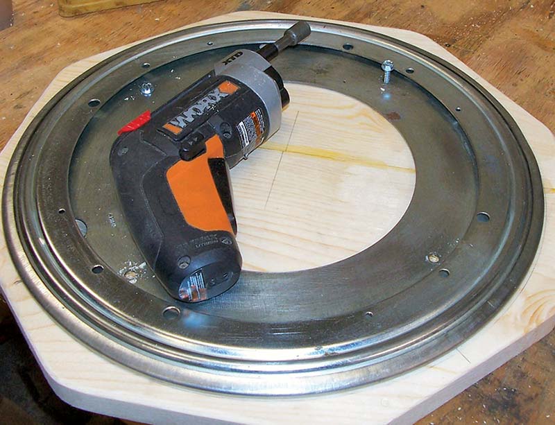
Figure 7. Mounting the Lazy Susan to the caddy base using four wood screws. Note the one screw part way installed through the inner rim (upper right side).
The Lazy Susan is carefully aligned with the pencil outline of it previously marked on the base. Notice the hole through the inner lower metal plate (between the 8 and 9 o’clock position of the Lazy Susan).
This must be marked with a pencil on the base, then a hole the same size drilled through the wooden base. This hole allows screws to be installed for mounting the Lazy Susan to the instrument table.
Figure 8 shows this method of using the hole to mount the base and Lazy Susan to the table.
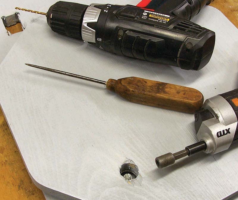
Figure 8. A hole drilled through the base coinciding with a hole in the Lazy Susan rim allows access to four screws used to mount the Lazy Susan to the caddy table.
There are four holes to mount the table. The base is rotated until the hole in the base is over a mounting hole, then a screw is inserted and tightened. The base is again rotated to do the next screw. Note the wooden pieces have been painted prior to installing the Lazy Susan.
Looking at Figure 9, there’s a small power strip that has been mounted to the plywood back plate using two flat head machine screws passing through holes drilled in the plywood.
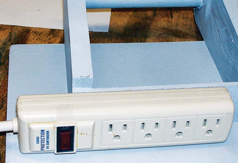
Figure 9. A small power strip is mounted to a plywood backing of the handle holders to give the instruments a place to plug into.
The instruments will plug into this power strip, which allows just one plug that needs to be plugged in for the instruments to operate.
To easily move the caddy around on the benchtop, I needed more than just bare wood. So, to this end, I installed furniture coasters on the bottom of the base. Looking at Figure 10, you can see where I placed a glider on each corner of the octagon.
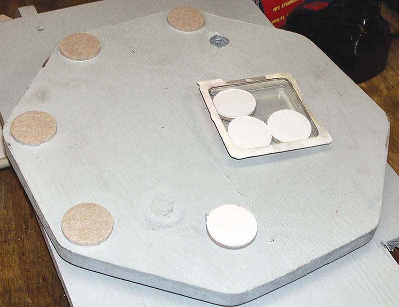
Figure 10. Installing glider pads on the bottom side of the caddy base so it’s easy to move on the bench top.
The gliders have an adhesive backing, so all you do is pull the protective paper covering away and stick it on. They hold on really well.
Finally, there must be some means to hold the stack of instruments on the caddy table when it’s moved. I chose a strap of Velcro™.
I found a roll of 3/4 inch wide tape for just a couple bucks at Walmart that worked just great. It easily cuts to length with a pair of scissors, then attaches to the table using a wood screw and a finishing washer (Figure 11).
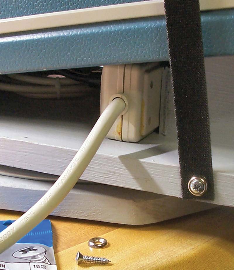
Figure 11. Anchoring the hold down strap used to hold the instrument cluster in place.
A short length is attached to one side with its ‘hook’ side up, then a length with the fuzz side down (doesn’t scratch the instruments) is stretched across the top of the instrument stack to firmly hold them in place.
This completes the oscilloscope caddy and is shown in Figure 12, ready to be put to work.
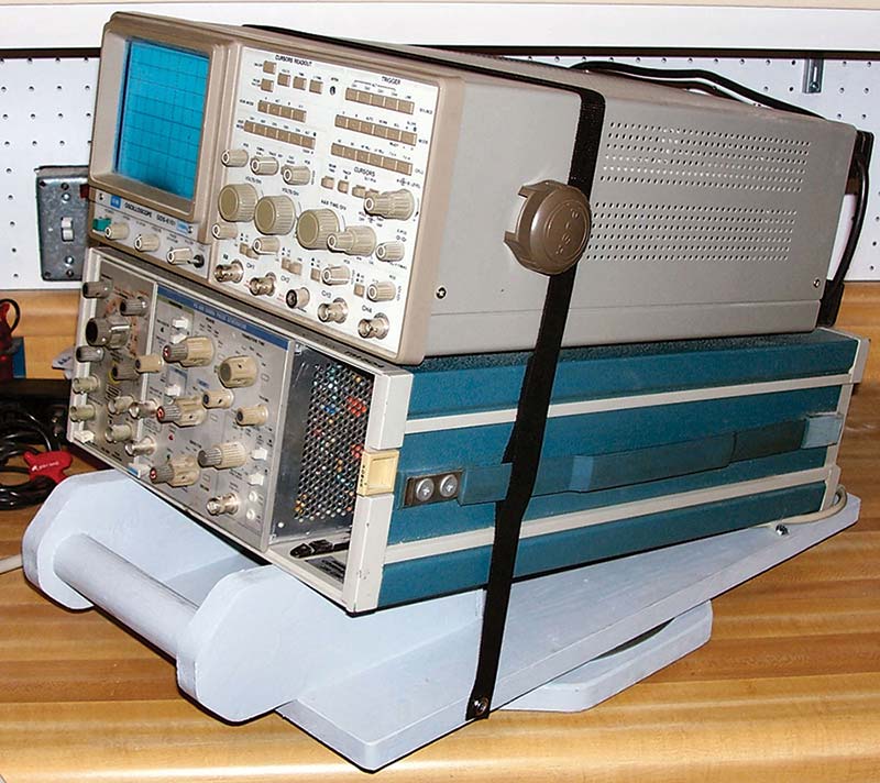
Figure 12.The completed oscilloscope caddy ready for use in my laboratory.
Another Caddy for the Wires and Boxes of My DSO
The caddy worked so well for my oscilloscope, I decided to see what I could do for my DSO (Digital Storage Oscilloscope) — a virtual instrument system with a laptop, boxes, and wires all over. All these parts are shown in Figure 13, which are heaped together to lay out the design of the caddy.
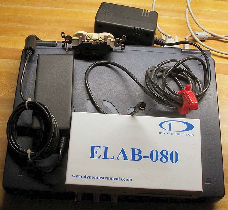
Figure 13. The various components that make up my DSO system.
The white box on top of the laptop is the virtual instrument; it’s an ELAB-80 which I have had and used for several years. I decided I wanted the laptop on top, where the screen would easily swing up for use with everything else underneath — out of sight and out of the way.
The length and width of the laptop defined the base, so I started with 1/4 inch plywood cut to size, including the 7/16 inch width of the wooden sides. From there, I could start piecing things together as shown in Figure 14.
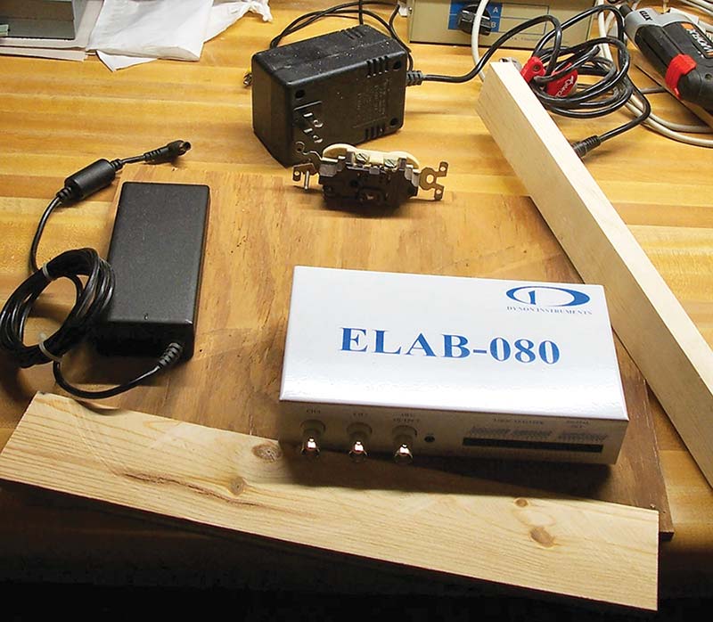
Figure 14. Doing the layout using the components to get as compact a caddy as possible.
The ELAB-080 has three BNC connectors and a long twin header for the logic analyzer, so the front side needed to have a ‘window’ for access to them. Once its position was determined, everything else would fall into place.
Looking at Figure 15, you see the cutout window for the DSO front panel to stick through yet have enough overlap to hold the instrument in place when leads are pulled out.
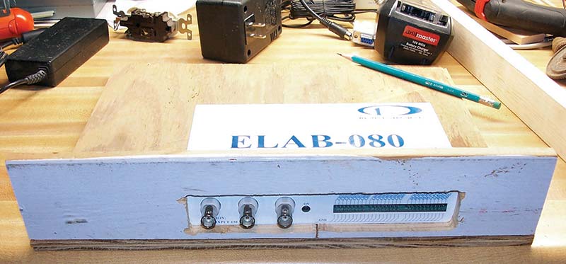
Figure 15. Window cut for access to the front of the virtual instrument.
The front side is glued and nailed onto the plywood base, sitting on top and flush with the base’s front edge, making sure the front is perpendicular to the base. Blocks or angle plates are used to hold the front perpendicular as shown in Figure 16 where two C-clamps on each end hold the block onto the base and the front onto the block.
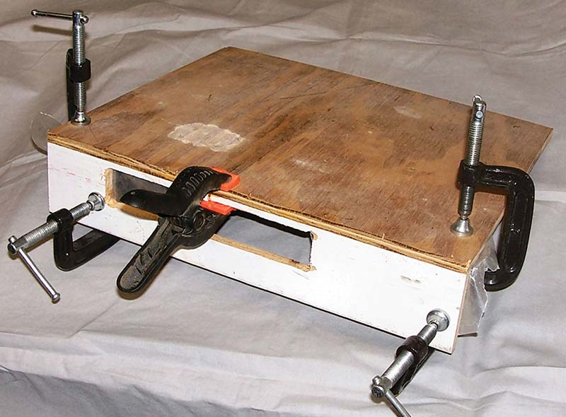
Figure 16. Gluing and nailing the front side to the caddy base using an assortment of clamps.
Place common wax paper around the block or angle plate to keep glue from sticking to it. A fifth clamp holds the center of the front side and base together to allow nailing with one inch wire brads. I let the glue joints sit over night to gain full strength before removing clamps and continue building.
The next step is to install the holding blocks inside the caddy. These are small wooden blocks glued and nailed to the base. First, cut some wooden blocks that are exactly the same height as the instrument. These blocks will hold the laptop above everything stored on the base.
Starting with the DSO pressed against the front side and centered on the window, glue a small wooden block on both sides of the instrument, then secure with C-clamps. Again, wrap the instrument with wax paper to avoid glue sticking to it (Figure 17).
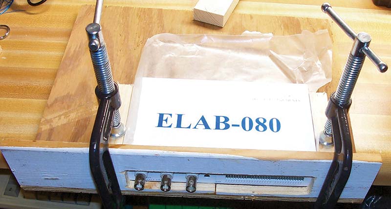
Figure 17. Installing the holding blocks onto the caddy base using the instrument to position them.
With the C-clamps pulled down tightly, you can pull the instrument out, turn the caddy upside down, and nail the blocks for added strength.
With the front side installed, place the laptop on its caddy position, then measure and mark the locations for any cutouts. Be sure and measure from the bottom up; you can also hold the side board against the laptop to mark it lengthwise. Figure 18 shows the right side marked with a pencil and ready to be cut.
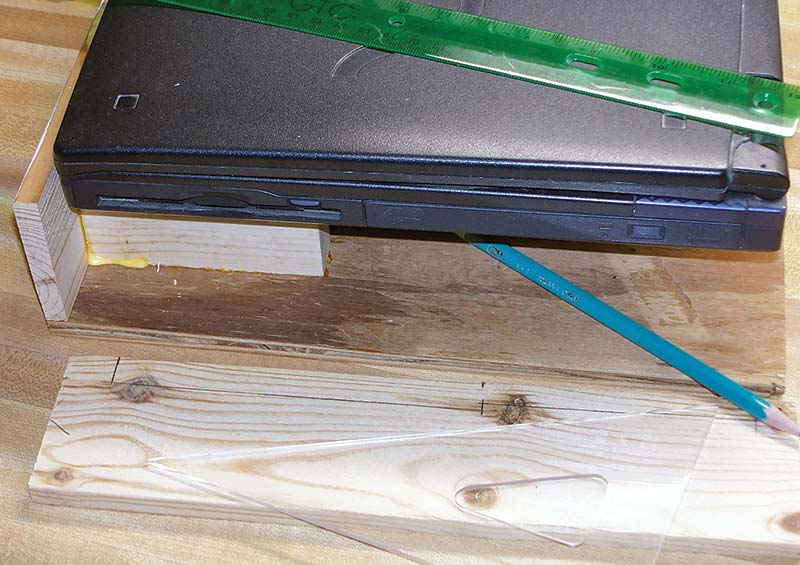
Figure 18. Layout and making the right side to install on the caddy base.
There’s a cutout for the 3.5 inch disk drive and one for the CD drive. Make sure there’s enough clearance to access each drive. Glue and nail the side the same as the front was installed.
Continue installing the other sides, position where the components will reside, then install wooden blocks to hold them in place. These blocks are the same height as the ELAB-080 and provide a spot for the laptop to rest on. Note where wires need to go when deciding where a component will go. The DSO uses a rather large wall wart for its power supply, which would set the laptop another 1-1/ 2 inches higher, so I elected to stick it out the back (top center of Figure 19).
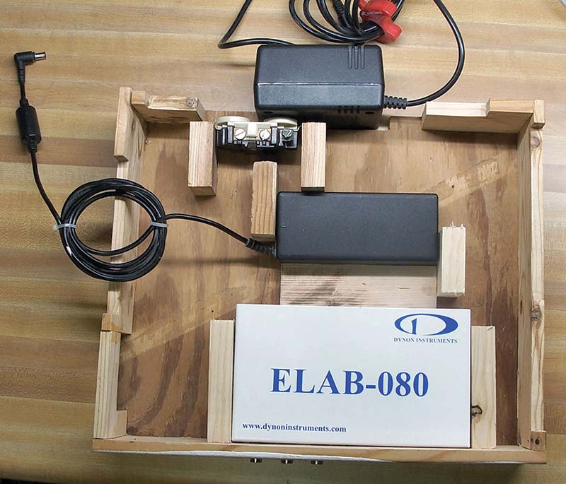
Figure 19. Add remaining holding blocks to the caddy base.
So, this defined where the AC duplex socket had to go. Once the wooden parts to the caddy are assembled, it’ll look pretty rough with all its joints and cracks. To make it look prettier, fill the cracks and joints with a putty as per Figure 20.
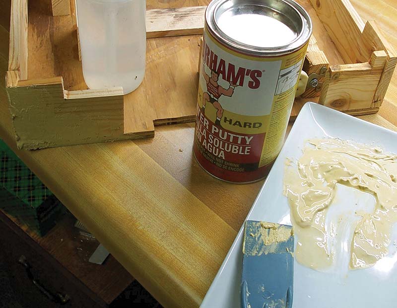
Figure 20. Using wood putty to finish the outside of the caddy.
For years, I’ve used Durham’s Water Putty for wood. It’s a fine powder that you mix with a small amount of water to get a putty whose consistency you can control so it’s best for your particular application. What’s great about it is it’s easy to sand it smooth and it doesn’t shrink! Just be careful with the amount of water; it’s easy to use too much, but you can always thicken it by adding a little more powder.
Use a putty knife to spread and smooth the putty over the cracks of the joints, let them dry, and then sand them smooth. The thicker the application, the longer it takes to dry; thinner applications take just a few minutes while a quarter inch application takes overnight
You have about five minutes to easily work the putty, so only mix what you can use in five minutes. With the putty dried, you can easily sand it smooth. Of course, no matter how careful you are smoothing the surface, you’ll still have low spots. So, just mix up more putty and spread on another layer. Being thin, the putty quickly dries and can be re-sanded to make a smooth surface.
Now you can paint the caddy with latex paint. Home improvement stores will mix half pint samples of their paint for around $4. You can check their paint chip display and select the color you want, and they’ll mix it up in just a few minutes as you wait. I always use a cheap paint brush so I can just throw it away and avoid the mess of clean-up. You can see how the caddy is painted on the outside in Figure 21.
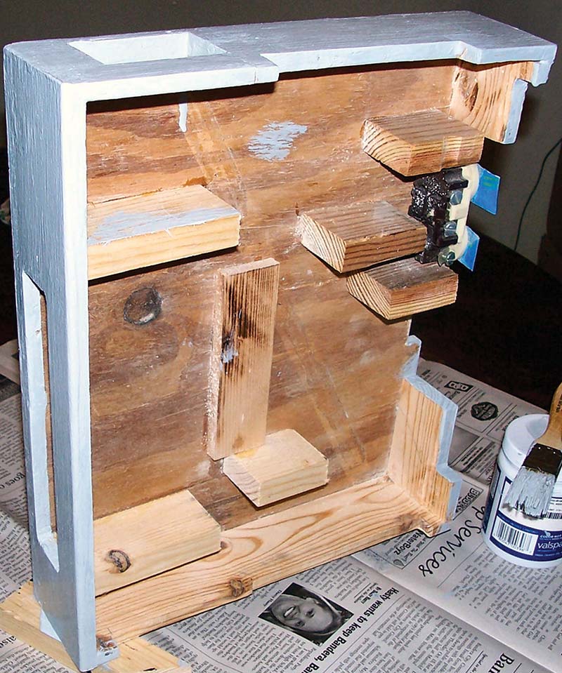
Figure 21. Painting the exterior of the caddy using latex paint.
Since there are multiple parts of equipment plugging into AC power, I wanted a single switch to turn the power on/off. I found a combination switch, fuse holder, and receptacle for the power cord at Jameco (#IEC-GS-1-100) which snaps into a sheet metal panel for under $5 (Figure 22).
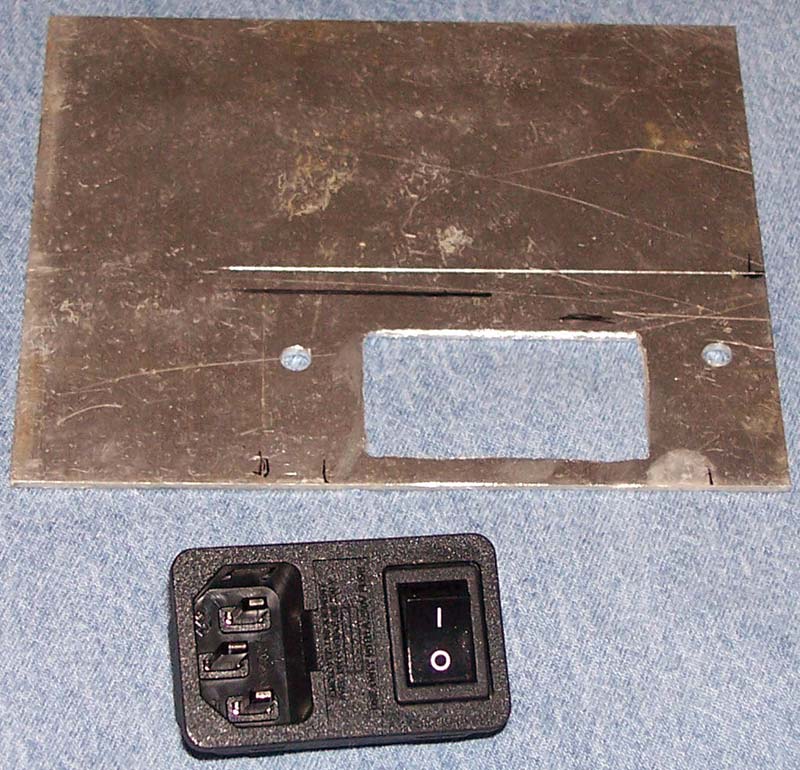
Figure 22. The AC power switch and its mounting plate to mount it on the caddy.
Jameco has a datasheet for this with the dimensions for the cutout. I used my CAD system to make a full-scale drawing of the cutout, then printed it out full size to use as a template for marking it. After cutting out the metal, you may need to file around the cutout to get the switch to slip in. Two through holes are drilled on either side of the plate so it can be mounted with short wood screws.
After cutting the mounting plate out from the sheet metal stock, it can be stuck onto a board with masking tape applied upside down. This allows the mounting plate to be painted with either a brush or spray paint as in Figure 23.
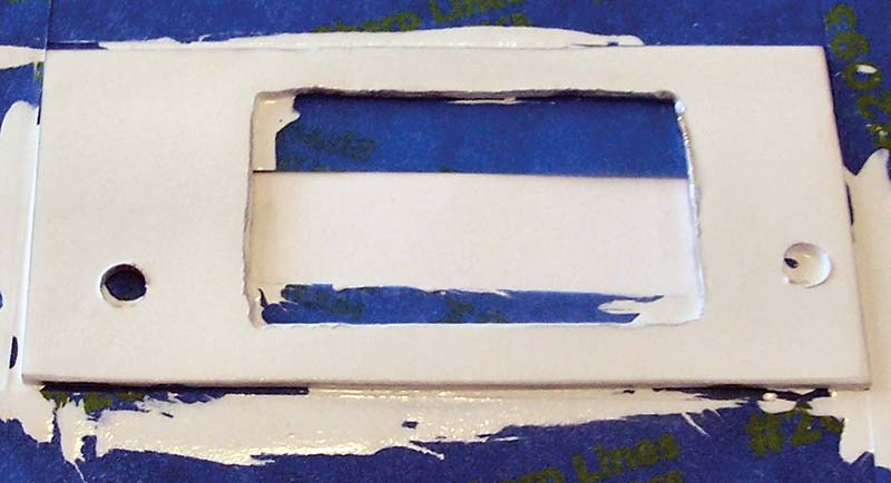
Figure 23. Painting the AC switch mounting plate prior to installing in the caddy.
After the paint is thoroughly dried, you can easily pull the plate off without leaving any fingerprints on the surface. Now the plate can be mounted on the wooden sideboard with the cutout centered on the window of it.
With the plate now mounted on the wooden side, the switch assembly can be pressed through the cutout until the four fingers snap open to hold the switch assembly firmly in place. Also, the duplex socket (where the electrical cords will plug in) is secured to the two wooden supports on the back side.
Now the caddy can be wired using AWG #14 solid wire that’s used to wire houses as shown in Figure 24.
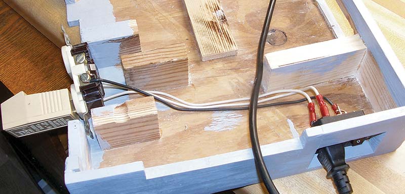
Figure 24. Wiring the caddy for AC electrical power.
I used crimped-on connectors for the switch and bent wire hooks on the other ends to connect to the duplex socket. A short wire is soldered between the fuse terminal and the switch terminal to carry electrical power over. Wires are then built up for connection by first installing the connectors, then each is pushed onto the switch assembly terminals. The wires are cut to length and finally installed on the duplex.
The circuit is tested with the same AC circuit tester used in Part 1 to make sure everything is wired correctly and can be seen on the left side of Figure 24. This completes the wiring.
With the wiring done, the various components are installed (refer to Figure 25), then the cables are routed and dressed so they clear the laptop when it sits on the caddy.
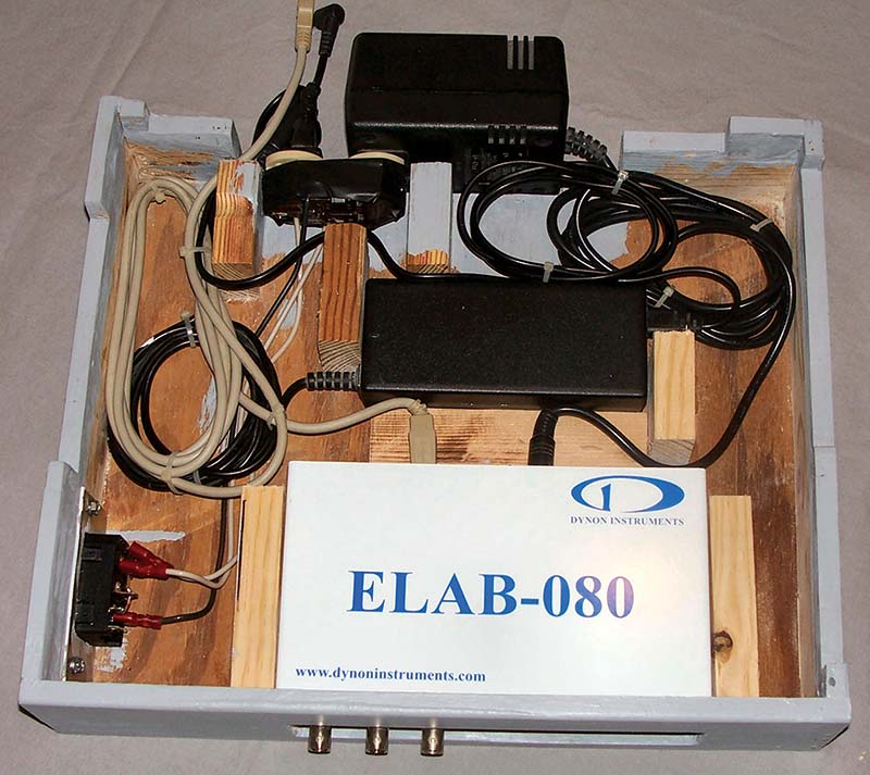
Figure 25. Installing the various components and dressing the cables.
Nylon tie wraps are used to dress the wires and hold them in position. Note how the wooden blocks hold each part in place and how the wire bundles are routed around these blocks. Two of the wires go out the back (upper left) to connect to the rear of the laptop. The laptop can now be installed by placing it between the four sides and gently pressing it down until it slips into place. The DSO caddy is now complete as shown in Figure 26.
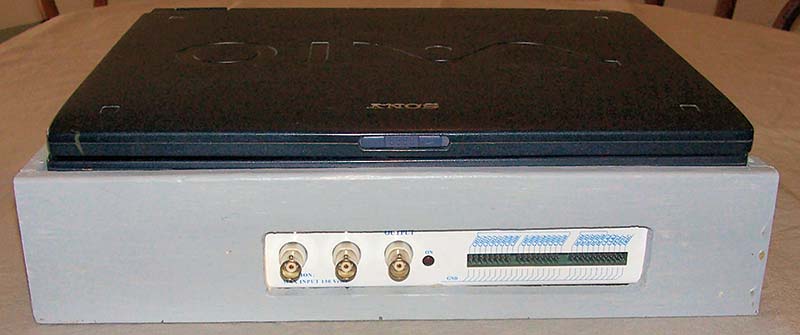
Figure 26. Laptop installed in caddy; the system is now ready for use.
Note how compact the unit is, and how the inputs/outputs of the ELAB-080 poke through the window of the front side, making everything easily accessed by the user. Looking at Figure 27, you can see how the cutouts work to allow access to the laptop’s connections, yet the sides come up enough to firmly hold the computer in place.
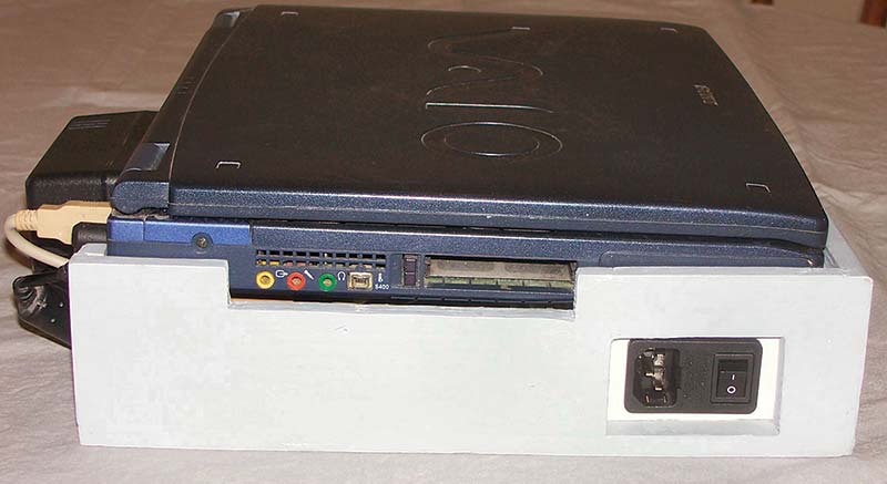
Figure 27. Side view showing cutouts in side board to allow access to laptop inputs/outputs.
On the lower right side of the figure, you can see the power switch and its connection for the power cord. Finally, Figure 28 shows the DSO caddy system up and running, in use but easily folded up and scooted aside to make room on the benchtop.
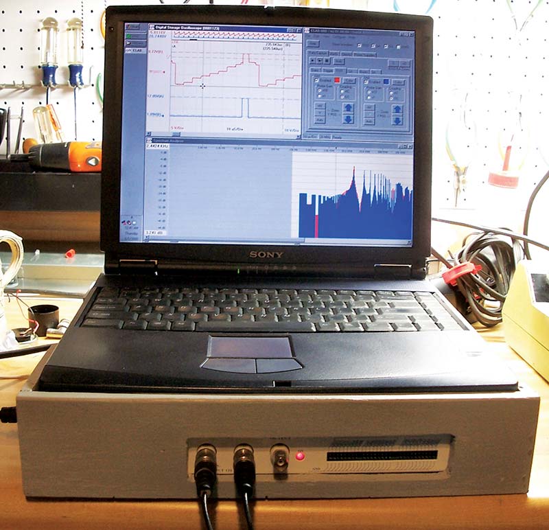
Figure 28. The DSO up and running, ready for experiments in electronics.
The Tool Box
Years ago, I found a really good wooden machinist tool chest on sale which I bought for my lab. I’ve used it ever since for the majority of my electronic tools. It’s worked great and has become a ‘must have’ part of my lab, but with my new bench, there was the question of where to put it. On my old bench, the tool box sat on a small table at the side of the bench, but now that was gone.
It’s a heavy tool chest, so it has to stay where I set it, and it was looking as if I’d have to set it up on the benchtop, taking up valuable space.
The tool box was temporarily sitting on a furniture mover’s dolly under the bench until I could decide what to do with it. I was telling my wife about my dilemma, and she made the absolutely brilliant suggestion, ‘Why don’t you just put it on rollers and scoot it in and out from under the table as you need it?’ So, that’s just what I did!
I built a custom designed cart that exactly fits the tool chest at a height that allows it to slide easily under the countertop. I had a length of 3/4 by 1/8 inch angle iron to build it with, which would be easy to weld together once the pieces were cut out. Since I wanted as much space below the tool chest as possible, I needed to precisely cut the steel to lengths.
Looking at Figure 29, you see it’s a simple frame box with coaster wheels underneath, where the angle iron is turned upwards on top so that it holds the tool box securely in place.
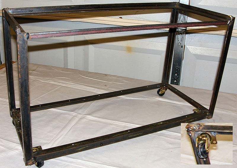
Figure 29. Frame for the tool box cart welded out of 3/4 inch angle iron. Note welding of coaster wheel in lower right corner.
The swivel coasters are also welded to the frame as seen in the photo insert in Figure 29, right lower corner. Make sure the castor wheel has sufficient clearance with the frame before welding them on. The structure is strong and stiff, despite its appearance. Looking at Figure 30, you can see I put a shelf on the lower part of the frame, made from a salvage shelf of 1/2 inch plywood that had a 1x2 support running the length of the shelf.
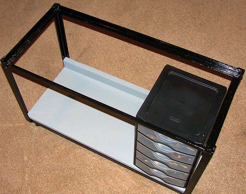
Figure 30. The frame painted with a plywood bottom shelf installed. The black cabinet has five plastic drawers for storing small items and instruments.
This meant cutting it down to size. I left the 1x2 support attached, turning the shelf upside down so the support acted as a back stop.
After painting it with some latex paint, I secured the shelf with wood screws. Note the plastic five drawer cabinet sitting on the shelf, which just fit under the tool chest and holds a zillion small electronic devices and instruments, including two other virtual instruments. There’s room for two more identical cabinets which helps immensely with storage and ease of accessibility.
The frame itself is painted with a glossy black enamel specially formulated for metal. These three cabinets are shown along with the tool chest sitting on the frame of the cart. Figure 31 shows the completed tool cart ready to be put into service.
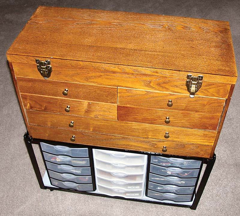
Figure 31. The completed cart with the tool chest sitting in place and the plastic drawer sets, ready for use.
The tool chest has the side drawers with various hand tools (four small sizes and two large), plus the top lid swings up for more tool storage for larger tools.
So, it’s all set at a convenient height when sitting at the bench working on something. The tool cart is shown in use in Figure 32.
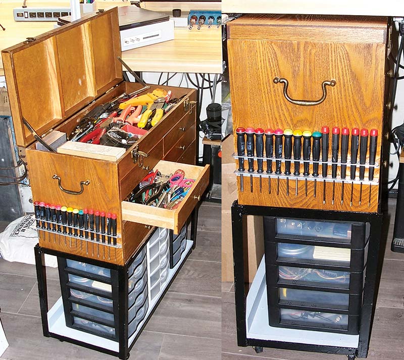
Figure 32. On the left, the tool chest is out and open for use, while the right side shows it pushed under the bench out of the way.
The left side shows it out and open by the bench ready for use, while the right side shows the cart pushed under the bench out of the way.
Note the line of precision screwdrivers on the side of the tool chest within easy reach. I made the holder by drilling two lengths of 1/2 by 3/4 inch angle aluminum from the hardware store. The handle on the end of the tool chest works great to push and pull the cart for placement.
Under Bench Computer Drawer
The final accoutrement for my lab bench was a ‘slide under the bench’ table for the keyboard of my Internet computer. Making sliding drawers and tables once was a difficult preposition; that is, for ones that slide in and out smoothly without jamming.
A product called Euro Slide that can be found at most building and hardware supply stores turned this around, making drawers easy to do. Looking at Figure 33, you see a set of slides for a 12 inch deep drawer as well as the instruction sheet.
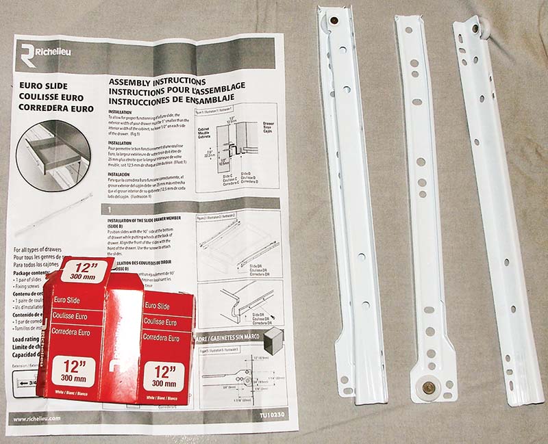
Figure 33. The parts of the rail slides used to make the drawers, consisting of rails with rollers that help a drawer to easily slide in and out.
There are two rail sets: one for the right side of the drawer and one for the left.
In the figure, the left rail set has the two parts assembled to form a slide track, while the two on the right show the slide apart. The center part is the slide rail that attaches to the side of a cabinet. Note the roller on the end of the rail (bottom of picture).
On the right side of Figure 33 is the rail that goes on the bottom of the drawer. It’s L shaped, with a curve channel on the opposite edge (rightmost side of the picture) and a second roller on the end (top of picture). In use, the flat side goes under the drawer and is attached with small screws, then the curve channel of the drawer rail will slide on the cabinet rail’s roller while its roller slides in a channel on the cabinet rail.
Therefore, the two rollers support the weight of the drawer and its contents; yet with a slight pull, the drawer slides smoothly out or returns inside the cabinet.
The keyboard tray is, in fact, an open drawer that uses these drawer slide rails like any other drawer does. So, the first step is to define the size of the drawer. It needs to be wide enough to accommodate the full length of the drawer rail (12 inches), then the tray’s length needs to be sufficient for my keyboard and mouse.
Therefore, I started by cutting a section of 5 mm Lauan plywood 12 inches wide and a little longer than anticipated for the tray; in this case, 24 inches.
The bottom of the tray is laid on the bench, then the keyboard and mouse are positioned with enough clearance to easily grasp the mouse. The layout is shown in Figure 34, with the drawer rail on the extreme left edge, barely visible because the plywood is almost white.
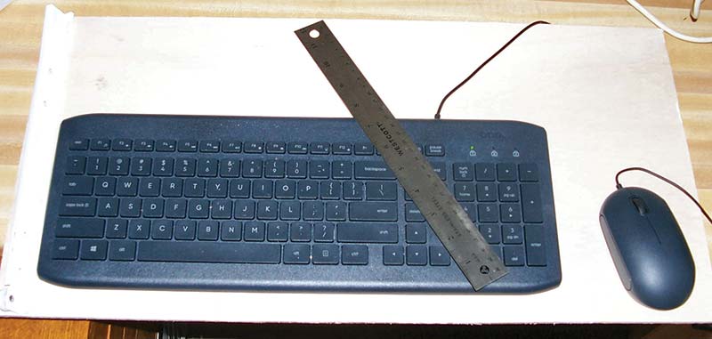
Figure 34. The plywood bottom of the tray with keyboard and mouse on top to lay out the dimensions of the keyboard tray.
A pencil line is drawn where the plywood is to be cut.
Once cut, the two end pieces are cut to length, then glued and nailed flush with the edge to the plywood. For the end pieces, I used pine wood ripped from a 2x4 that was 7/16 inches wide. This was the perfect height so both the keyboard and mouse cleared the bottom of the countertop.
Again, angle blocks and C-clamps are used to glue and nail the ends to the table bottom. Looking at Figure 35, note the slips of wax paper used to keep the glue from adhering to the angle blocks.
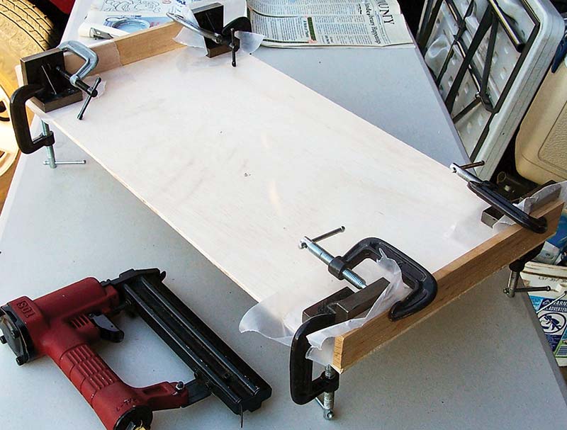
Figure 35. Gluing and nailing the two end pieces onto the tray’s bottom using angle blocks and C-clamps.
It’s left overnight to let the glue joint gain full strength.
Since the tray’s bottom is just 5 mm thick, I stiffened it by gluing a 1/4 inch square bass wood strip (Hobby Lobby) onto the forward edge of the tray as seen in Figure 36.
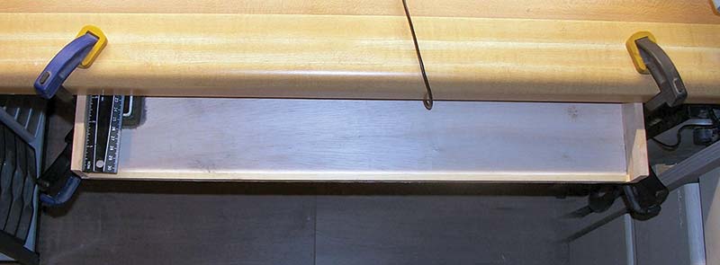
Figure 36. A slot must be cut in the plywood so the tray will fit fully under the bench. It’s positioned, then held under the bench using clamps.
Because the steel angle support of the bench frame interferes with the tray sliding fully back under the bench, there needs to be a slot in the plywood tray bottom to pass that steel support.
Notice the ruler on the left side of the tray. This is used to measure the distance the tray must travel past the steel support and therefore be under the benchtop.
This distance is how deep the slot must be cut so it will pass the steel support. To measure, the tray is positioned where the back edge is against the steel support, then held there using two bar clamps, one on each end. Now the position of the support can be marked with a pen by simply ducking under the bench and marking it.
The slot for passing the bench frame is next sawed out of the bottom, which is easily done with the thin plywood. I also added a second stiffener: a 3/4 inch square wooden support glued and nailed across the tray just back from the slot. With that done, the tray was painted with the same latex paint used in the other bench projects.
It’s time to install the slide rails on the bottom of the tray, since these are needed to measure and construct the frame that will hold the tray up under the bench countertop.
Looking at Figure 37, you see the slot cut in the bottom (upper right corner) and one rail installed on the right side.
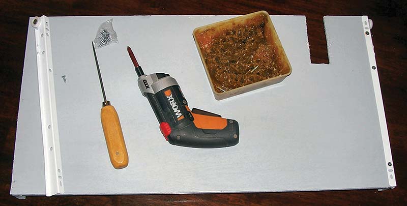
Figure 37. Installing the slide rails to the bottom of the keyboard tray after cutting the passage slot and painting.
The other rail is ready to install (left side of figure) with an ice pick used to start the screws.
Beside the rail is one of the screws that comes with the slide set, which are #6 wood screws just 3/8 inches long with three screws for each rail part. With the rails installed on the tray, the next step is measuring the side members that hold the tray in place, including the other two stationary rails.
The side members are cut to the same length as the side rails, then a notch is cut on the upper ends, so the countertop overhang will not prevent the side members from lying flat against the counter bottom.
To attach the side members, a strip of thin plywood it glued and nailed to the tops of the side members making attachment wings that are used to attach the side rails to the countertop’s underside.
The keyboard tray is attached to the bench using screws through the plywood wings.
Figure 38 shows the now painted side members with the slide side rails being attached with screws.
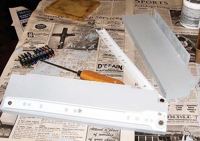
Figure 38. The side members used to hang the keyboard tray down under the bench top, with the slide side rails being attached.
Note the rails go on the opposite sides of where the plywood supports or the wings stick out. The next step is fitting the slide rails on the drawer to the side members to adjust the spacing.
To install, the spacing of the side members must be established using the keyboard tray with the slide rails engaged to slide. I took a scrap of wood and secured the side rails with two C-clamps as shown in Figure 39.
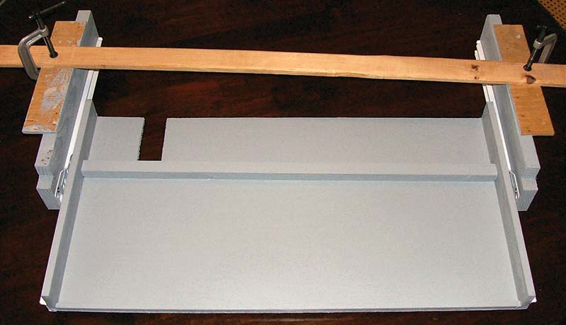
Figure 39. Adjusting the spacing of the side members so the tray slides in and out smoothly prior to being installed.
This arrangement allows you to adjust the spacing, so the tray slides in and out without scraping and without jumping the rails and binding. Note that the keyboard tray is shown partly extended with the two cross-wise stiffeners visible; one on the front edge and the other back against the slot.
Once the spacing is established, the whole affair is carefully turned upside down so temporary supports can be installed allowing the whole assembly to be attached to the bench. Using a couple of scrap pieces of lumber, they are positioned as a ‘V’ (Figure 40) to also give cross bracing that prevents rotation of the rectangular structure into a parallelogram.
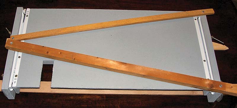
Figure 40. Using two lengths of scrap lumber positioned as a V for cross bracing, secured temporarily with hex head screws.
I used hex-head sheet metal screws (one on each end) to temporarily hold the supports in place, but can easily be removed once the keyboard tray is installed. The clamped-on wood support that was first installed can now be removed so the tray will fit up against the countertop’s bottom side.
With just the V support in place, the keyboard tray is installed under the bench by holding it in place, then installing six screws through the two plywood wings into the countertop. Here’s the rub: Trying to hold that assembly in place while drilling pilot holes, then screwing in the screws with an electric screwdriver is not trivial!
Despite a number and wide range of clamps, I just didn’t have a clamp with a deep enough throat to hold that tray in place. I had to rely on my wife to hold it for me, but she couldn’t get in a position to hold it well, so it was a real struggle.
Once the mounting screws were finally installed, the four screws holding the V support in place are removed, leaving the tray installed and ready to use. Figure 41 shows the completed keyboard tray pulled out and being used.
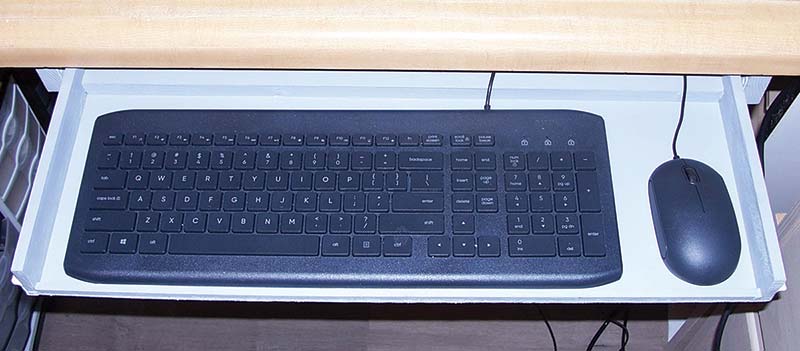
Figure 41. The keyboard tray now installed under the bench and pulled out for use. When not being used, it’s simply pushed back under the bench top out of the way.
The mouse is actually moved over to the corner of my desk when in use.
Well, that completes the dozen enhancements I made to my new electronic laboratory bench. Hopefully, there’s some ideas here for things you can make and do for your lab. Maybe not a complete thing I’ve described, but maybe bits and pieces from several projects combined to give you something new to add to your work bench, thereby making it better. Just keep in mind, that if you can build robots, computers, and radio receivers, then you can build any of these projects. Just be careful not to violate the P6 law.
So, now the adventure begins! A return to the fun and joy of electronics and robotics now that I’m back in the saddle. And this time, doing the fun things I want to do.
However, I first need to calibrate my instruments. Something I haven’t done in years! SV
Article Comments