Designing a New Workbench for Your Robotics Hobby Phase 2A
By James Lyman View In Digital Edition
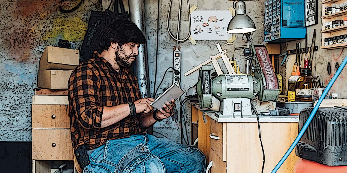
With the frame and countertop completed, the next phase is building several accoutrements and accessories to enhance using our new robotics lab.
With the bench completed, it’s time to build all the little accoutrements and accessories to make the bench more useful. I built about a dozen things for the bench; each was a small project unto itself — some very easy, others more complex. You may be able to use one or more of these mini projects on your lab bench ‘as-is,’ or their descriptions may spark some ideas of your own. Some are just a continuation of the bench building to finish it up, while others are unique stand-alone projects that you can use part of or all in your lab.
So, let’s look at each one and see if there’s anything you can use. For the most part, they’re easy to build. Also, there are some construction techniques that you might find interesting and useful. So, enjoy.
Installing the Top Shelf
I designed the bench frame with a top shelf which I salvaged from my old lab; hence, the top horizontal projection of the frame. It’s just wide enough for that salvaged top shelf to fit on. With the frame and countertop done and electrical installed, the first thing I did was install that shelf since it was the easiest thing to do. Plus, it just sat there on top with no need for fasteners.
The shelf was a shade too long, so I had to cut a little off each end. I wanted to use this shelf because it has edge extensions installed on each end that made it perfect for my stereo speakers as seen in Figure 1.
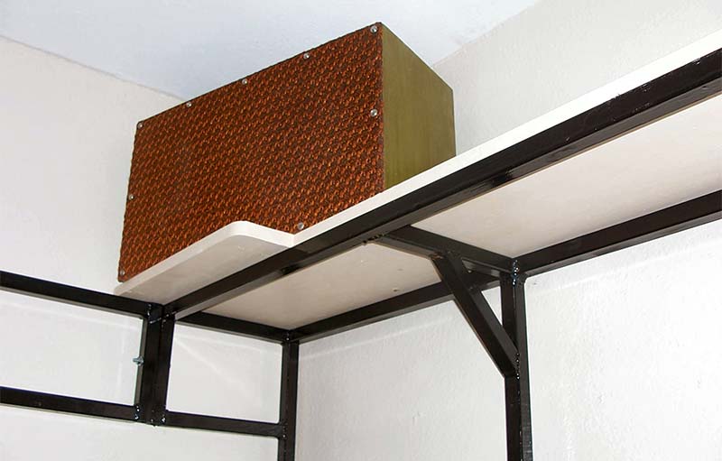
Figure 1 - Sitting on the top of the bench frame is an 11-1/2 inch wooden shelf used for general storage. There is no attachment needed to hold the shelf on.
These are speakers I designed and built back when I was in college. I used 3/4 inch plywood — back when you could still afford to buy it. Fifty years old and they’re still going strong and sounding great. Anyway, for all these years, those speakers have sat on top of my lab bench, connected to my little lab stereo. Because you know, your work just goes easier when there’s nice music to listen to.
Music to Work By
Speaking of music and stereos, the stereo set I had for years in the lab finally gave out a year ago. Looking around, I couldn’t find a suitable replacement (a small amplifier with a built-in CD player). While pawing through one of my electronic junk boxes, I came across a 12 volt, one amp power supply that I built a few years ago and that gave me an idea.
I went to Walmart, and sure enough, I found just what I needed (Figure 2) at a price I could afford.
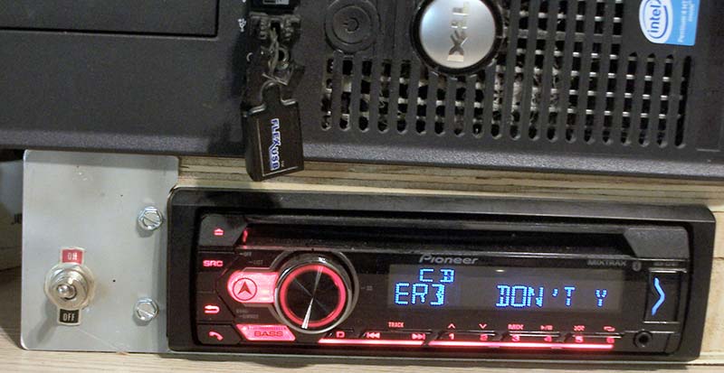
Figure 2 - Use a low-cost car stereo in the lab for some music while you’re working.
I bought a Pioneer stereo for cars with a CD player as well as MP3 player input and USB thumb drive.
I made a little wooden box where the stereo would slip into, with the power supply sitting in the back and my computer on top. Worked perfect!
So, if you want a little music to work by, consider getting a car stereo and (if need be) build up a simple 12 volt power supply to operate it. Music makes the treat of working with electronics just a little more joyful.
Power for the Top of the Bench
While all my instruments plugged into the AC power under the bench, there are times when you need to plug tools, lights, or equipment being tested into AC power. The instruments are plugged in, then left — often for years on end — but it would be inconvenient to crawl under your bench to plug in something like an electric drill that you use for an hour or a day, then crawl back under again to unplug it.
I had a couple of ‘old school’ power strips from way back that are made of sheet metal instead of plastic, which I considered would be ideal for providing easy access AC power to the benchtop. The metal case has a metal tab or ear on each end (Figure 3) where a hole can easily be drilled for mounting it.
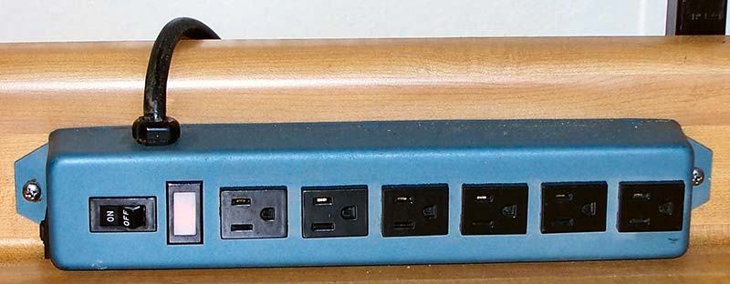
Figure 3 - Conventional AC power strips can be mounted on the bench top to provide power receptacles for plugging things in when being worked on.
Holes were drilled in the countertop backboard, so the power strip is mounted using two 10-24 machine screws with nuts on the back.
The mounting holes were first drilled in the power strip tabs, then held in place on the counter backboard where it will be mounted. The same size holes are drilled through the wood of the countertop. I used a clamp to hold the power strip in place while drilling, so the holes would match up. I positioned the strips so the power cord went over the backstop of the countertop to plug into the power underneath. Figure 4 shows the screw through the tab holding it securely in place.
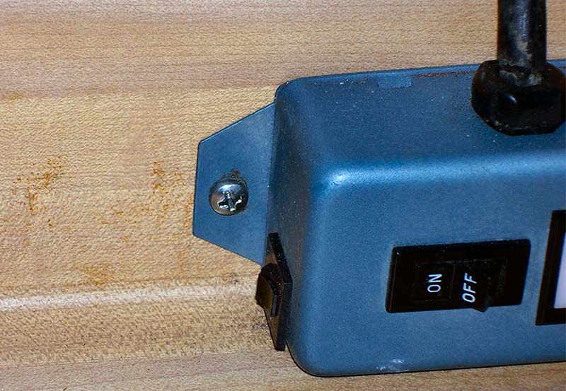
Figure 4 - The power strip mounting with machine screws.
The power strips were in such a convenient place that, from the start, I was using them while constructing the other parts of the bench.
Pegboard to Hold Your Tools
I was able to salvage the pegboard from my old shop. It was a double benefit because I was also able to use its stiffeners with only some minor modifications. Looking at Figure 5, you can see the stiffeners framing the pegboard’s back.
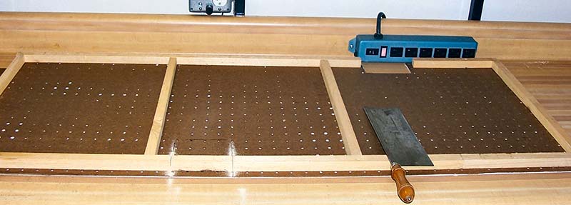
Figure 5 - The pegboard has wooden stiffeners glued and nailed to the backside to prevent the load from warping the board once in use.
These stiffeners are 3/4 inch pine boards cut by ripping 3/4 inch wide strips from 1x4 or x6 or x8 boards, which themselves are 3/4 inch thick.
These 3/4 inch square wood strips are attached to the back of the pegboard with wood glue and 3/4 inch wire brad nails. First, I go around the perimeter of the board, then do vertical strips every 24 inches. Being 3/4 inch on a side, they fit perfectly between the holes so the hooks can still be inserted in the board without obstruction. Indeed, you can use hooks inserted in the pegboard to act as guides in aligning the stringers prior to gluing and nailing.
The 1/8 inch Masonite hard board (that pegboard is made of) flops around like the proverbial wet noodle. If hung up without these stiffeners, the pegboard sags and pulls away under the weight of things hanging on it. With a little effort, these stringers turn pegboard into a very useful storage device, able to support surprisingly heavy items.
Because of the steel frame, there was a lot of cutting and modifying to get the panel to fit. This was accomplished with a small handsaw such as the cabinet saw in Figure 6, plus an electric rotary tool with a small circular saw blade shown in Figure 7.
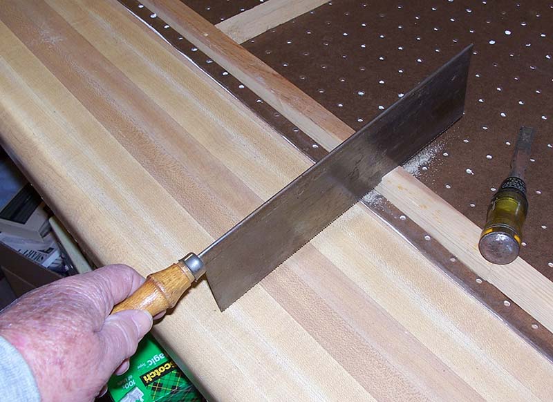
Figure 6 - Using a cabinet saw to make cutouts of the pegboard stiffeners.
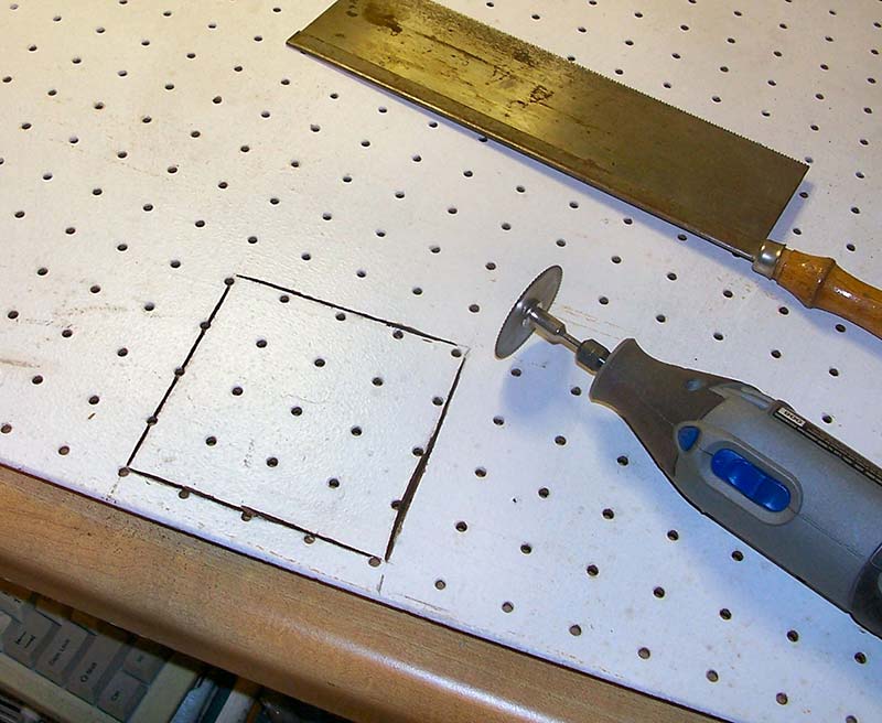
Figure 7 - An electric rotary tool with a circular saw blade is used to make cutouts in the pegboard for the electrical box to fit through.
I used these on the cutout for the electrical power switch. Finally, holes are drilled to pass the bolts used to mount the shelf brackets to the steel frame, which also hold the pegboard onto the frame. Figure 8 shows how the bracket fits on the frame upright.
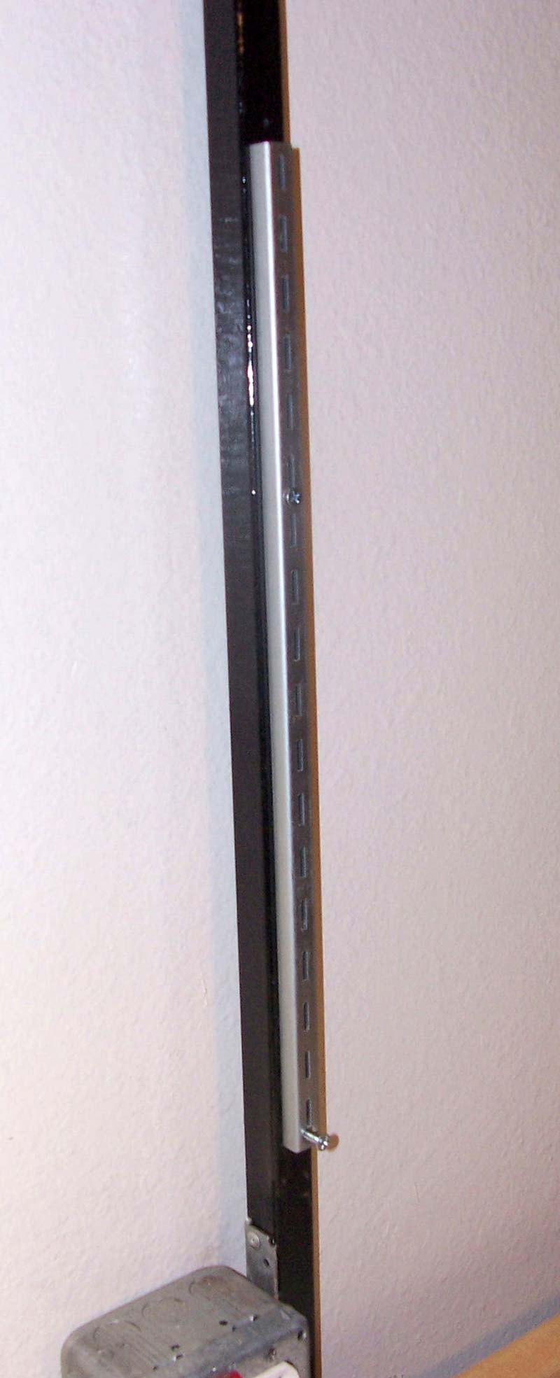
Figure 8 - Shelf bracket used to hold the pegboard on the frame.
Unfortunately, the dark near-black surface of the pegboard is a sponge for light, so it soaks up your light over the work area of the bench. To resolve this, I painted the outer surface white.
While the salvage board was already painted white, it was old and dirty with several holes and gouges. I used spackling compound (found in any store with painting supplies) to spread over any holes or gouges on the surface of the board, then smoothed them flush with a putty knife to dry. Of course, a smoother finish can be made with a little sanding.
Painting pegboard is rather troublesome because the paint is constantly filling in all the small holes. I use a one inch wide brush to go between the holes, dipping just the tip of the brush in for a small amount of paint. Carefully spread the paint out in a thin layer.
If you’re painting new pegboard, you’re going to have to do two coats, so don’t make a lot of work for yourself by trying to do it with one coat. Nevertheless, you’re going to get paint in some of the holes, but you can use standard pipe cleaners to clear them out while the paint is still wet; refer to Figure 9.
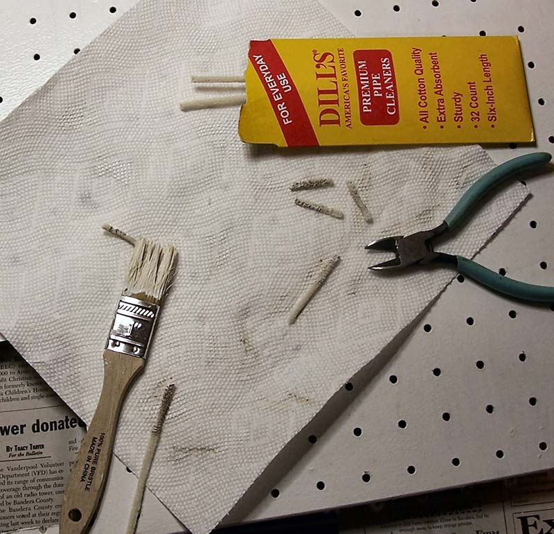
Figure 9 - Painting the pegboard with white latex paint.
Paint a small section at a time; in this case, about 6x16 inches, then take a pipe cleaner and insert it into the filled hole, slowly twirling it while pulling/pushing it in and out of the hole. This spreads the paint around the hole interior, plus scrapes excess paint off around the hole’s bottom edge. You don’t have to get every last bit of paint out; remember that latex paint shrinks when it dries. The pipe cleaner will soon become filled with paint, so use a paper towel to dry some off until you’re ready to continue with a ‘fresh’ pipe cleaner. You can do this about six or so times before you actually have to get a whole new pipe cleaner. It’s tedious, but just work steady, and you’ll soon be done.
With larger panels of pegboard, use a small paint roller, taking care to keep the roller fairly dry. Again, you’ll need to do two coats, and again, you’ll have paint getting in the holes, but just use the pipe cleaners. Once the paint is dry, the pegboard assembly is fitted to the steel back frame where it will be installed. Now is the time to do any additional trimming to make it fit properly. Figure 10 shows how it fits in, sitting snugly on the top edge of the countertop and not slipping down.
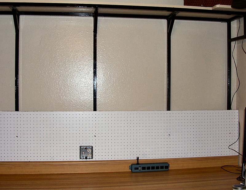
Figure 10 - Fitting the pegboard onto the steel back frame prior to mounting.
Once you’re satisfied with the fitting, it’s time to secure it to the frame. The pegboard is attached using two inch 10-24 machine screws and nuts. However, the problem is where to drill the thru hole in the pegboard. I use the shelf brackets to mark them. The holes in the steel tubing are already drilled, so a shelf bracket is hung with a bolt through the top hole, then allowed to hang downwards so the lower hole of the bracket marks where the thru hole will be drilled in the pegboard. These thru holes are a little larger than the thru holes in the steel frame to avoid alignment problems. You can remount the brackets as described in the next section.
Hanging the Shelf Bracket Rails
Next, we install the shelf brackets because they are also used to hold the pegboard on the steel frame. These brackets are for holding shelves using a slotted railed (Figure 11) where the support bracket hooks onto the rail so a shelf can lay across brackets.
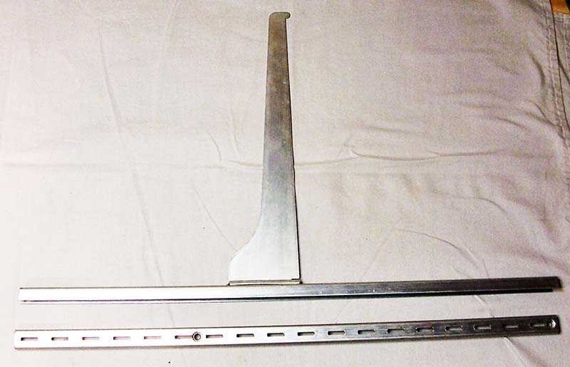
Figure 11 - The bracket and rail used to hold the shelves on the bench back. Note that the shelf height is adjustable using the slots along the rail.
The thru holes for the mounting machine screws were drilled during the cutting of the steel before the welding was done. Since the rails are also used to hold the pegboard onto the bench frame, the upper part of the rails must have a spacer under it to compensate for the thickness of the pegboard.
Looking at lower left corner of Figure 12, you can see a dark strip which is the spacer laying on the benchtop.
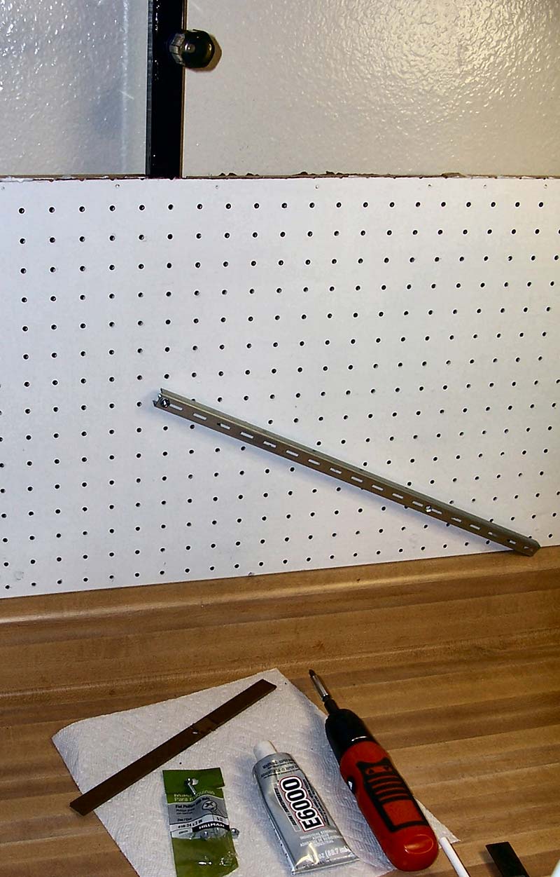
Figure 12 - Mounting of the rail calls for gluing a 10-24 nut on the back of the steel frame over the thru hole. Pictured is what’s needed for mounting the rails.
This strip was cut from a scrap of pegboard just a bit wider than the rail. Additionally, when the bench is up against the wall, you may not be able to get behind the pegboard to start the nut. So, use a dab of glue to attach it to the back frame.
The first step is to loosely mount the rail over the pegboard using the lower screw, so it can swing off to the side. I use two inch 10-24 machine screws and nuts. The thru hole for the upper bolt is marked on the Masonite spacer for where it is drilled. Putting a few dabs of clear general-purpose cement on the back of the spacer prevents slipping. Swing the rail up, insert the screw, and tighten both bolts. Note that the bracket slots must all align horizontally so the shelf will sit level.
Once the rails are mounted, securing the pegboard with screws can be completed. For this, I drilled and tapped 1/4-20 threads in the steel tubing so screws could be inserted directly without the need for nuts. Figure 13 shows the drilling and tapping through the pegboard of the steel tubing behind it.
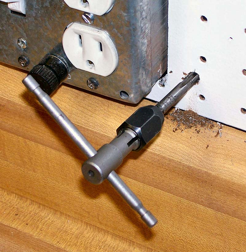
Figure 13 - A 1/4-20 NC tap is used to make threads in the steel back frame so screws can hold the lower part of the pegboard firmly against the bench back.
Now, I have a full SAE tap and die set, but over the years I’ve found that you only use a few taps in electronics. You can buy a tap and the tapping drill bit in a package at most hardware stores for $5 to $10, thus avoiding buying both a tap and die set and a set of wire gauge drill bits. Figure 14 shows a 1/4 inch pan head screw that secures the pegboard without using a washer.
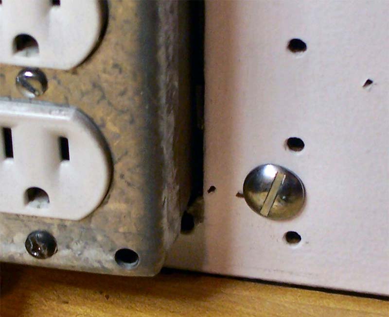
Figure 14 - A quarter inch pan head screw is used to secure the pegboard.
I happened to have a couple hundred of these 1/2 inch long screws that was given to me years ago. The pegboard was securely held with just the bracket rails and probably would have been alright, but I had the screws and tools, and it only took a few minutes to install and ensure the bottom didn’t pull up when taking out a pegboard hook.
When tapping a new thread hole, it’s important to remember the ‘quarter-half’ rule to avoid breaking a tap. Once the tap starts to bite into the metal, you turn the tap a half turn into the hole, then back it out a quarter turn to let the metal chips break loose. Then, turn the tap another half turn. Repeat this quarter-half turning process until the tap turns freely, which prevents the metal chips from binding the tap and possibly breaking it.
These taps are made of very hard steel able to cut metals such as mild steel, so they are very brittle. If you twist them too hard, they will snap … and getting a broken tap out of a hole is usually impossible, so you’ll have to throw away your work and start over. Normally, you’d squirt light oil (such as 3-in-One oil) on the tap to flush out the chips, but the 062 steel tubing is thin enough that the chips aren’t a problem.
A Shelf for the Instruments
The whole purpose of an electronic bench is to have a place to put your electronic instruments so you can use them in your work. The trouble with just setting your instruments on your benchtop is that they are in the way of your workspace. The answer is a shelf where your instruments can sit — all in a line above your workspace — so they’re always out of the way.
Because my board was salvaged from another bench, it wasn’t wide enough to span the shelf brackets, so needed to be extended. This was accomplished by attaching a 1x2 board on the back edge of the shelf using glue and screws as seen in Figure 15.
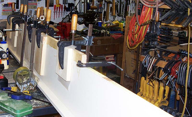
Figure 15 - The shelf for the instruments with a wooden extension being added to the basic shelf. Clamps are used to hold them together so they are aligned correctly.
Since the extension is 1-1/2 inches across, it’s secured with 2-1/2 inch screws. This means pilot holes must be drilled with countersinking. Looking at Figure 16, you can see a screw pilot bit being used to drill the hole and countersink (so the screw head is below the board).
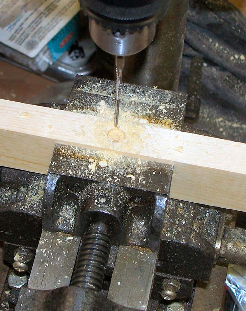
Figure 16 - Pilot holes are drilled through the wooden extension using a countersink bit.
I put a screw every 12 inches along the 10 feet length of shelf. While I used a drill press, you can easily use a hand electric drill to do the same thing. Referring again to Figure 15, you can see the extension board being glued and clamped into position. Short lengths of boards are clamped against the shelf to form an edge so the shelf and extension mate seamlessly together. Use common wax paper between the short boards and the shelf boards being glued so they don’t adhere to the guide boards.
Once the pilot holes are drilled in the extension board, spread wood glue along the length of the shelf board edge. If you have some bar clamps, use them to press the shelf and extension together before screwing them together. Otherwise, just rely on the screws pulling them together, being careful to keep the boards aligned to form a smooth surface.
Still, you may want to use some wood filler to fill in the seam and maybe some dents. Since I was using salvaged lumber, there were lots of ‘filler spots’ on the two boards. I use Durham’s Rock Hard Water Putty (any hardware or builder supply) where you scoop out a bit of fine dry powder, add some water, and mix. Then, use a putty knife and spread it out smooth. If it’s too thin, just add a little more powder. This stuff smooths out easily, sticks good, doesn’t shrink, and easily sands to a smooth finish.
My salvaged board had a 1x2 glued and nailed lengthwise on the edge to form an L to act as a stiffener so the shelf could support more weight over a four foot span. I didn’t need the extra support, but I wanted to put lights under the shelf to help with illumination over the work area. If I turned the bench upside down, the 1x2 would act as a light shade. This would turn out to be an important factor.
I found a great deal on LED lights (Figure 17) used in place of a standard 40 watt fluorescence bulb that is not only smaller, but much lighter and is super bright with 5,000 lumens for 30,000 LED hours of life.
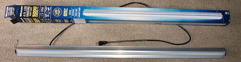
Figure 17 - The LED light fixture used instead of standard 40 watt fluorescence light fixtures, including the box it came in.
I wanted to mount the light flush on the bottom of the shelf, but there was an obstacle. Its power cord comes straight out the fixture’s top (Figure 18), just where the shelf was.
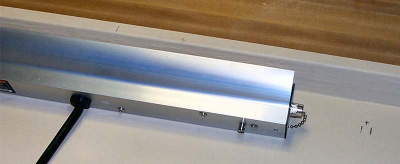
Figure 18 - Locating the position on the shelf underneath prior to attaching the LED light.
The cord is a thick stiff one, plus it has a strain relief as seen in the close-up of Figure 19.
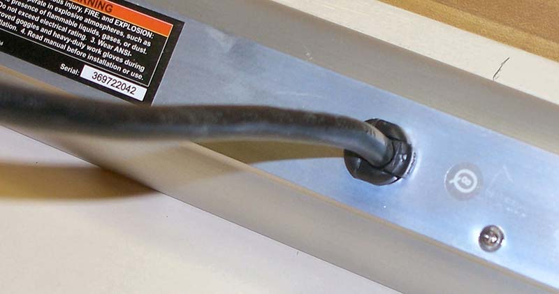
Figure 19 - Power cord attachment to the LED light.
To accommodate the power cord so it can turn and run flush with the shelf bottom, a groove needed to be cut into the shelf’s wood. I started by carefully drilling a series of 5/16 inch holes in a line and marking off the holes as shown in Figure 20.
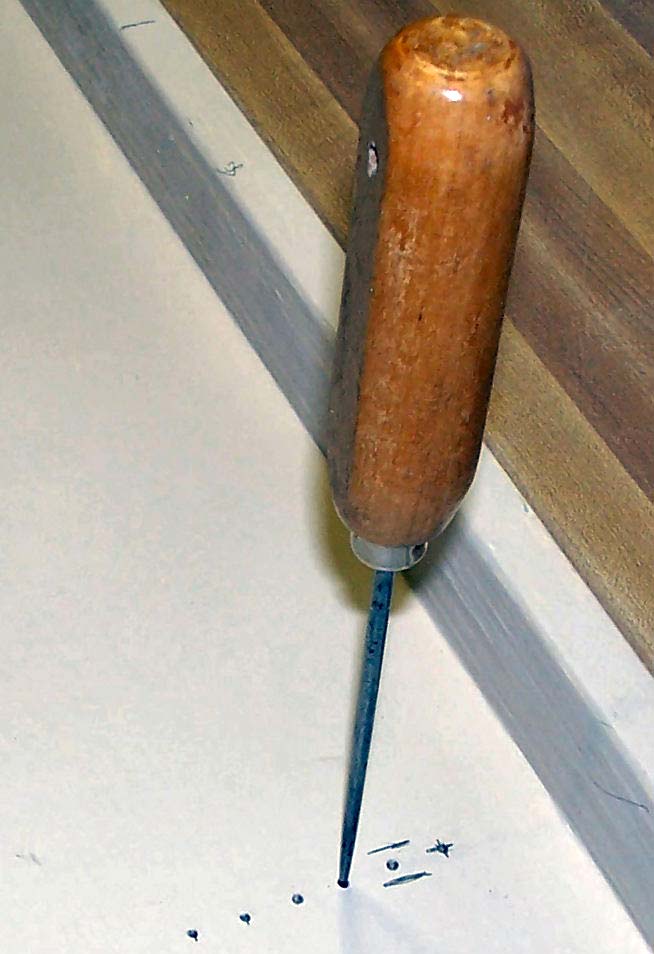
Figure 20 - Layout for cutting the channel for the power cord.
Note the ice pick that is used to make pilot holes at each hole. You must not drill completely through the shelf, which is only 3/4 of an inch thick. After the holes were drilled, the groove was carved out first using a wood chisel as shown in Figure 21 and then files.
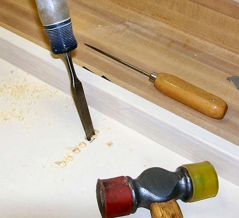
Figure 21 - Cutting the power cord channel first with a wood chisel, then using files.
It takes a little work, but the light cord fits nicely into the groove shown in Figure 22, and it can curve around at 90 degrees as you can see in Figure 23.
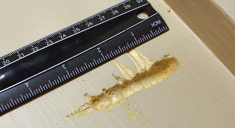
Figure 22 - The cut channel for the power cord.
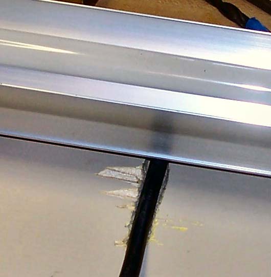
Figure 23 - Fitting the power cord into the channel.
The back of the light fixture fits nicely against the bottom of the shelf. The instrument shelf is completed by painting both sides. The bottom was painted first to avoid problems with not fully cured paint sticking to the newspaper used to protect against paint drippings. I wanted the light reflected off the bottom, so I painted it with semi-gloss white latex paint using a brush (Figure 24).
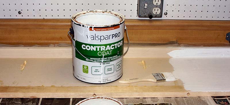
Figure 24 - Painting the shelf’s bottom with white paint.
The white dried with streaks showing through, so this called for two coats. I turned the shelf over and painted the top with a light beige latex paint again using a paint brush (Figure 25), which covers with just one coat.
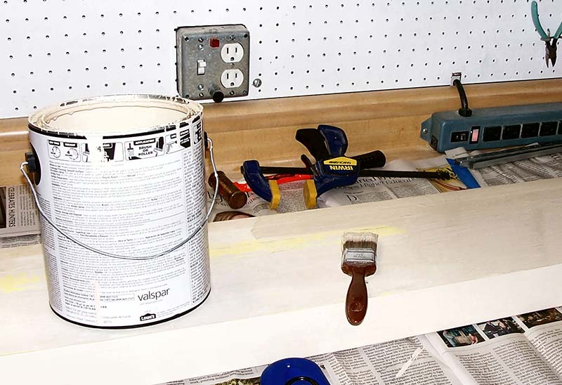
Figure 25 - Top of shelf painted with beige latex paint.
I found both paints off the ‘return shelf’ at Lowe’s for just $9 a gallon. It was just a matter of starting early in the project and checking what paints were there each time I went to the store. Beige paints are the most common to find; the white took a fair amount of time to find, but persistence paid off.
The Lights for Your Work Area
Once the paint was thoroughly dried, it was time to install the two LED lights which the instrument shelf was prepared for. The LED lights come with two studs on their tops — one at each end of the light. The hanging stud has a small hole through its side where a hook can be inserted to connect to a chain, so the fixture can hang from the ceiling.
This hole is large enough for a 4-40 machine screw to pass through, so I designed a simple hanger that attaches to the stud with a screw that forms a ‘dog ear’ extending past the fixture’s end, so a screw can hold the light in place.
A drawing of this hanger is shown in Figure 26 and it’s simple and quick to fabricate.
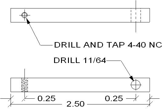
Figure 26 - Mechanical drawing of the dog ear used to hang the light from the shelf.
It’s made of 1/4 inch square aluminum stock with a 4-40 thread tapped on one side. Then, at the opposite end and side, is a thru hole for a #8 sheet metal screw. The hanger is first installed on the light using a 1/2 inch 4-40 hex socket screw through the stud hole into the hanger’s side. Figure 27 shows the opposite end is positioned to stick out from the end of the light fixture.
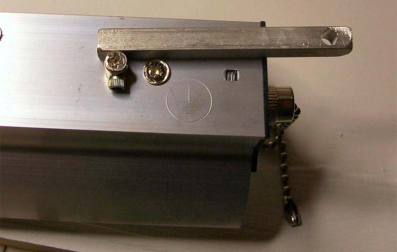
Figure 27 - Installing the hanger onto the LED light with a 4-40 socket screw sideways.
Note the hole at the free end, where the screw that holds the fixture to the shelf will pass through. This is shown in Figure 28, with the ends of both light fixtures.
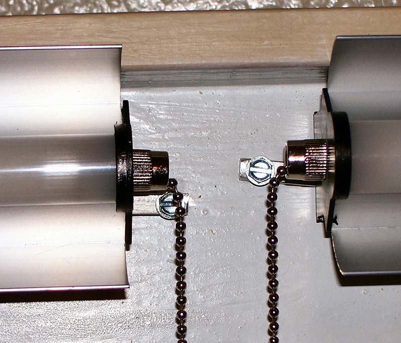
Figure 28 - Installing the LED lights under the shelf using the light hangers.
Looking carefully, you can see a screw through the hanger into the wood backing of the shelf’s bottom. The lights are butted up against the overhang of the front of the shelf. The same is done to the other end of the light, so the light fixtures are held firmly up against the shelf bottom.
Finally, the power cords coming out via the grooves are routed to the back side of the shelf (Figure 29), then each is secured to the shelf using nylon cable clamps and wood screws, so they are held firmly against the shelf.
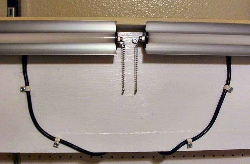
Figure 29 - Final installation of LED lights showing the routing of their power cords.
Now the shelf can be lifted onto the shelf brackets with the two cords threaded down behind the pegboard, then rotated so the upside is upwards and fit into place. The two power cords plug into the duplexes underneath the bench. Now you’re ready to start putting your instruments on it.
A Bench Mounted Lighted Magnifying Glass
One thing that I’ve found very useful in my lab is a lighted magnifying glass — especially as time marches on and my eyes don’t work as well. For my old bench, I made a bracket from a 2 x 1/4 inch angle iron screwed into the wood of the bench, that held the clamp for the light to slip over. The screw clamp was tightened as tightly as possible. Unfortunately, as the light was moved about in use, the clamp would loosen and slip.
To get around this problem, I decided to make a holding platform with a steel pin through the light’s holding base, so it couldn’t move regardless of how tight its screw clamp was. Also, any base would need to step down and pass under the leading edge of the countertop. Looking at Figure 30, you can see the completed holder base already attached to the bench frame, extending out from one of the table supports with the step-down being apparent. Note the holding pin on top.
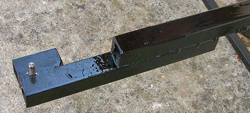
Figure 30 - Light holding base support built out from the bench frame.
Made with the same one inch 062 square steel tubing used to make the bench frame, you can see where a short length of tubing is welded on the side of the extension to form a flat platform for the light’s holding base.
The steel pin in the center was made from some 1/4 inch steel round stock, then drilled a quarter inch hole through the top of the light’s holding base. The holder was then installed on the platform where I wanted it, then I drilled a quarter inch hole through the holder’s hole, then another through the steel tubing. It was then just a matter of inserting the steel pin through the tubing and welding it at the bottom. The holder slips onto the pin as shown in Figure 31 and the screw clamp is adjusted to press on the bottom of the platform, holding the light fixture snugly in place no matter how much it’s moved about.
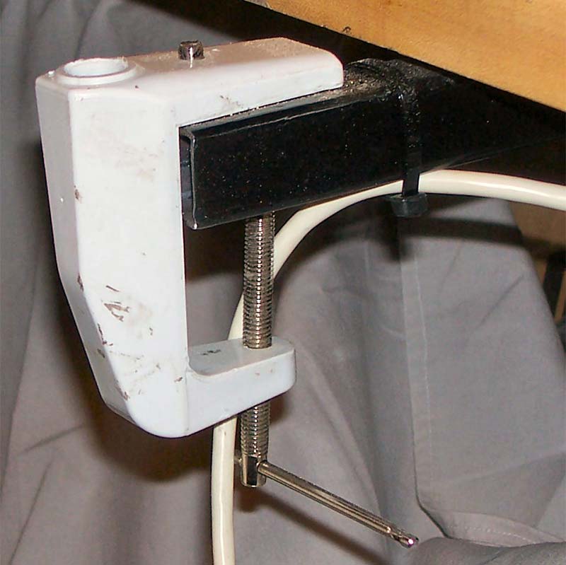
Figure 31 - Light swivel base installed on the bench holding base.
Figure 32 shows the light’s pivot pin by the socket of the base, which the pivot pin will insert into.
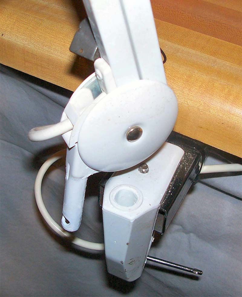
Figure 32 - The pivot pin of the light seen to the left of the socket of the base, prior to installing.
Looking at Figure 33 you can see how it’s mounted, making it useable over most of the bench and able to pivot either direction to either side of the bench. Note the photo insert in the middle of Figure 33 showing its pivot pin now inserted in the socket of the base.
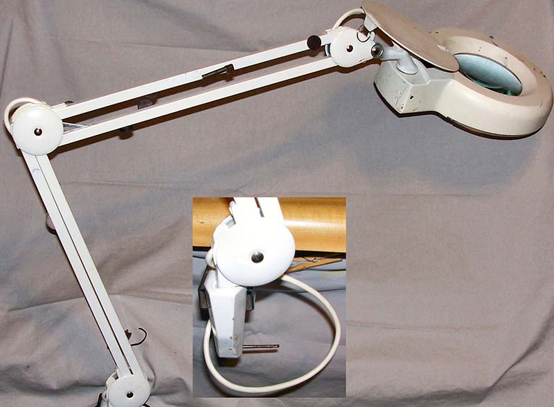
Figure 33 - The magnifying light installed and ready for use.
I hope you’re enjoying this project so far, but this is just the halfway point. There’s more to come in the next issue, when we continue with our workbench design ideas. SV
Article Comments