Designing a New Workbench for Your Robotics Hobby
By James Lyman View In Digital Edition
After a twenty-year hiatus in electronics, retirement has provided the time to return to the arts of the electrons, and therefore created the need for a new bench.
I graduated as an Aerospace engineer in the spring of 1972 in the middle of the collapse of the aerospace industry and, with a low draft number, it was off to the Army. Having always experimented in electronics and with the electronics industry booming, I decided to pursue an electronics engineering career.
I would have my GI bill education benefits, but still would need to work to make ends meet. So, I elected to take the electronics technology correspondence course offered by Cleveland Institute of Electronics to reinforce my AE degree, and more importantly, gain an FCC radiotelephone first class license. At that time, every television and radio station required a first phone licensee present when the transmitter was on, so good paying jobs were plentiful.
Instead of taking CIE’s electronic lab course, I elected to buy my own electronic instruments and do my own lab course with experiments. So, I began the correspondence course and with a loan from the credit union, purchased a Heathkit TVOM, a 50 volt variable power supply, audio signal generator, transistor tester, and three inch recurrent oscilloscope. At the same time, I also started my graduate studies in systems management from USC. Needless to say, I was a very busy little beaver, but made good steady progress.
In the next year and a half, I purchased other Heathkit instruments, so my last year in the Army, I decided I needed something more than a small kitchen table for a lab bench. Using a Black and Decker single speed electric drill and saber saw (each costing just $10), I began construction of a custom laboratory bench.
I designed a modular bench so it could be broken down and moved. The back was a series of trusts, spaced a foot apart, each about 10 inches high, with a sheet of pegboard glued and nailed onto the trust face. This way, deep instruments such as my oscilloscope would have a hole cut in the pegboard to set back to be even with the other instruments.
The benchtop was constructed as a ‘wing’ with trust ribs between each drawer, a stressed skin top of quarter inch plywood complete with stringers. I designed it for a quarter inch deflection with a pound center load. Each end had a set of detachable legs.
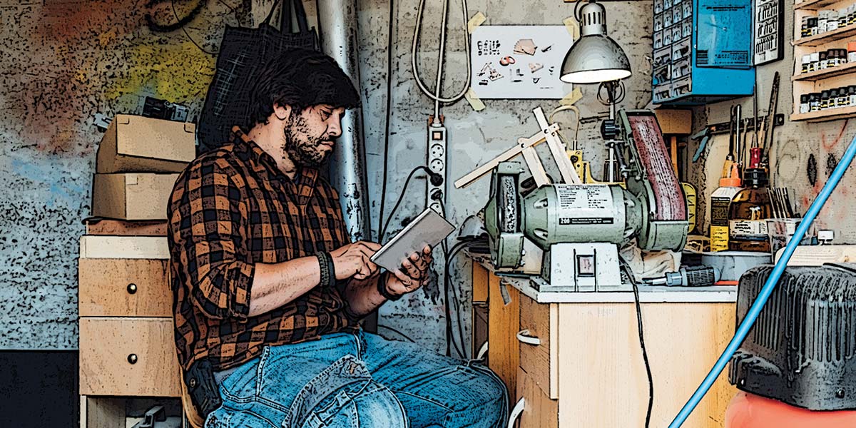
I completed my bench just before leaving the Army in the spring of 1975, and it has served me without fail ever since … until I moved to my present residence, when I decided it was time for something new. Figure 1 is a snapshot of my old bench after years of adding instruments, but little changed since I first built it more than 35 years ago.
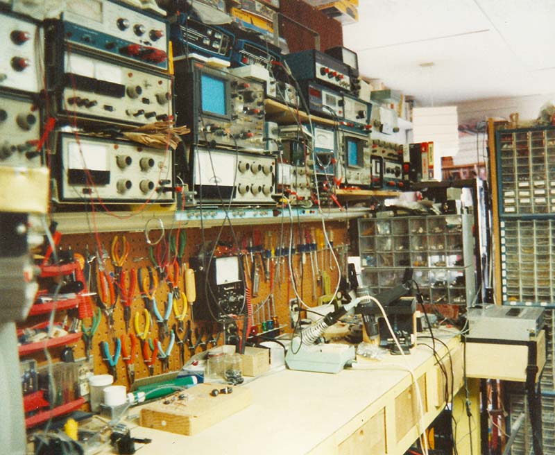
Figure 1 - My original electronic lab bench showing instruments, pegboard for holding tools, and Formica bench top, which I used for almost 40 years.
Since then, I finished my graduate work and my correspondence course and got my first phone, then returned to university to get another degree in electronics engineering. Over the years, I have continued to experiment and learn more about electronic technology, while first working for various companies, then as a consulting engineer using the lab you see here for my design work.
Since 2000, I had drifted away from electronic design and for the last 10 years hadn’t done anything in my lab. Now retired, I’m ready to ‘get back in the saddle’ again, but now only do things I’m interested in … things that I’ve been wanting to do for many years, but just didn’t have the time.
As I prepared to move, my thoughts were on what I wanted for a new lab; in particular, just what I wanted for a new lab bench. For starters, I didn’t want the standup type bench I used for years because standing for long periods is now quite uncomfortable. The new room would be a combination of laboratory and office, so a bench would be defined in large part by the floor plan. A new bench would sit adjacent to my desk to form an ‘L,’ so it would need to be the same height.
The old bench had the foot wide truss in the back, plus about a two foot wide walkway between the wall to allow access to plug sockets, etc. That would eat up too much floor space, so I wanted the bench backed up against the wall. However, this created the problem of no backspace for long instruments such as an oscilloscope, which means those instruments would stick out about a foot from the others. More on my solution later.
One thing about designing and building custom electronic instruments is I’ve built up a surprisingly good machine shop, including welding equipment. Electric wire welding machines are surprisingly cheap and easy to use. Harbor Freight Tools sells a welding machine for around $140 that runs on a 120 volt/20 amp circuit and can weld up to 3/16 inch steel. Such a tool opens up many avenues for building and repairing things, so many that it’s hard to understand why every home shop doesn’t have one.
This is particularly true for those involved in robotics. Indeed, I’ve seen several home improvement TV shows where such welders are used. Over the years, I’ve done several construction projects using 1” x 0.062” thick square steel tubing. It’s easy to work with, cut, and weld to make strong useful structures.
So, instead of the wooden trust structure of before, I would build a bench back that was only one inch wide, yet able to support the weight of test instruments and shelves. For an additional $50, Harbor Freight also has a six inch abrasive chop or cutoff saw that allows you to make precision cuts of steel stock up to one inch thick.
The first steps are having a plan, a drawing of the bench with precise dimensions, and a computer drafting or CAD program to use which is ideal for this. To get good results, again, you need to make careful measurements and cuts.
Looking at Figure 2, you see the basic back frame drawing of one inch square steel tubing with reference designators (the numbers in circles) that show which part is placed where for welding and their position in inches.
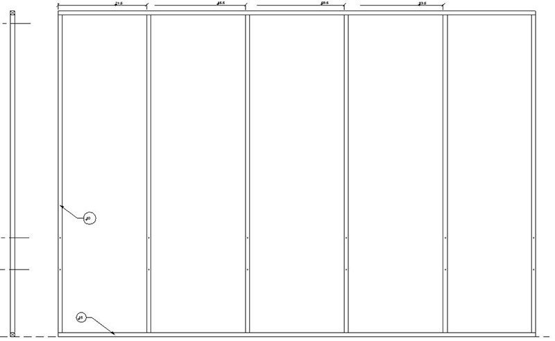
Figure 2 - The layout drawing for the back support structure showing where the steel tubing parts are positioned for welding.
Using a CAD program, you can measure to an accuracy of more than 1/1000 of an inch; more accurate than you can cut them. It’s important to have accurate measurements if the final structure is going to fit and be square, and a CAD program gives you far greater accuracy than you can ever obtain with traditional paper and drafting.
To make cutting materials easier, you can create detailed drawings of parts and subassemblies. Figure 3 has the various parts with dimension details such as where holes need to be drilled, while Figure 4 is a close-up of the Cutting and Drill Schedules.
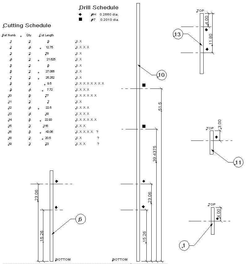
Figure 3 - Detailed drawing of various parts including the Cutting and Drill schedules. Using these schedules makes cutting the various parts and drilling the required holes simpler.
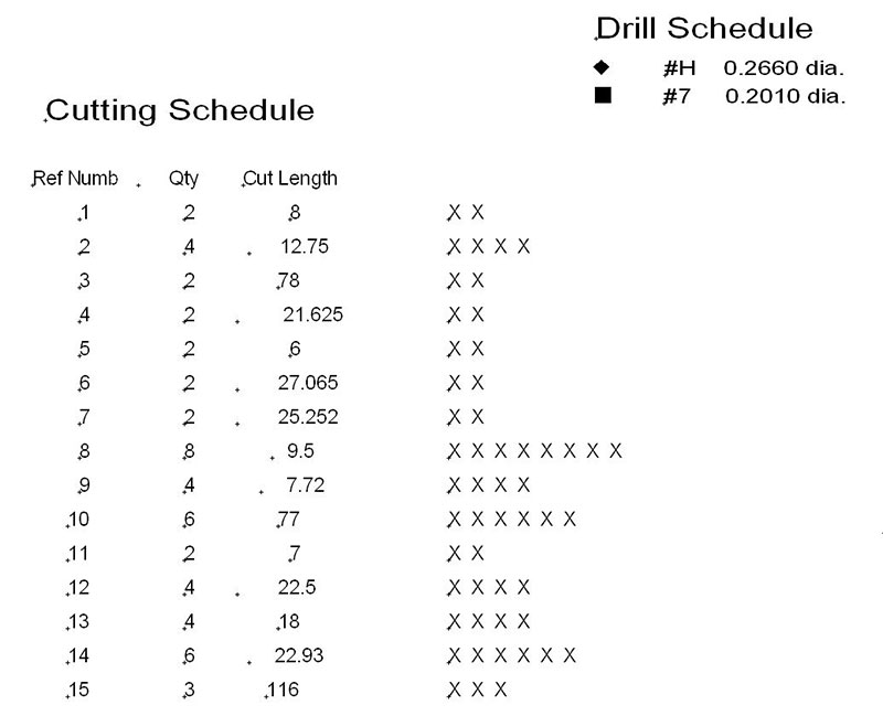
Figure 4 - The Cutting and Drill schedules that allow you to easily manage the cutting of tubing and drilling of holes.
Note the series of Xs on the right side of the cutting schedule; it shows one X for each tube length that must be cut, which is the number under the Qty column. This allows you to keep track of the number you’ve cut by simply marking out each X as you cut one. The length to cut is under the Cut Length column. Finally, on the left is the reference designators under the Ref Numb column.
To use this, you only have to measure the required length to cut, then mark off the X to show the part has been cut. To minimize waste, you start with the longest piece and cut it, then measure the next longest needed piece that will fit in the remaining tubing. With each shorter length, find a part length that will fit. That’s why it’s important to mark off the count Xs so you don’t get lost and cut extra pieces you don’t need.
The holes to be drilled are indicated by a symbol such as a diamond or square to simplify the drawing. The actual drill bit size is shown in the Drill Schedule, so beside the drill symbol is both the drill size (wire gauge) and the decimal size. While this may seem like a lot of extra work, the extra time you spend on your CAD system will help avoid trouble and mistakes later on. Since some of the parts/assemblies must bolt together, great care needs to be taken in measuring the position for drilling as well as where the measurements are made from, so the holes all line up correctly.
Again, using a CAD system for drafting helps you accomplish this.
Drilling the holes accurately is a challenge because you’re trying to hold accuracies to the 10 thousands of an inch range. Even using a drill press as seen in Figure 5, it’s hard holding to such tight accuracies.
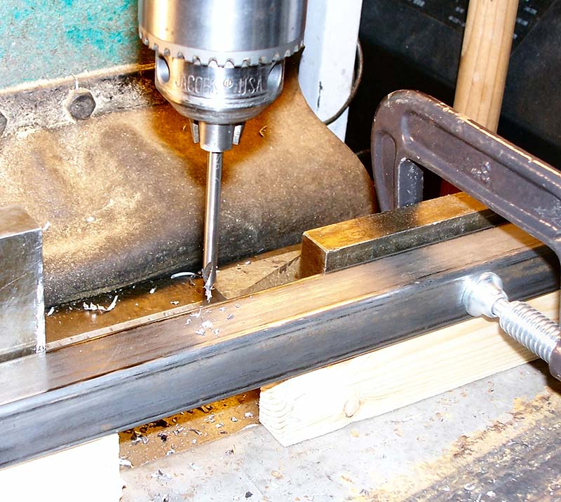
Figure 5 - Using a drill press makes drilling the holes accurately much easier, but if you don’t have one you can drill the first part, then use it as a drill fixture by clamping the parts together.
To hand drill, you’ll need to drill one tube, then use it as a drill guide for the rest by using quarter inch spacers and C-clamps. The bit shown in Figure 5 is called a centering bit and has a thick shank with a small drill point at the end and a counter sink.
This allows you to drill a small hole then a countersink without the drill bit skating on the surface as the drill bit flexes. You can then change to the actual drill bit; the countersink hole holds the bit steady in place as it bites into the metal to drill exactly where it’s supposed to.
Looking at Figure 6, you can see the various cut tubing parts, ready for assembly.
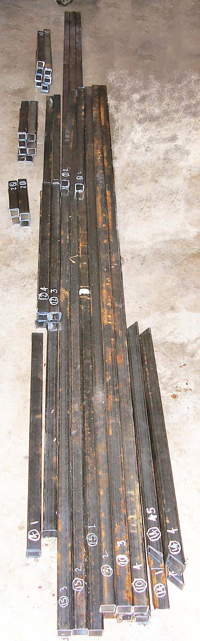
Figure 6 - The steel tube cut and labeled for parts to be assembled.
Note the white numbers on many of the pieces; those in a circle are the reference designators of the part and the other number is the count. These are made with a white paint pen from a hobby shop. This makes identification of parts easier, and the count numbers make it easy to ‘inventory’ parts. The light rust is removed using sandpaper and a wire brush wheel with an electric drill.
Now that the various pieces are cut, the welding can start. The first part is the back frame of Figure 2. This is when your drawings become important if you want to avoid a mess. Refer back to your drawings more than once, and before you start welding, compare your drawings with the pieces laid out ready to weld together — in particular, check which part butts into another.
For instance, note the end side rail fits between the upper and lower horizontal tubes. So, if you have one rail against the horizontal end, the structure will be way out of square resulting in all sorts of problems. It’s surprisingly easy to mis-position a part before welding. It’s much easier to double and triple check the drawing rather than cutting the tubing apart and starting over!
One problem with welding is that the extreme heating of the metal parts at weld joints causes the steel to expand, and therefore the structure bends, twists, and distorts from uneven heating and cooling. The counter to this is called tack welding, where each joint is first welded with a small ‘dot’ or tack until all the joints are tacked together. These small spots of welds don’t heat the material up and therefore it doesn’t tend to distort.
With all the joints tack welded, you can then fully weld the joints, the tack welds holding the structure in place as it heats and cools, thereby remaining square.
C-clamps can be used to hold a structure together while being welded, but still if a joint is welded without first tacking it together, the force from thermal expansion can be great enough to pull parts out from the C-clamp. This problem is minimized when you have interconnections such as the angle bracket seen in the table support of Figure 7.
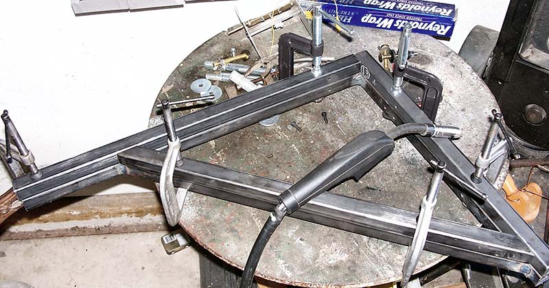
Figure 7 - One completed table support (bottom) used as a holding fixture to weld the next table support, ensuring they’re exactly the same size and shape.
With such support, the expansions/contractions are held in check. Nevertheless, you still tack weld the joints first, then weld the joints. My bench design uses four of these table supports, and you’ll notice in Figure 7 there are two of these table supports, one on top of another.
I made the first bracket, then used it as a holding fixture for each of the remaining supports, thus ensuring all are exactly the same by clamping the pieces to the completed support before tack welding. Note the blue box of aluminum foil in the upper right corner. If you’re welding close to tools such as C-clamps, you can fold the foil over double, then loosely wrap the tool with the foil.
Small splatters of molten steel droplets land on the foil and often burn through it, but in doing so, they cool and solidify, thus not sticking to the tool. You simply pull the foil off, crumple it up, and throw it away.
Despite my best efforts, some assemblies still warped from the heat and were not square. Looking at Figure 8, you see the end support has two lengths of tubing extending out which had to be parallel, but were off by about half an inch.
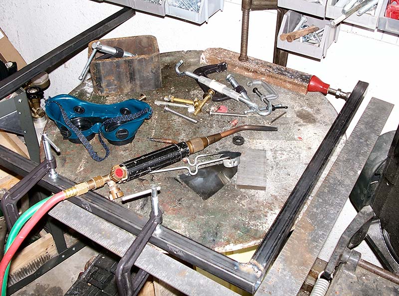
Figure 8 - Correcting the warping from welding by first spreading the parallel tubes and clamping them down, then heating their bases red hot.
I had two choices: 1) Cut the tubes apart and start again; or 2) Use a screw jack to spread the tubes, then heat their bases red hot to set the position.
Note the small red machinist’ss screw jack (about $5) in the upper right corner. With a block of steel secured with a C-clamp and the connecting piece secured with C-clamps, the screw jack is extended, forcing the tubing outward until the two pieces are square.
I have an oxy-acetylene torch and therefore the heating of steel red hot is quick and easy, taking just a minute or two. You could probably use a propane torch, but it will take longer.
Once I heated it all around, I let it cool down completely. When the C-clamps were removed, the member remained in its position. I repeated the process with the other extended members, making the assembly square.
Looking back, I should have added corner cross angles: a square tubing that sets at 45° like the table supports. This would have prevented the warping like it did with the table support. I’ll know better next time!
The back frame is used as a holding fixture for the end frame as shown in Figure 9, where the back frame is shown in red, the end frame is black, and the cross section of the countertop in green.
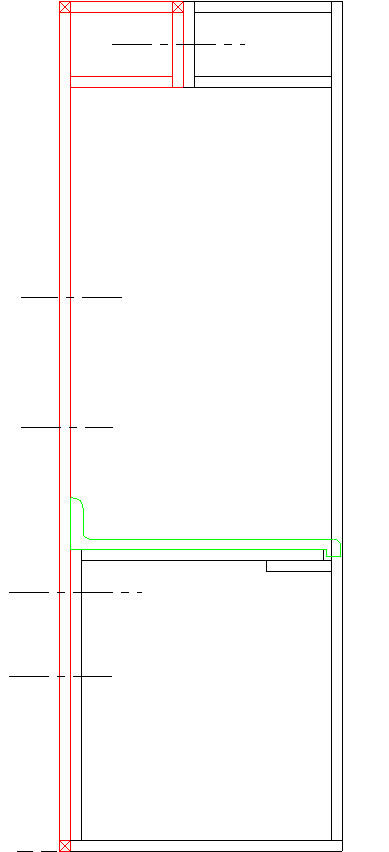
Figure 9 - The end frame (black) bolted to the back frame (red), with the countertop (green) in place.
Figure 10 shows the corner where the small U assembly will be installed. The center lines show the position of the bolts (1/4 - 20, NC); two on the bottom and one at the top.
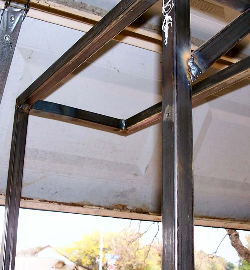
Figure 10 - The end of the back frame where construction of the end frame starts with the top portion of the back frame, in the center of the figure.
To start, the small U and L parts are bolted together with a single bolt since they’ll fit together in the final frame, as in Figure 11.
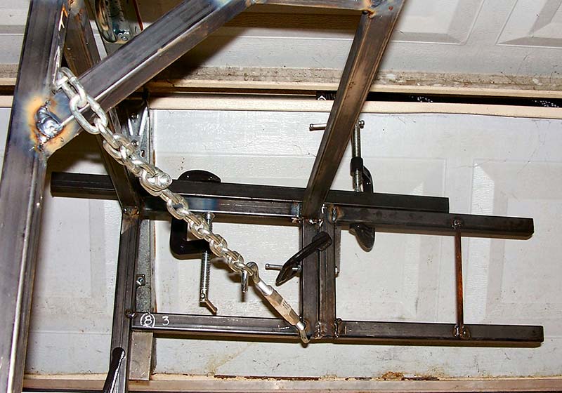
Figure 11 - The two parts of the end top are bolted together, then using a piece of tubing across the frame top, those parts are clamped to the tubing to be held in the correct position for welding.
Note the square tube (clamped on top) used to hold and align the L and U parts on the frame for welding. No matter how hard you try, things will not come together square and equal, so now you must use C-clamps, screw jacks, and turn buckles with chains to bend things into correct alignment, as in Figure 8.
Once the assembly is in position, each joint is tack welded to hold it in place. The chain and turn buckle are used to pull the assembly into square with the rest of the frame. Note the steel block on the lower left edge of the picture, setting behind the steel tubing to form an edge that holds the other tube in place. Using a C-clamp, the assembly is twisted into position prior to tack welding.
The U frame from Figure 8 is then bolted to the lower part of the back frame, and these two upper and lower assemblies form the bases for positioning the vertical steel tube. Now, the vertical tube is set against the ends of the small U (top) and the large U (bottom), then tack welded in place. Note there’s a short length of tubing under the upper member of the large U assembly that allows the lip of the countertop to step down. This is the last part added before joints are tack welded to hold everything square and in place, then the welding of the structure is completed.
Looking at Figure 12, we see the completed end frame: tack welded together and ready for final welding (with the heat-treated members in tension to ensure it is square).
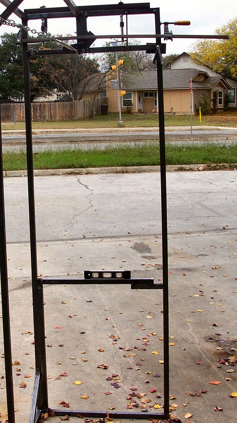
Figure 12 - The completed end frame, welded together and ready for final welding prior to being removed.
The clamps can now be removed, then the three bolts (one upper, two lower) are removed, so the end frame easily comes off the back frame.
In Figure 13, the end frame is placed on sawhorses so the welding can be completed.
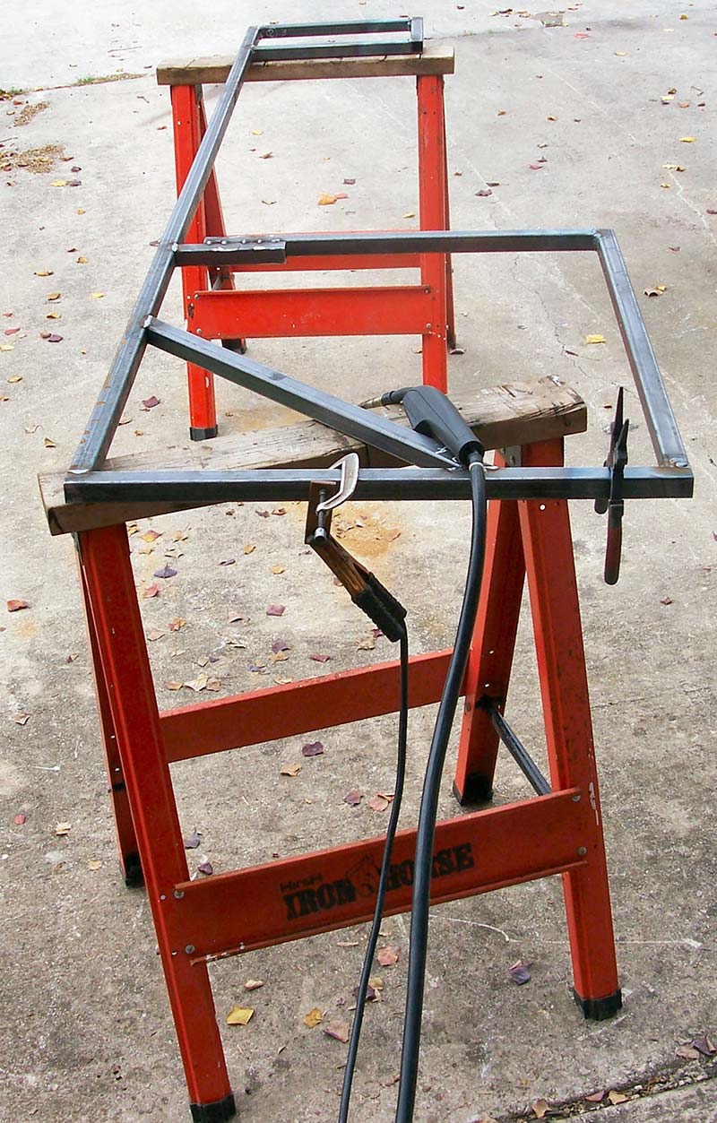
Figure 13 - The end frame removed from the back frame and set on sawhorses for the final welding to complete the end frame, and therefore the steel frame for the bench.
Once done, the end frame can be reattached to the back frame with just those three bolts. Despite the spindly appearance of the structure, it’s actually quite strong and rigid once fully assembled and the countertop is installed.
Using steel tubing and welding does present some challenges. You can do the same thing working with wood; it just won’t be as rigid and substantial as using steel. Buying a low-end welder just to build your dream electronics bench is a bit questionable since a welder opens all sorts of doors to you. I also built a home entertainment center using the same steel tubing and my welder as seen in Figure 14.
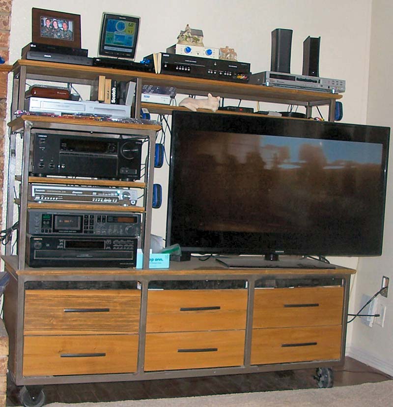
Figure 14 - My home entertainment center also used steel tubing welded together to give a frame resistance to flexing and breaking loose when moved.
It has large casters mounted under it that allow me to easily pull it away from the wall to get behind to plug wires and power in without having to stand on my head. Rolling it puts stress on the structure, so a wooden frame would quickly loosen and pull apart.
(On my ‘to do’ list is to build a television cart on castors for the bedroom which will house a small refrigerator below the television.)
By now, you should be able to see the value of CAD drawings in building complex structures — especially getting bolt holes to align. In engineering, we have the P6 law (pronounced P to the sixth): Pre Planning Prevents Piss Poor Performance! Using a CAD drafting system allows you to avoid violating that law.
Once all the welding is done, the pieces are bolted together to form the complete support frame shown in Figure 15.
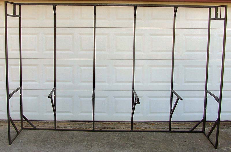
Figure 15 - The completed frame for the bench where the countertop will rest, and mounting shelf brackets for shelves to hold the instruments at eye height.
The countertop rests on the four horizontal triangle supports and the two cross members on the ends. Looking at the side view of the frame in Figure 16, you can better see the support structure for the countertop laying across the six horizontal members.
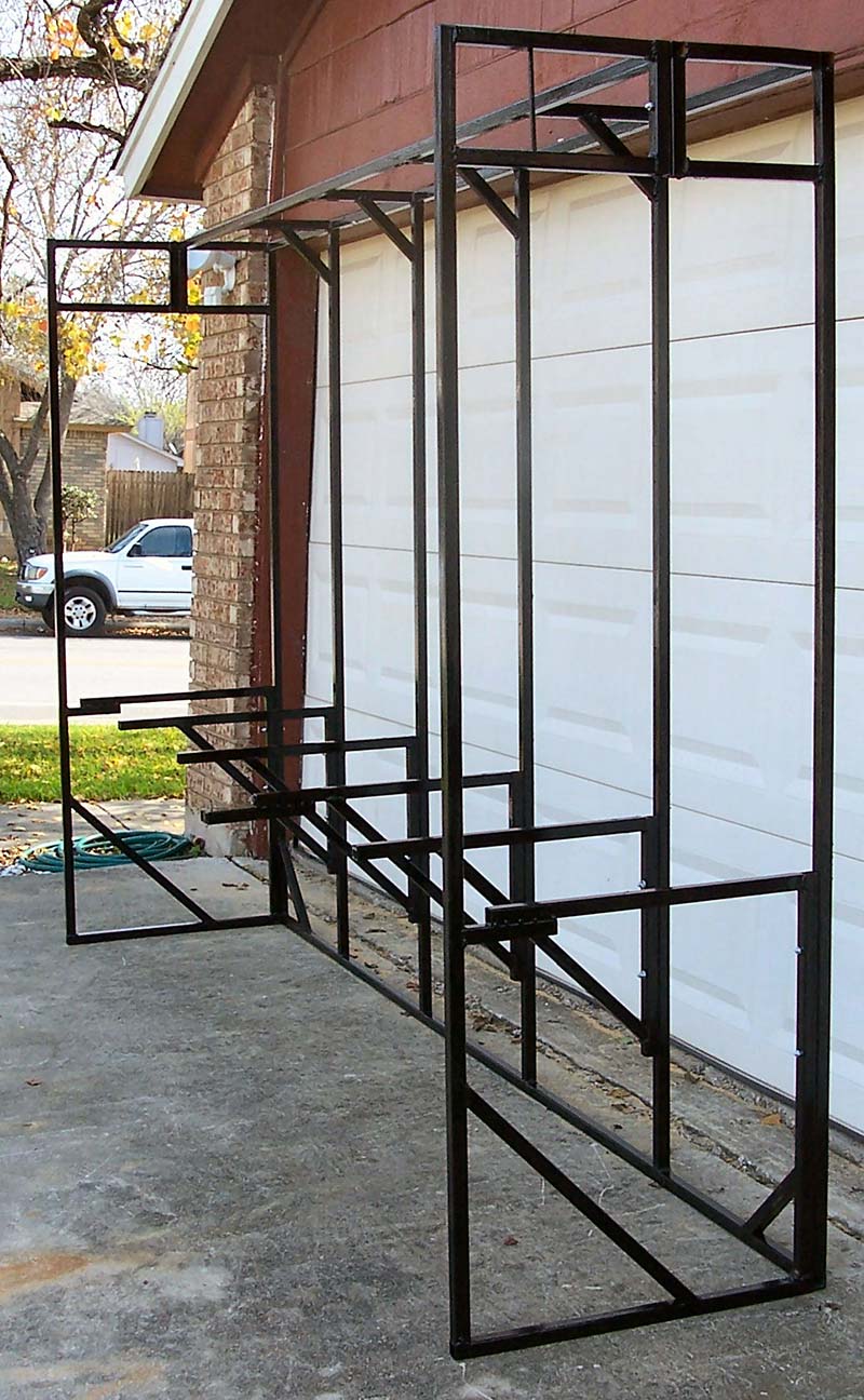
Figure 16 - View from the end better shows the makeup of the support frame. Note the several angle members in corners to make the structure more ridged.
Looking at the top, you can see the two parallel rails that are used to support a shelf, while the two end frames support all the weight hanging on the back frame. This way, the whole thing doesn’t tip over. Also note the angle cross supports to give support members more rigidity against bending. A little extra steel tubing and welding can go a long way in strengthening a structure.
With the frame completed, the next step is providing the electricity for all those instruments to plug into. My old bench had a master cutoff switch that turned off all the power to everything — the bench lights, instruments, soldering iron, drills, etc. — thus preventing accidently burning the house down by forgetting to turn the soldering iron off. Over the years, I did forget to turn that hot iron off a few times, but my master cutoff switch protected me, so it’s a ‘must have’ feature of my new electronics bench.
To keep the power cords out of the way as well as out of sight, I wanted to drop the electric cords down the back to plug in under the bench. That meant having some wood backing that electrical utility boxes could be mounted on.
I was able to salvage all the electric parts from my old bench: 15 duplex sockets, 10 gang boxes, the switch, and cover plate with a pilot light and fuse. I used an eight foot long 1x4 pine board to mount all the boxes on. The board hangs under the horizontal member of the four table supports using screws. Now, the real fun starts: wiring all those duplex sockets together.
This is made more challenging because the duplex sockets I salvaged were over 50 years old and didn’t have the ‘plug in the wires’ feature, so each connection had to be made with the screw terminals. A tedious, time-consuming process that grows old very quickly.
There are 14 duplex sockets having a total of 70 screw terminals! I used individual stranded AWG #14 wire, standard black and white, and bare solid AWG #16 wire for the ground. The rule for house wiring is simple: ‘black to gold and white to silver.’ The duplexes are colored coded with black wires (called line) connecting to the gold color (actually brass) terminals, and the white wires (called common) connecting to the silver color, with a green terminal used for the ground connection.
Crimp-on spade lugs are used to make connections to the screw terminals on the duplexes easier. The tools used to do that are shown in Figure 17.
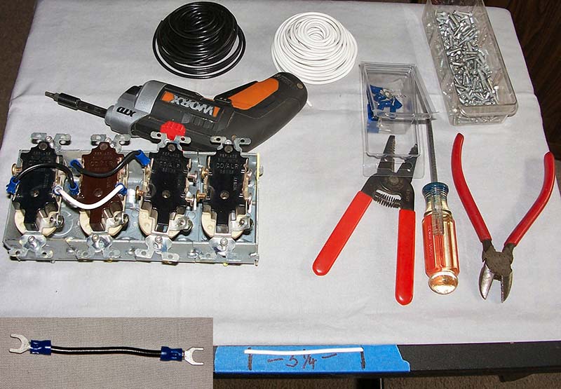
Figure 17 - The tools used to crimp spade lugs on the wires for wiring duplexes. The completed wire is shown in the inset (lower left corner).
To make cutting the wires easier, a piece of masking tape is placed on the worktable, then the length of 3-1/4 inches marked off as seen on the lower middle portion of Figure 17. The inset on the lower left corner shows a wire with two spade lugs crimped on, ready to install on the duplex.
To make the wiring of duplexes easier I needed some kind of a holding fixture, which holds all the duplexes in line and together at the correct spacing for going into the utility boxes (Figure 18).
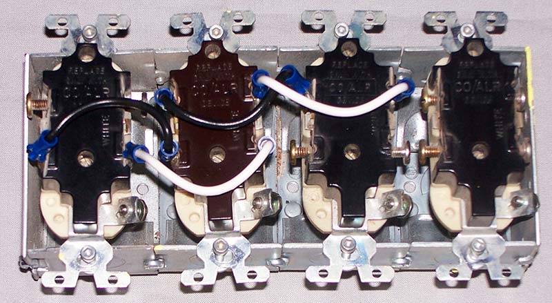
Figure 18 - Using ganged utility boxes as a holding fixture to wire the duplex sockets in parallel. Once all the wiring is done, simply take out the screws and flip the sockets over, then reinstall the screws.
The easiest fixture was the ganged utility boxes themselves which the duplexes were going in. To do this, I set the duplexes upside down on the box, then put screws in to hold them in place. I had a bunch of 8-32 hex socket screws, so I used them which makes it easier to use an electric screwdriver to install, remove, and loosen the screws thereby exposing the duplex screw terminals.
Before installing each duplex cluster in the ganged utility boxes, it’s a good idea to test the cluster to ensure it’s wired correctly and there aren’t any shorts. First, test for shorts using a DVM or multimeter by testing for continuity (open circuit, so no continuity) between the black, white, and ground connections. This is especially true when using stranded wire where a small sliver of copper can get caught between electrical parts causing a blue flash of fire, a puff of smoke, and a tripped circuit breaker.
A ‘cheater cord’ is made by installing alligator clips on the ends of wires from a salvaged power cord from an electric appliance. Since the tester will need a ground connection, the power cord must be a three-prong cord, so you need three clips. I put a red insulating boot on the hot or line wire, a black on the common wire, and a white on the ground lead.
To test if you’ve truly got the line, common, and ground leads identified correctly, use your DVM to measure the voltage. The ground lead and line will have the 120 volts as well as the common and line, while the ground and common will not.
This means plugging the cheater cord into the power socket in the wall. Therefore, you’re going to be working with exposed electricity that’s strong enough to send you ‘packing.’
So, remember the ‘one hand rule’ for electronics technicians, which is always keep one hand in your pocket when working with high voltage. It only takes one half of one milliamp across your heart to send you to your maker. Touching both hands across a voltage source and ground sends that small amount of electricity right across you heart!
It’s not the voltage that kills, it’s the amperage!
With that note, connect your cheater cord to the bank of duplex sockets as shown in Figure 19, then plug in your AC circuit tester into each socket (two per duplex) before plugging in the power cord.
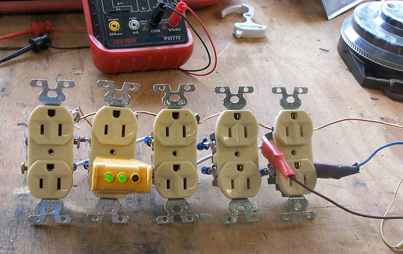
Figure 19 - Testing the duplex cluster for correct wiring prior to installing it in ganged utility boxes using a common AC circuit tester.
Don’t try to plug/unplug the tester (the yellow box with two green lights in Figure 19) when high voltage is present. That’s just asking for a jolt of electricity that hopefully causes nothing more than wet pants!
Start at one end and test each plug one at a time. If the socket is good, then two green lights will light up. If there’s a problem, the lights will be different. Figure 20 shows three testers that I have acquired over the years, and you can see a label on each giving the problems associated with each light pattern.
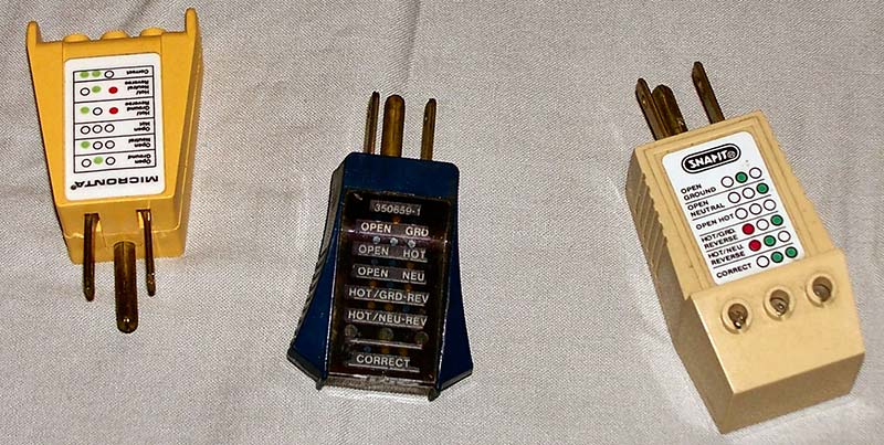
Figure 20 - Several common AC circuit testers found at any building supply or hardware stores that quickly test if duplex sockets are correctly wired, such as if the black and white wires are reversed.
These handy devices cost only $5 to $10 each at any hardware store and are worth the money anytime you’re working with AC power in your house or shop. Those little green and red lights can quickly tell you what your electrical problems are such as the black and white wires being reversed or when you’re correctly wired. Again, make sure you disconnect the AC power when plugging and unplugging the tester.
In testing, I did find one duplex that was incorrect. By using the light codes, I quickly found the problem and corrected it. It’s easier to repair a problem in a duplex cluster before they’re installed, so that’s why it’s important to test each cluster by itself.
With each duplex cluster tested and ready, the next step is to install them in their ganged utility boxes. I used a 1x4 pine board to mount all three ganged boxes using screws. Looking at Figure 21, you can see I used sheet metal screws with their hex heads so it’s easy to use power screwdrivers to install them.
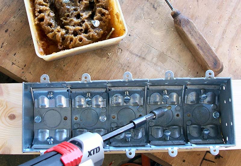
Figure 21 - Installing the ganged utility boxes on a 1x4 wood backing using screws.
I put one #8 x 3/4 inch screw in each box, through the holes in the box’s back, and into the wooden board. This holds the boxes on securely when you’re pulling plugs out.
Note the ice pick in the right upper corner of Figure 21, which is used to make a starter hole, so the screw easily bites into the wood instead of skating around. Also note the funny looking plastic tub of brown mush. This is a plastic storage container used to carry sandwiches, and the brown mush is actually bee’s wax from a toilet ring.
A useful little tip is you can use this bee’s wax to lubricate wood screws so they turn into the wood easier, but hold just as well as an unlubricated screw. I’ve used this trick for years and the rings last almost forever. The wax ring you see in Figure 21 is my second one; I got the first one in the early ‘70s. You can use an old used one if you want, but new toilet rings are so cheap (about $5), why risk the unpleasantries of ‘contamination’ and such?
Looking at Figure 22, you can see the completed electrical distribution system mounted on an eight foot 1x4 pine board, leaning up against the bench frame.
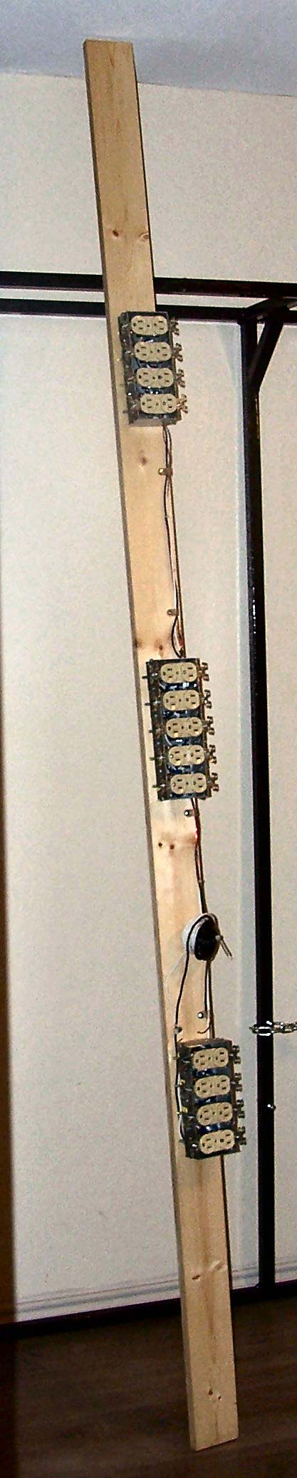
Figure 22 - Completed electrical power distribution system mounted on an eight foot long board.
The duplex clusters are wired together with the same types of wires used to interconnect the duplex sockets, as seen on the right side of the board and in the closeup in Figure 23 which shows greater detail.
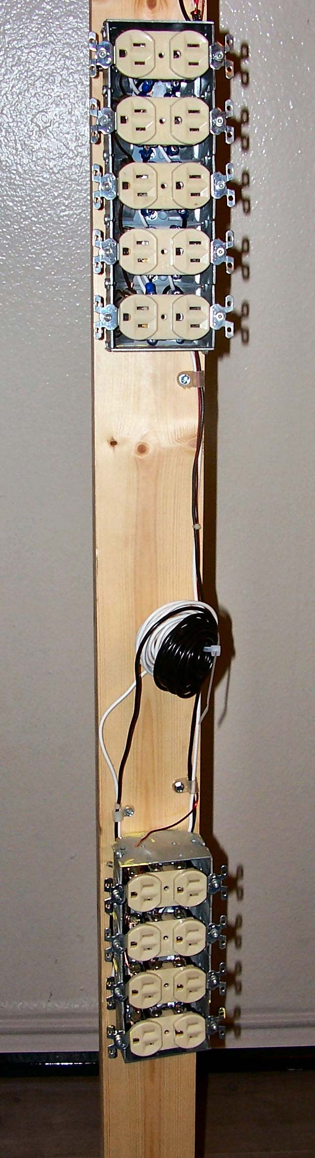
Figure 23 - A close-up of the distribution system showing the duplex clusters in greater detail.
The interconnecting wires are bundled together with nylon tie wraps, then nylon cable clamps are secured with screws to hold the wires down on the board. You can see the coils of black and white wires secured to the board waiting until the installation of the power on/off switch. Notice there’s an extra foot of the board on each end, so if by chance I do run out of sockets, a conventional power strip can be secured on either end and plugged into a socket to give an additional six or so sockets.
With the back frame now in my lab and the power distribution board done, it’s time to assemble the frame structure by bolting the four table supports onto the back frame, but the power distribution board hangs from under these table supports. Because of the limited space (the bench goes from wall to wall), the board must be threaded through the four table supports.
However, the weight of the power board and the individual table supports (plus the close tolerances of the table support holding bolts) makes installation very difficult, so the board must be suspended as each table support is slipped over it.
Only after all four table supports are in place and secured with bolts can the power board be secured in place, hanging under the four table supports as seen in Figure 24.
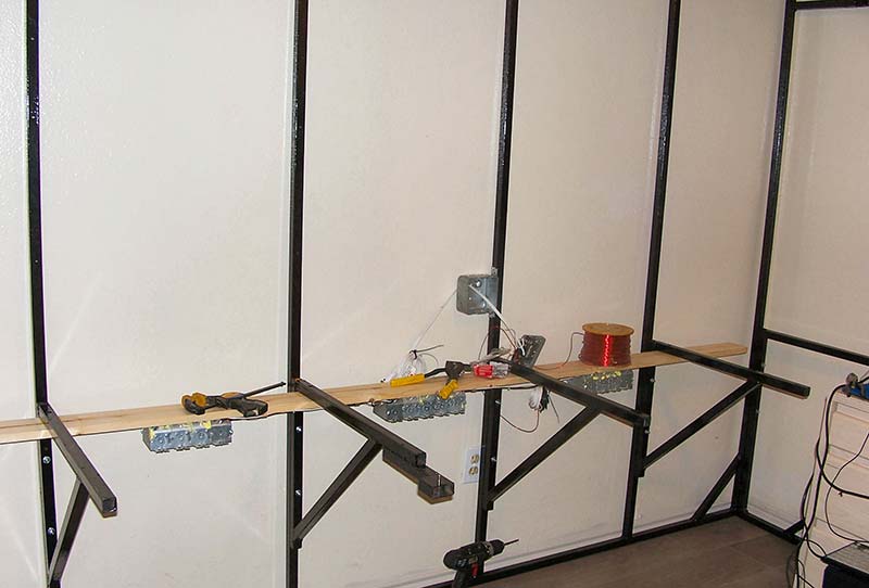
Figure 24 - The completed bench frame in my lab with the power distribution board installed by hanging it under the table.
The board is secured with screws through the steel tubing of the table supports.
The installation of the power on/off box completes the electrical distribution system. Looking at Figure 24, you can see in the center of the picture a junction quad box mounted to the side of the steel upright of the back frame. This box came with a steel bracket spot welded to the side of the box for mounting to a building. This bracket is ideal for mounting the box on the square steel tubing. I chose to use 3/16 inch pop rivets by using a clamp to hold the box in place on the frame, then drilling a 3/16 hole into the tubing.
Figure 25 shows the box secured to the frame and the insert (upper right corner) shows the single pop rivet which holds the bracket tightly to the frame.
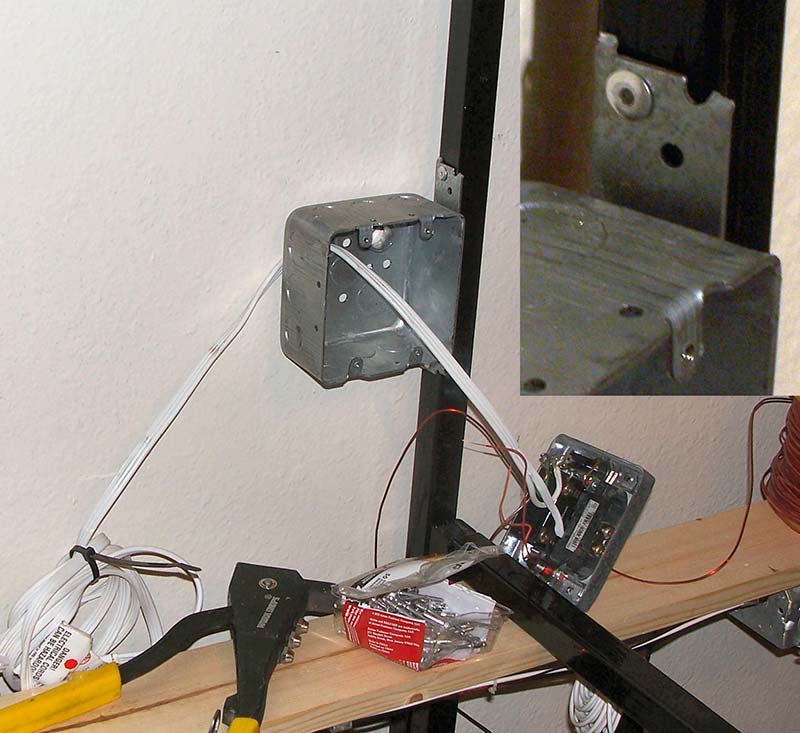
Figure 25 - The switch box mounted on the side of the upright back frame. Insert shows use of a pop rivet through the box bracket to secure it to the frame.
A second rivet is placed on the bottom end of the same bracket. The switch box is positioned between the top of the countertop back board and the bottom of the first shelf. This makes a convenient place for the switch, giving easy access.
The switch in this box is the only switch for turning power on and off to the whole bench. Looking at Figure 26, you see the control box while being tested.
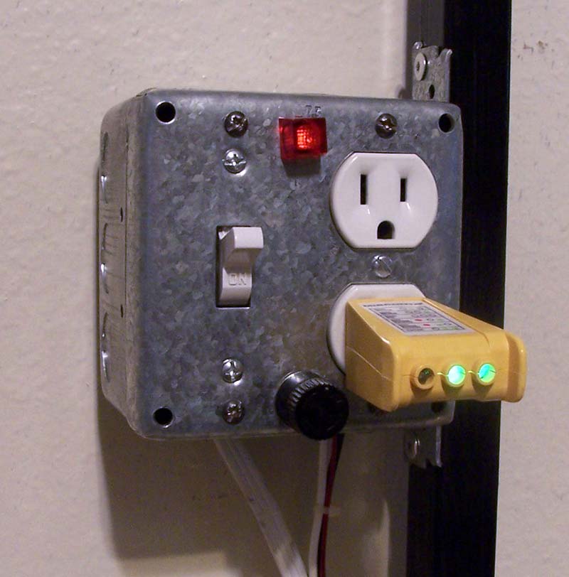
Figure 26 - Power switch box showing the power switch, pilot light, duplex power socket, and the panel fuse holder.
On the left center is the power switch; up for power on, down for power off. Center top is a red pilot light which shows that the power is on, then a duplex socket with an AC circuit tester showing it’s correctly wired.
Finally, there’s a black knob on the bottom center which is a standard panel mount fuse holder with a 15 amp slow blow fuse. The heavy white wire entering from the bottom left is the AC power cord going to the plug. The line side of the cord goes first to the fuse holder. The other side of the fuse holder takes the electricity to one side of the power switch, with the other side of the switch going to the duplex sockets.
The common side of the power cord goes directly to the silver terminal of the duplex socket. The pilot light is wired to the hot (gold) and neutral (silver) terminals to the duplex socket, so it lights up whenever power is applied to the duplex. Looking on the bottom right of the box, you can see the white, black, and bare wires coming out and going to the power distribution board. These wires connect to the end duplex, thus wiring the other duplexes in parallel so when it has power, all the other duplexes have power.
Let’s talk about the bench top, which is what this whole steel frame was built for. Because of size limitations of the room and my desk, the two end frames’ length was fixed, therefore the countertop had to be notched about 3/4 inch, so the countertop could fit the frame. To install, I had to set the countertop up on its backboard, then swing it down so the notches slid around the steel tubing. There was no need to secure the countertop to the frame. This completed the basic bench as shown in Figure 27.
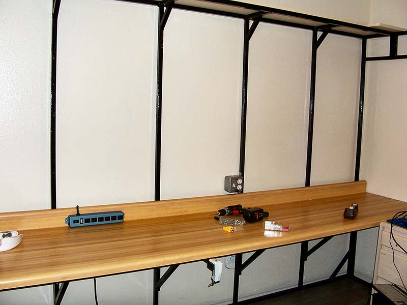
Figure 27 - Completed bench frame with the countertop installed, ready for the next phase of construction.
You can see how the instrument’s power cords will drop down behind the bench to be plugged in.
The next phase of construction is the various accoutrements and accessories such as peg board and shelves for the instruments. As I mentioned, although a bench can be built of wood (see my original one in Figure 1), building with steel gives you a much stronger and compact bench. Considering the low cost for welders and cutters for steel, you should really consider the purchase of a low-end wire welder and six inch abrasive chop saw.
This is particularly true for building and working in robotics or other servo control machines. Besides, once you have the tools, you’ll most likely find other projects and things to repair around the homestead. It’s a good investment you will come to appreciate.
Here’s a little tip about welding: Listen to your welder. When you’re welding correctly, it will sound like bacon frying!
Next time, we get our workbench complete and ready to work on. SV
Article Comments