Designing 3D Printed Bodies for Insect Class Combat Robots
By David Kanoy View In Digital Edition
“They sent a Slamhound on Turner’s trail in New Delhi, slotted it to his pheromones and the color of his hair. It caught up with him on a street called Chandni Chauk and came scrambling for his rented BMW through a forest of bare brown legs and pedicab tires. Its core was a kilogram of recrystallized hexogene and flaked TNT. He didn’t see it coming. The last he saw of India was the pink stucco facade of a place called the Khush-Oil Hotel.”
William Gibson — Count Zero, 1986
3D printing has become many builder’s central material for Insect class combat robots. Team Wait For It started competing in combat events less than two years ago with 3D printed Fairyweight designs and has found a lot of success. We would like to share some of our winning design methodology using our robot called Slamhound as an example of a winning FDM printed design
This robot was designed to comply with SPARC rules for the 150 gram class and also happens to comply with the UK Antweight 4” cube rule. This article assumes basic knowledge of 3D printing techniques, model slicing, and willingness to learn 3D design software. We acknowledge inspiration from great builders, Alex Shakespeare and Chris Bycroft. This design would not be what it is without what we learned from their work.
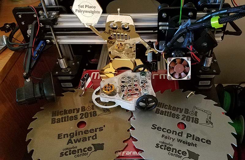
Figure 1. Slamhound assembled bot with trophies.
By now, everyone has seen fused filament 3D prints in many applications, including robotics competitions. A primary requirement for designing parts that work for you is learning all the strengths and weaknesses of the fused plastic material. Very generally, FDM plastic is strong in tension, and can be pliable or rigid depending on the material used, but can be weak in layer separation or compression impact situations.
Everyone has seen plastic confetti sheared off a brittle printed bot. Consider whether you need flexibility to absorb hits, or rigidity to minimize vibration and keep your wheels on the arena floor.
For best results, learn and understand the limitations of FDM printing design. Avoid steep overhangs. Support can be annoying; try to make the print self-supporting whenever possible — especially in tight detailed areas. We use a ton of support to print Slamhound upside down, but we make sure it’s easy to pull out cleanly and doesn’t go into any recesses.
If you print a chassis with a large flat bottom and sides rising off the bed, you may encounter warping. Some filaments can be glued — especially ABS — but most are very difficult to glue or weld in a way that is reliable for combat. We always print a unibody or single print whenever possible.
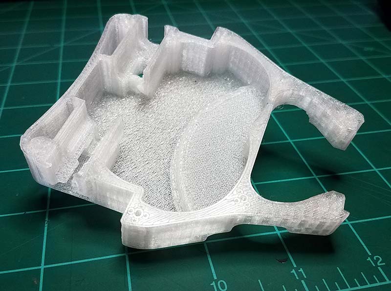
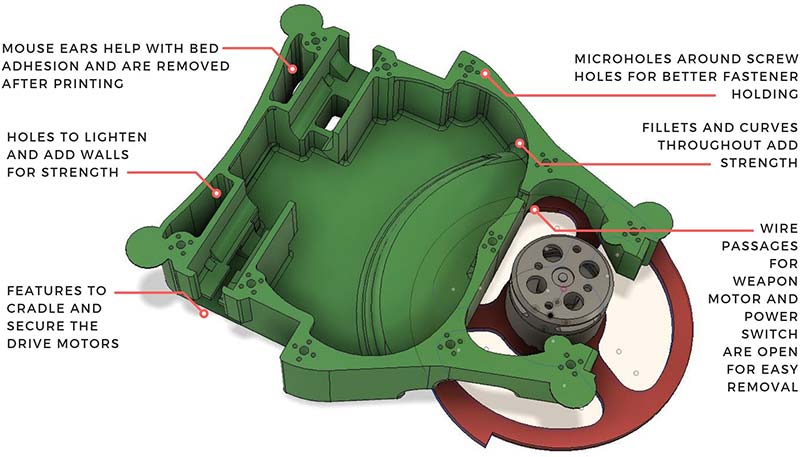
Figure 2. Slamhound isometric with annotations of key features (below), with photo of plain unbuilt chassis at same angle (above).
Depending on your printer setup, you may need to experiment with tolerances of hole diameters. Small holes tend to fill in and achieve a smaller than designed final diameter, which you may want to allow for. You want a screw to grab well, but not be difficult to get in and out. Design around all these limitations. Don’t ignore them.
Filament selection is an area where research and seeing what works well for others goes a long way. Again, think about the properties you want. Almost any quality filament can be useful if you take into account its intrinsic properties.
We stay away from PLA which is rigid but very brittle. ABS is hard to print without larger parts warping up from the bed — even with heating. TPU has uses, but is very flexible. It also yields very low friction so isn’t that great for wheels — unless a higher friction tread material can be incorporated somehow.
Plain nylons such as Taulman Alloy 910 have a great combination of toughness with a little bit of give on impact. Nylons with chopped carbon fiber added bring in a lot of rigidity but carry a high purchase price.
We have tried many filaments and settled on PETG as our chassis material. It’s very easy to print with, has great layer adhesion and toughness, and is economical, allowing us to print many iterations and experiments which is the fun part of designing.
(Consult a good filament guide such as the one you’ll find at https://all3dp.com/1/3d-printer-filament-types-3d-printing-3d-filament.)
When you have a comfort level with your printer and materials, the creativity can flow and you can start developing your own designs for your needs.
There are many options for software packages and workflows to design for printing. The two that we recommend for most people are Fusion 360 and SketchUp Make. Both are free for hobby users and both are available for the PC and Mac.
Fusion is a better package overall but has a significantly larger learning curve. It has all the tools you need for robot design such as determining center of mass and weight properties, native .STL file export, and it allows parametric CAD.
Parametric design allows you to change dimensions late in the process and have the rest of the design adjust to conform. This makes it easier to go backwards in time and change your model or fork off a separate version.
SketchUp is more intuitive if you haven’t done 3D design previously, but requires plugins for .STL file export. The resulting exports often need an additional model repair step with different software.
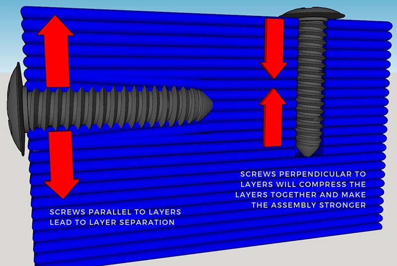
Figure 3. Horizontal and vertical screw diagram showing the layers splitting at the horizontal screw.
SketchUp doesn’t allow you to jump around in the history of all the design moves you made, so going back to make major changes can require a lot of rework. It can also give small but annoying dimensional errors when designing at sub-millimeter scales (https://www.sketchup.com and https://www.autodesk.com/products/fusion-360/overview). Both are staples of the 3D printing world and both have been used for thousands of successful designs.
When you design, avoid the weaknesses and emphasize the strengths of printed parts. Whenever possible, align fasteners to compress the layers rather than split them for best strength.
Make composites with other materials when possible to get the desired combinations of different properties. Slamhound leverages a composite design in the following way: We used 3D printed PETG for a lightweight overall shell and flexible impact handling. We combined that with a polycarbonate “backbone” attached to the print with servo screws for a rigid and tough weapon mount, compression of the printed body, allowing quick access to internals, and “boxing” the chassis for strength.
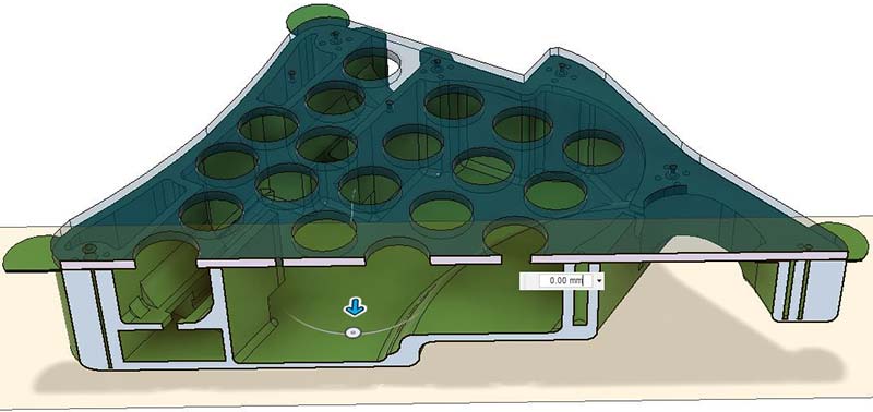
Figure 4. Slamhound Fusion 360 image showing cross section with Lexan.
A powerful design method is to keep weight down by incorporating needed internal reinforcements, penetrations, and armor. Then, you can keep generated infill as light as possible. A little slicer generated infill goes a long way.
We only go solid or use a high number of perimeters if a specific need arises and we seek to avoid that. This weight could go towards your weapon or drive.
An example of this with Slamhound was the use of a fused hole technique to add reinforcement around the printed screw holes. Since we only use one perimeter shell and three or four top and bottom layers, we need some extra plastic to keep the screw holes from breaking when the screw goes in.
Because the extruded filament always contracts a little as it cools, very small vertical holes with sub 1 mm diameters tend to fill in with plastic, becoming solid columns. Figure 5 shows how the tiny holes fill in and become solid reinforcement without excessive slicer infill or perimeters.
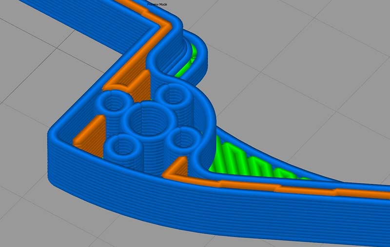
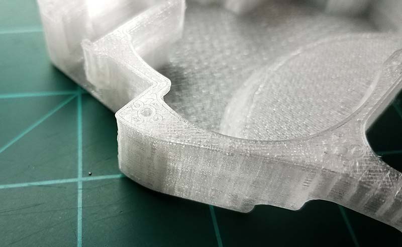
Figure 5. Image from Simplify3D (above) showing hole reinforcement with photo showing actual printed part (below); annotate hole in both sides.
We array the smaller holes around the screw hole to build up plastic in the critical area. We used to use eight microholes but figured out four worked just as well and saved weight. The holes go all the way through the body, so they are anchored to the strong top and bottom layers.
Standard slicer generated infill will not provide much screw holding power. This technique can be extended by adding very thin 0.2 mm slots where you want armor added. The perimeters will fuse together and bridge the gap when printed, and give you two extra “walls” inside your outer perimeter wall or wherever you need more plastic. Also consider how to select and orient your slicer generated infill; look at where the hits will come from and put your infill in compression whenever possible. All slicers will allow you to select the angle that your infill is placed at and most will show you a preview.
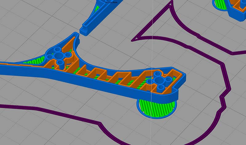
Figure 6. Slamhound infill oriented to protect arms; annotate infill.
Be sure to leverage 3D CAD design to bring in fillets, complex curves, and achieve more strength than sharp rectilinear angles yield. Think of arches in buildings and remember curves can be stronger than straight lines. Get out of the sheet metal and milling design “box.”
For easy reparability, design the inside surfaces to cradle and restrain components. Avoid running wiring through holes in your chassis that would need to be disconnected to work on them. We left a slot for our power switch wire just for this reason. All the motors, ESC (electronic speed controller), battery, switch, and harness can be removed intact as soon as the polycarbonate lid is unscrewed.
When printing, try to run at the hot end of the temperature range that your filament is rated at for best layer adhesion. Don’t be afraid to push a little past the manufacturer’s recommendations, within reason. I run test prints to see what the hottest temperature that works is.
Also, keep the layer height as tall as possible, up to about half of the nozzle diameter, and use the largest diameter nozzle you have available. In simple terms, the more solid plastic and less fused connections you have, the stronger your part will be.
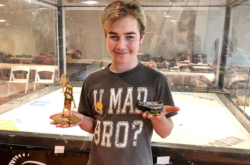
Figure 7. Slamhound driver, Owen Kanoy (age 13) with his 1st place trophy at Clash of the Bots.
Designing parts optimized for 3D printing is a huge topic. We’ve just skimmed over the ocean of potential methods to optimize your robot prints. In future articles, we can further develop many winning ideas — using 3D printed templates for fabricating other materials like our polycarbonate armor, designing for ablation, annealing techniques, and body within body reinforcement are just a few topics for a deeper dive.
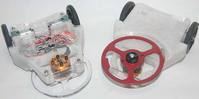
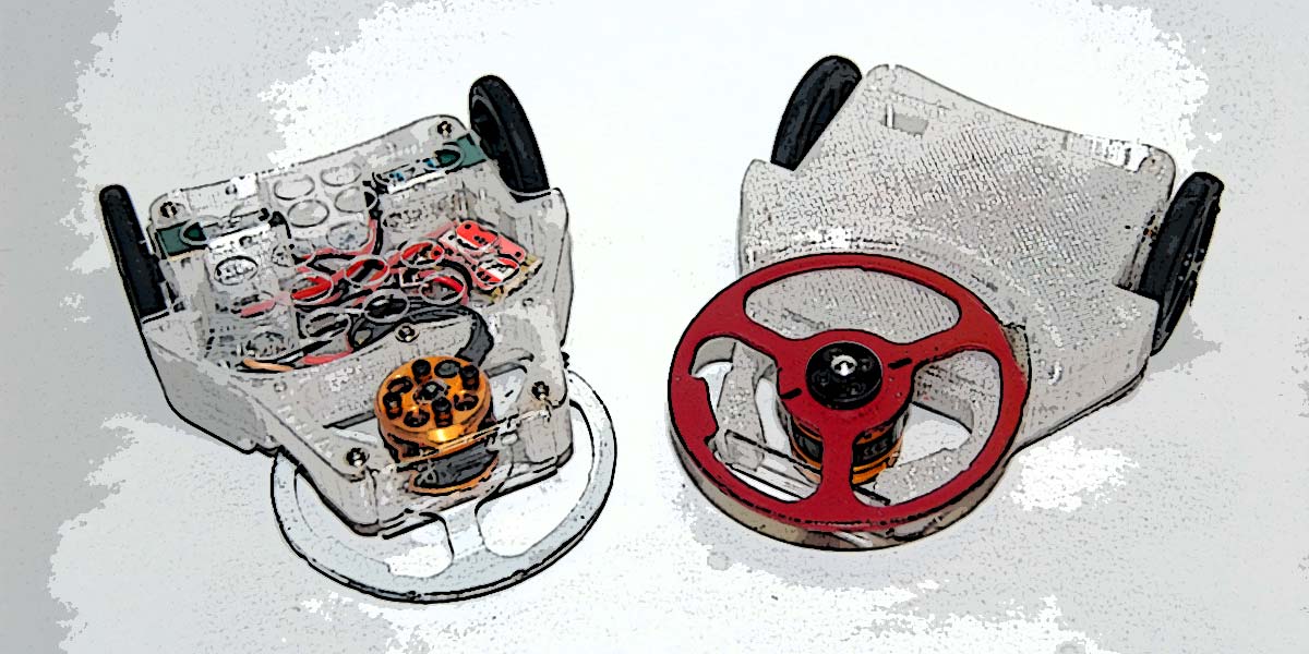
Figure 8. Slamhound, top and bottom.
Always be prepared by carefully reviewing the rules of your competition with regard to materials allowed. Experiment! A big advantage of FDM over that sweet titanium and S7 steel is that the raw material is very cheap, and the designs are easily changed. Make prints, bring lots of spares, and do multiple design iterations you can test to destruction. SV
Article Comments