Deluxe Servo Tester
By Jürgen G. Schmidt View In Digital Edition
Many of us who read SERVO Magazine and Nuts & Volts (www.nutsvolts.com) have worked with hobby servos of one sort or another. Originally, they were controlled with joysticks and trim tabs on radio control (RC) transmitters, but now we frequently control them with microprocessors. Knowing the correct timing signal to send to get the servo to a specific position is frequently a trial-and-error exercise since not all servos are identical. This article will help you build a device which tests and positions servos, giving you the specific timing needed for your programs.
The Background
Hobby servos and other devices — such as the linear actuators from Firgelli — require a specific signal to position them exactly where you want. Frequently, this signal is generated by a program in a microprocessor, and determining the parameters for the program to achieve a desired position can be a challenge. This is compounded by variations between servos.
In the past, I solved this by trial-and-error coding until I had the correct parameters. When I recently had to replace a broken servo and discovered that the original parameters wouldn’t work for the replacement, I decided to build something that would reduce — if not totally eliminate — the trial and error needed to install the new servo.
Those of you who have designed systems with servos will recall that the ideal servo uses a control signal with a period of 20 milliseconds (ms). The typical servo has a control arm that can move either 45 degrees or 90 degrees left and right from a center position. A high signal of 1.5 ms every 20 ms centers the control arm of the servo. A high signal of 1 ms positions it to one extreme; for example, left or counter-clockwise. A high signal of 2 ms will position it to the opposite extreme. Take a look at Figure 1 for an illustration of this.
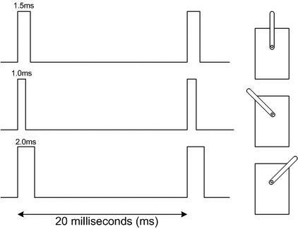
FIGURE 1. Servo signal.
Rarely does real life match the ideal, which is why RC transmitters have trim tabs to account for construction and servo variations. I’ve discovered that many servos advertised as having a 90 degree range of motion can move much farther when the parameters are set outside of the “ideal” range. For example, one 90 degree labeled servo I have moves 45 degrees left and right from center for control signals of 1 ms and 2 ms as expected. However, it swings left from center almost 90 degrees when I send a 0.6 ms control signal, and swings right from center almost 90 degrees when I send a 2.4 ms control signal.
I’ve seen servo testers advertised in hobbyist magazines, and a search on the Internet will reveal circuit diagrams and instructions for making one. These are great for testing the servo and checking on the range of motion. Unfortunately, I haven’t seen one that will tell me the actual width or duration of the control signal I need to program into my processor. It’s time to clear some space on the workbench and make something!
Component Selection and Hardware Design
After leaning back and contemplating the pattern of my textured ceiling for a while, I settled on the following design goals for what I’m calling the Deluxe Servo Tester. These include:
- Multiple buttons or inputs for controlling the servo position.
- Display of the current timing parameter.
- Battery power.
- Convenient for bench and field use.
As I was laying out this project and collecting components to build the breadboard version, I kept adding switches and changing the information I wanted to display. From past experience, I also knew that once I had it built and was using it, I would undoubtedly want to make more changes to the inputs and display. This would result in rewiring, drilling additional holes in my enclosure, and possibly running out of pins on the selected processor.
To avoid this, I decided to use one of the intelligent touch screen displays from 4D Systems. This would get me a lot of design flexibility and a professional look. These displays have been described in past articles in Nuts & Volts (for example, in Thomas Kibalo’s article in the April 2012 issue) and also here in SERVO in previous Mr. Roboto columns.
While these intelligent displays may cost more than a handful of switches and LCD display screens, they can save a lot of time — especially when you (or your customer) haven’t settled on a design for the user interface. The intelligent display only requires a serial port (two pins) from the processor, and adding a button is only a software change. No new wiring is needed for it, nor do you have to drill any extra holes in your enclosure.
The display and servos I would be testing require five volts to operate, so for the battery power I decided to use two 18650 lithium-ion cells. I use these in my LED flashlights, and a pair of cells with a charger costs less than $10 — as long as you’re willing to wait for delivery from China.
I found a low drop-out linear voltage regulator (part BA05CC0T) that delivers five volts from the minimum charge level of the batteries. This part does require at least a 1 µF bypass capacitor on the output side for it to work properly. As you’ll see shortly, this value was increased significantly after testing.
Other components for the Deluxe Servo Tester include a Microchip PIC16F1825 14-pin processor, various connectors, and a 3D printed case. (Check out the Parts List with the sources.)
| DESCRIPTION | PART #/SOURCE |
| 4D Systems 24PTU Display Kit | 971-SK-24PTU |
| PIC16F1825 Processor | 579-PIC16F1825-I/P |
| Positive battery contact (2) | 789-ACC-AAPOS-5223 |
| Negative battery contact (2) | 789-ACC-AANEG-5201 |
| 5 volt LDO Regulator | 755-BA05CC0T |
| Prototyping Board | Adafruit #1609 www.adafruit.com |
| 18650 Battery (2) & charger | eBay |
| Slide switch and other parts | Parts on hand |
| Linear actuators | www.firgelli.com |
| CCS PIC C Compiler | www.ccsinfo.com |
| 4D Systems documentation and software | www.4dsystems.com.au |
| Author’s 3D printer information | www.instructables.com/id/Migbot-I3-3D-Printer-Assembly-and-Use |
| Author website | www.jgscraft.com |
PARTS LIST.
Figure 2 shows the 4D Systems display kit I used.
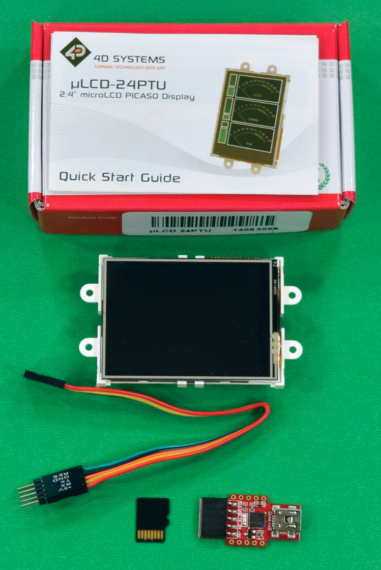
FIGURE 2. Display kit.
This has a 2.4 inch diagonal display area. While this may seem small at first, you’d be surprised how many controls and messages you can squeeze into that amount of space. There are multiple versions for each 4D Systems display, ranging from bare-bones kits which have just the display, to special kits for interfacing with Arduino or Raspberry Pi systems. I usually get the developer kit which includes a cable, microSD card, and programming adapter in addition to the display.
Overall, the circuit is quite simple. The display is connected to the processor serial port, and a single I/O pin from the processor sends the control signal to the servo. Additional processor pins are used to check the battery voltage, provide debugging information, and light the heartbeat LED. The circuit is shown in Figure 3.
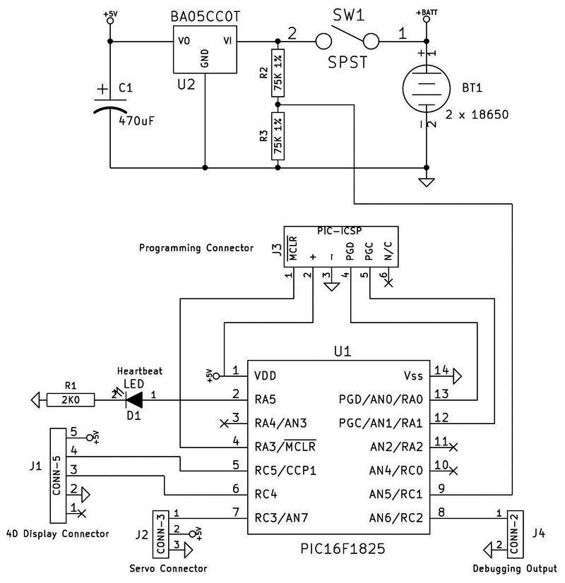
FIGURE 3. DST circuit.
Ideally, any system that uses lithium-ion batteries should have some protection against over-discharge. Some batteries have built-in protection, but I’m not sure the ones I have include that. To address this, I added a voltage display on the screen.
The PIC processor accepts an analog input and can convert a voltage between zero and five volts to a number between 0 and 1023. The combined operating voltage of the two batteries ranges between 8.8V and 5.5V. To measure this with the PIC, I use a voltage divider consisting of two 75K 1% resistors (shown in Figure 3).
If the combined battery voltage is for example, 7.75V, this gets presented to the analog-to-digital converter (ADC) as approximately 3.84V. The ADC, in turn, returns a value of approximately 787 which is — again approximately — 100 times the battery voltage. I reformat this number by inserting a decimal point and sending the result to the display.
I keep saying “approximately” because of accumulated inaccuracies from the actual reference voltage, the voltage divider, and the rounding of 1024 to 1000. Since I’m just interested in a low battery warning rather than a precise voltage measurement, this is good enough. If the measured voltage is below 6V, I display it in red instead of green, which provides a warning that it’s time to charge the batteries.
I recently built my own 3D printer which I used to produce a custom enclosure for this project. The bottom cover slides on, so no screws are needed for fastening it. I finished the printer just a few months before I started this project, so this was my first custom enclosure.
Creating custom enclosures was one of the main reasons for getting the 3D printer, and I was pleased to see that it worked out. The partially assembled results are shown in Figure 4.
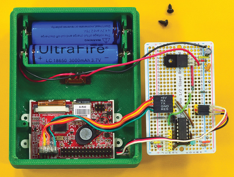
FIGURE 4. Assembly.
The STL files for printing the case are included in the project files at the article link. This was printed using a 0.4 mm nozzle, with 0.2 mm layers and 40% infill. Total print time for top and bottom was six and a half hours.
Software
The heavy lifting for this project is done in software. The user interface is handled by the intelligent display, and the application logic is handled by the PIC processor. 4D Systems provides a free integrated development environment (IDE) called Workshop 4, which I’ll just refer to as the 4D IDE.
You have the option of using one of four development tools which vary in flexibility and ease of use. I chose to use the easiest one — Visi-Genie — since it met my needs, and would get me up and running the fastest. With this tool, you design the user interface by dragging various prebuilt objects such as switches, gauges, and text displays onto a template that matches the size and orientation of your physical display. Once the design is complete, you can test it with the 4D IDE.
The 4D IDE test tools display the hexadecimal data signals that come from the screen when you operate the controls. You can emulate sending instructions from the processor by entering the corresponding hexadecimal sequences. As you go through this testing process, you can make note of the data sent each direction and include that in your application logic.
4D Systems has a number of detailed tutorials and demo projects to help new users get started. The current user interface design for the Deluxe Servo Tester is shown in Figure 5.
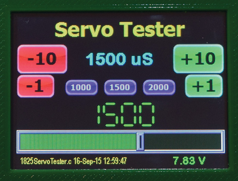
FIGURE 5. UI design.
The buttons are all large enough to be activated individually by my fingers. However, I’ve found that using an old Palm Pilot stylus works better, and keeps the display smudge-free. The display hardware includes a small speaker which I enlist to provide user feedback by playing a “click” sound whenever a button is pressed. The application software that runs on the PIC consists of a loop that:
- Checks for a message from the display.
- Translates this message into a new servo parameter.
- Updates the servo signal.
- Periodically checks the battery level.
- Sends data to the display.
- Starts over.
The 4D IDE project files and the CCS C source files are included in the project files. If you are more comfortable with Arduino rather than PIC systems, 4D Systems has libraries and tutorials for interfacing their displays to Arduinos. The Arduino IDE also has libraries for controlling servos, so most of the complexity in my code can be handled by the Arduino IDE. The comments in my source code should help you in making the translation.
Construction
The 4D Systems displays require a microSD data card, which stores the display information and any multimedia files such as sound and pictures. The SD card must be removed from the display and connected to your computer whenever you make changes to the interface design.
When you install the display hardware into a case, you need to be sure that you leave room to insert and remove this card. Fortunately, the 4D IDE allows you to rotate the display so you can properly position the memory card slot. Figure 6 shows the mostly bare 3D printed case.
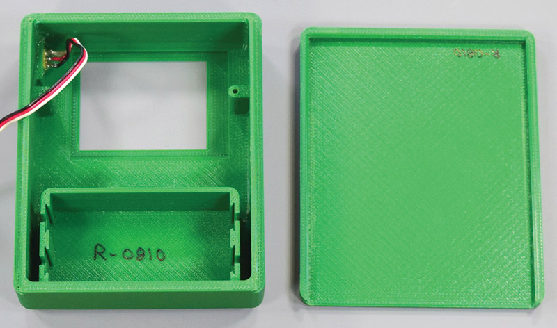
FIGURE 6. Bare printed case.
The sunken rectangle is sized for the display, which will be held in place with a few dabs of rubber cement. The wire is a servo extension cable, the male end of which is carefully glued into the center of an opening in the case.
Figure 7 shows the outside view and the recessed pins that will accommodate standard servo connectors.
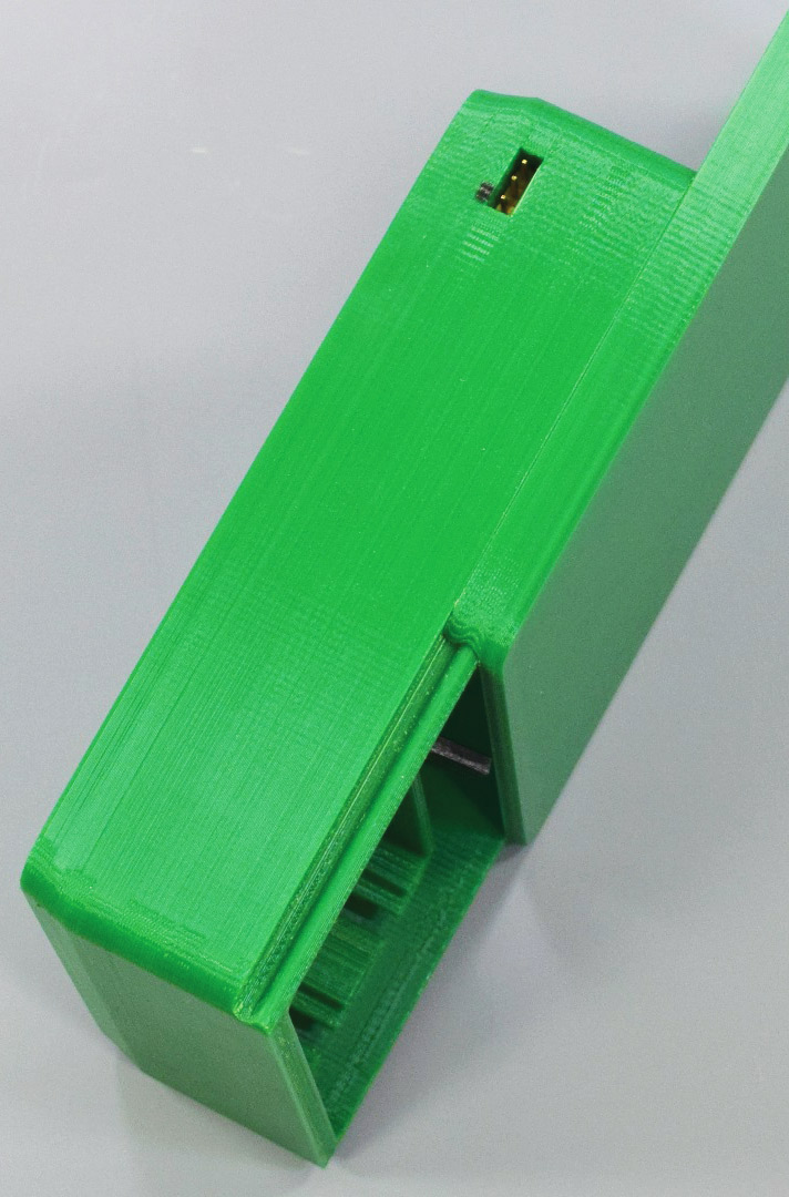
FIGURE 7. Outside of case.
The black mark helps orient the plug for proper polarity. The recessed connector allows me to carry the box around without fear of stabbing myself on the pins or breaking them off as it rattles around in my tool case. In the photo, you can also see the sliding bottom cover.
Referring back to Figure 4, you can see the electronics are mounted on a half-sized prototyping board from Adafruit. I use these boards because it’s easy to copy the circuit from the breadboard. I added right-angle headers for plugging in the display, servo, and programmer. The case has bosses for mounting the board above the display when viewed from the back.
When testing the circuit on a breadboard, I discovered that large movements of my bigger servos would reset the system due to a voltage drop caused by the current drain from the large servo. I solved this by adding a 470 µF capacitor across the power lines on the circuit board to provide a buffer for the power surges.
Hopefully, if you’ve paid attention to articles in this magazine, you know that in a live application — such as a combat robot — you should always separate the logic power supply from the motor or servo power supply.
Operation
Referring to Figure 5, the tester has several inputs. When the tester powers up, the servo output defaults to 1,500 microseconds (µS), so any attached device should be in the middle position. The small blue buttons can be used to test the “ideal” cases of left, center, and right, with signals of 1,000 µS, 1,500 µS, and 2,000 µS, respectively.
The slider across the bottom can be used to test the extremes of your device. This can be used to set the control signal anywhere from 0 to 2,500 microseconds. The number immediately above the slider shows the current slider value, which isn’t actually transmitted to the processor until you lift your finger or the stylus.
The large blue number always shows the value — in microseconds — of the actual control signal currently being sent. The red and green buttons can be used to fine-tune the signal in steps of 1 or 10 microseconds, up or down. This allows you to position the servo or actuator precisely where you want it.
You need to take some care as you explore the full range of the device you are testing. Some servos made unhappy “chattering” noises when I tried to move past their endpoints. A few locked up at the extreme end of the motion and would not return until powered off and then on again.
Once you’ve found the desired position of your device, you can read the blue number from the display and enter that into your servo control program.
In the few months that I’ve been using it, my Deluxe Servo Tester has become one of the tools that makes me wonder how I ever got along without it, and why did I wait so long to make it.
I hope you find it as useful as I do. SV
Downloads
201512-Schmidt.zip
What’s in the zip?
Source code
4D Systems project files for display
3D printer files for the top and bottom portion of the enclosure
Article Comments