
Building a Linear Actuator
By Theron Wierenga View In Digital Edition
While doing some thinking about building a walking bird robot, I researched purchasing linear actuators. What I found is that linear actuators are fairly expensive — especially if you’re an amateur robot builder with a limited budget. This led me to thinking about what it would take to build my own linear actuators.
A linear actuator functions very simply. By powering the DC motor, the arm moves out linearly; by reversing the polarity to the DC motor, the arm moves in. Circular motion is turned into linear motion. A linear actuator is a simple on and off device with no control over the position of the arm. To avoid extending the arm too far in or out, limit switches are often used which must be continually read by a microcontroller.
A servo linear actuator is a more complicated device. However, it does have the ability to position itself. This can be done through the use of servo motors or DC motors that have feedback or encoders attached to them or by sensors to control positioning. My requirements included simple positioning.
The arm needs to move out to position X and then return to position Y, with some speed control. This could be done with limit switches at the needed positions and pulse width modulation (PWM) to control the speed.
Some further thinking and a few sketches later, the idea of using Hall-effect sensors instead of limit switches was added to my plans. A square tube within a square tube was envisioned, to be 3D printed, forming an actuator arm within a body.
At the back end of the inner arm is a captured 1/4 - 20 nut, and just outside the back end of the square body is a captured ball bearing connected to a threaded 1/4 - 20 rod that moves the inner arm by turning in the captured nut.
This ball bearing is 9/32 inches wide with an outer diameter of 3/4 inches and a 1/4 inch inner diameter. The bottom of the inner arm tube has two circular holes at the ends to press-fit 8x3 mm neodymium disk magnets. The bottom of the square body has slots in it to hold small Hall-effect 3144 sensors. Refer to Figure 1.
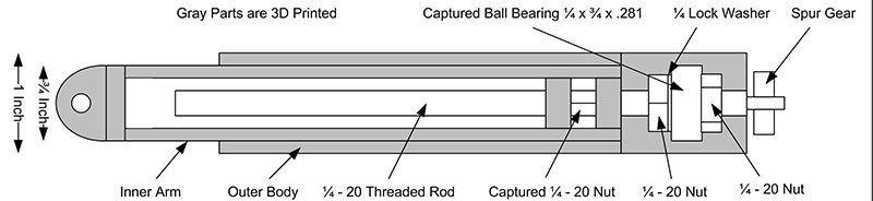
FIGURE 1. Concept diagram, top view.
A single Hall-effect sensor on the bottom (at the forward end of the outer body) can sense the magnets at each end of the inner tube. This then becomes the limit switches but without the mechanical complications of micro switches. If additional specific positioning of the inner arm is desired, additional Hall-effect sensors can be added in the slots.
The complications of this design would be difficult for the amateur builder if it were to be constructed from something like aluminum tubing. Fortunately, 3D printing is a natural for this design and solves a number of construction challenges. Plus, it allows for accurate sizing and alignment. Refer to Figure 2.
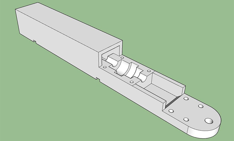
FIGURE 2. 3D model from Sketchup, without the top pillow block to hold the captured ball bearing in place.
Selecting an appropriate DC motor was a challenge, but I was fortunate in my first choice. Electronic Goldmine has a small surplus Johnson brand DC motor (#G9332), reportedly 1-1/16 inches in diameter, 1-1/2 inches long, 6-24 volts, and with a 1/16 inch shaft. The shaft turned out to be .090 inches not .0625.
Because some spur gears are available for 1/8 inch shafts, I increased the shaft diameter by gluing 1/8 inch diameter thin wall brass tubing to the shafts with marine epoxy. This worked quite well and doesn’t appear to have added any vibration. I measured the no-load current of this motor to be about 160 milliamps and the stall current three amps.
For gears, I ordered a number of 48 pitch Traxxas spur gears with 12, 21, 26, and 31 teeth and an 1/8 inch shaft size from Amazon. Some experimenting was done with the Hobbypark 17, 21, 26, and 29 teeth gear set from Amazon. The Traxxas gears run a lot smoother.
There are other sets available with differing numbers of teeth. With different combinations of these gears, one can increase or decrease the speed and torque of the motor. For each pair of gears, the only change in the design is the height of the center line of the motor. Spur gears must be carefully aligned, and any misalignment will cause loss of power, wear, and noise. My goal was to have the linear actuator be able to have a speed of 50 mm/sec. Using the 17-tooth gear on the motor and the 26-tooth gear on the shaft, it averages 84 mm/sec with no load. Having the arm lifting a 550 gram load, it averaged 67 mm/sec. Refer to Figures 3 and 4.
FIGURE 3. Inner arm, top view without top cover.
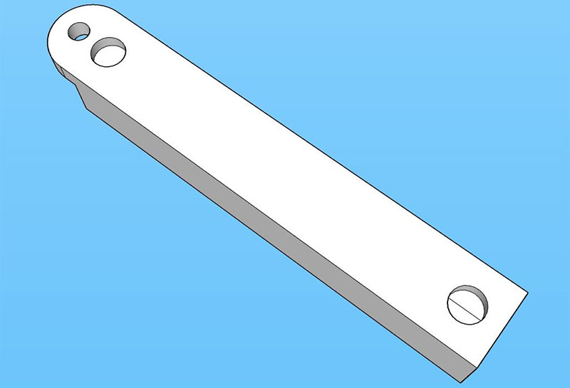
FIGURE 4. Inner arm, bottom view with circular openings for magnets.
Another motor considered was a Tsiny TRS-550PC from www.tsinymotor.com and available on Amazon. This motor is considerably larger at 37-1/2 mm in diameter and 64-1/2 mm long. With a 12 volt power supply, the no-load current is 1.35 amps; nominal current is over 10 amps; and stall current is a whopping 76 amps.
When I clipped leads onto this motor from a 12 volt lead acid battery, I wasn’t holding the motor very tightly in my hand. On start-up, it jumped out of my hand. This would be a good candidate for some heavy lifting.
It will need a hefty motor driver as well; something like the BTS7960. While it’s advertised as a 43 amp driver, this is not a continuous current rating. At 20 amps continuous, this driver will run very hot.
Construction
The majority of time spent on this project was designing the 3D models for the parts and then getting them to print at the exact sizes needed. 3D plastic shrinks on cooling and a 1/4 inch hole ends up being something like 0.243 inches. This will vary depending on the brand of plastic used and even the color in some cases.
PLA was chosen for its ease of use. One can estimate the shrinkage for the various types of plastic, but nothing works better than printing, testing, measuring, and printing again. It’s very important to get all the parts to fit snugly and be well aligned. All the moving parts need to be able to glide smoothly without binding or drag. My models went through many iterations for different designs and sizes. The stroke length on my model is 3-1/2 inches or 88.9 mm. This can be easily lengthened or shortened by changing the length of the inner and outer tubes and the threaded rod. Included in the downloads are all the Sketchup files and their object files for 3D printing. I used Cura 4.6.1 for my slicer.
After 3D printing the inner arm, a 1/4 - 20 stainless steel nut was inserted into the capture space and then the cover screwed down with 1/4 inch 4-40 flat head machine screws. The two magnets are then press-fit into the openings on the bottom. Be sure you have the correct side of the magnet facing out for the Hall-effect sensor.
A 6-1/4 inch piece of 1/4 -20 threaded rod was cut and the end turned down to 1/8 inch to accommodate the spur gear. Double-check the length of the threaded rod because if it’s too long, it can hit the end of the inner tube before the Hall-effect sensor reacts to the magnet. A small lathe is necessary to get good alignment. Care must be taken not to crush the threads of the threaded rod with the lathe chuck jaws.
The threaded rod gets a 1/4 - 20 nut, a 3/4 inch diameter ball bearing, a 1/4 inch lock washer, and a final 1/4 - 20 nut. I used stainless steel for the nuts and lock washer. This assembly is then placed into the capture area at the back end of the outer tube. It’s held in place with a 3D printed pillow block that is held down with four 4-40 flat head machine screws 5/8 inches long. With the chosen gear placed on the end of the 1/8 inch axle coming out of the threaded rod, the assembly should turn easily with very little friction. Refer to Figures 5 and 6.
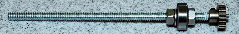
FIGURE 5. Threaded rod assembly.
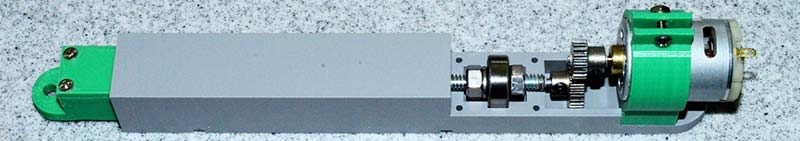
FIGURE 6. Model with separate motor mounts before installation of the pillow block over the ball bearing.
There is an inherent problem here with alignment. While the ball bearing inner diameter is close to 0.25 inches, the threaded rod is not; it’s something like 0.232 inches. When the two 1/4 -20 nuts are tightened down, the threaded rod will not be aligned with the center line of the bearing opening, causing vibration.
To improve this, I coated the portion of the threaded rod that goes inside the bearing with marine epoxy. This blob of epoxy was then turned down on a lathe to 0.25 inches to fit snugly in the bearing. This aligns the threaded rod better with the bearing. Several different models were built; some with an attached motor mount and others with separate motor mounts. A separate motor mount allows for only changing the motor mount when different size gears are used. The gears were left exposed, but additional walls could be added to enclose them. It would also be fairly easy to upscale this design with larger tubes, thicker walls, and a more powerful motor.
A model with the motor directly attached to the threaded rod is shown in Figure 7.
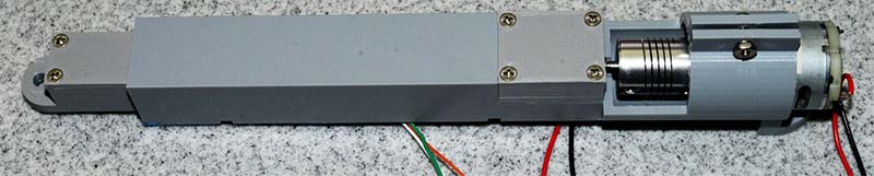
FIGURE 7. A direct drive model, with the pillow block in place over the bearing.
The shaft coupling used is a 3 mm to 3 mm flexible coupling 25 mm in length and 18 mm diameter (found on Amazon). The 3 mm holes were drilled out to accommodate the 1/8 inch shafts. This diameter is only about 0.007 inches larger.
This version performed better than expected. Using the same G9332 motor, the no-load speed was 93 mm/sec and with the 550 gram load 77 mm/sec. The use of geared drives allows for more torque when gearing down, and therefore high lifting power. With a direct drive, one does not have that option. With the use of PWM to a direct drive or spur geared motor, the speed can only be reduced and with a loss of torque. Refer to Figure 8.
| Direct Drive | Spur, Geared Down | Spur, Geared Up | |
|---|---|---|---|
| Torque (Lifting Power) | Fixed | Higher | Lower |
| Speed | Fixed | Slower | Faster |
| Noise | Lower | Higher | Higher |
FIGURE 8. Drive type variables at full power.
Spur gears are known for their noise and a direct drive improves this. Helical gears would be another option, although I had difficulty finding small ones in the sizes I wanted.
Motor Driver and Hardware
An L298N motor driver (Figure 9) was used to power the motor.
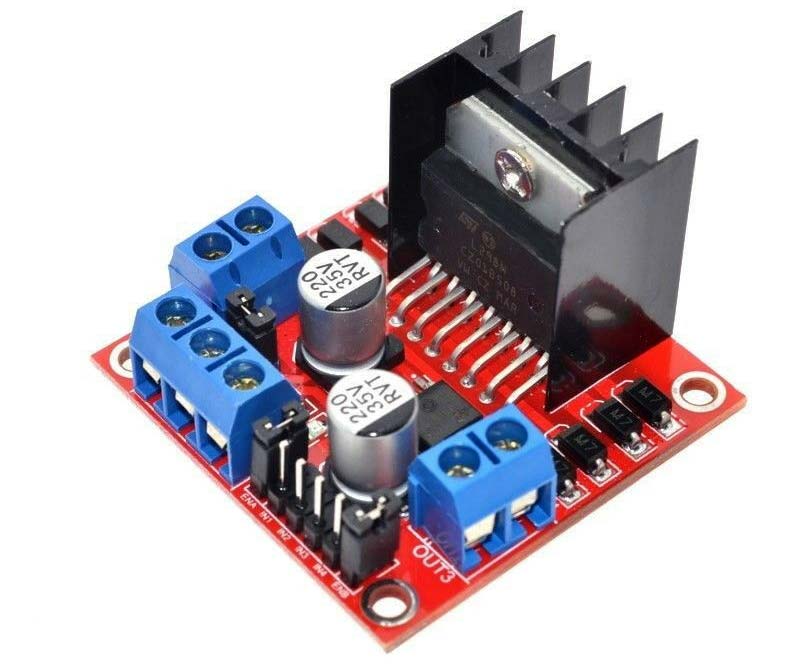
FIGURE 9. L298N motor driver module.
These are widely available and inexpensive. Two DC motors can be driven from one of these modules and it can handle 25 watts or about two amps using a 12 volt battery for power. These modules can be digitally programmed to run a DC motor forwards or backwards, and can also use PWM to vary the speed of the motor.
A simple circuit to drive a single DC motor with feedback from a Hall-effect sensor is shown in Figure 10.
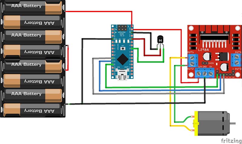
FIGURE 10. A circuit to operate a single motor with the L298N driver and Hall-effect sensors for feedback.
Pin D9 on the Arduino Nano is connected to ENA on the driver board, D8 to IN1, and D7 to IN2. The Hall-effect sensor output is connected to A5, which is used as a digital input pin. Note that the jumpers must be removed on the Enable pins ENA and ENB of the L298N module to use PWM. These jumpers are shown in place on the Fritzing diagram in Figure 10. Although an Arduino Nano was chosen for the microcontroller, just about any other microcontroller could be used.
A printed circuit board (PCB) was designed to fit an ExpressPCB standard MiniBoard at 3.8 x 2.5 inches. This circuit uses a single Nano to drive two of the L298N driver boards (mounted vertically) and headers for eight 3144 Hall-effect sensors. The layout for this board can be found in the downloads. All the pins on the Nano are used, except for D0 and D1 which are used for the serial monitor.
The schematic for the linear actuator drive board is shown in Figure 11.
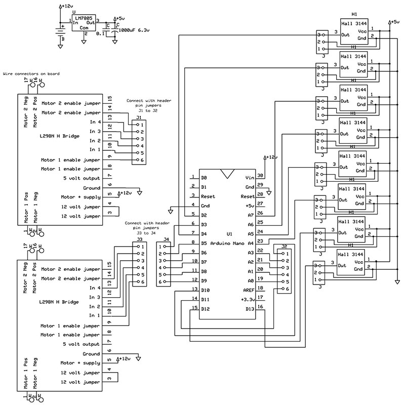
FIGURE 11. Design of linear actuator drive board.
Software
A program for multiple linear actuators to run on the Nano was created and designed for use with the circuit built on the PCB. The program has a few simple functions to control four linear actuators.
The functions available are:
// Retract the actuator arm until it hits the home position
void homeMotor(int motor, int hall, int pwm)
// Soft start by increasing PWM before full power
bool softStartPWM(int motor, int setting, int maxPWM)
// Turn motor on, off, brake or free, turning at full power
bool setMotor(int motor, int setting)
// Turn motor on, off, brake or free turning using PWM
bool setMotorPWM(int motor, int setting, int pwm)
// Read the output of a Hall Effect sensor, a low read means contact
int readHall(int num)
// Run the motor for ¼ second so travel can be measured
void speedCheck()
The homeMotor() function is shown below and is straightforward. It first checks if a correct motor has been defined and if not, it returns with a false. Next, it turns the motor on pulling the inner tube inwards, then begins reading the Hall-effect sensor until it turns on. It then brakes the motor and returns a true:
// Return motor to home positon, which is fully retracted
bool homeMotor(int motor, int hall, int pwm)
{
if ((motor != MOTOR_A) && (motor != MOTOR_B) && (motor != MOTOR_C) && (motor != MOTOR_D)) return false;
setMotorPWM(motor, MOTOR_IN, pwm);
while (readHall(hall) == HALL_OFF) {};
setMotor(motor, MOTOR_BRAKED);
return true;
}
The setMotor() function is quite basic and is only lengthy because it can service four motors. After doing an error check for correct input, it uses a switch statement to select which motor, then another switch statement to select the setting:
// This function is used to turn a motor ON, OFF, BRAKED or OFF (free turning) at full power
bool setMotor(int motor, int setting)
{
if ((motor != MOTOR_A) && (motor != MOTOR_B) && (motor != MOTOR_C) && (motor != MOTOR_D)) return false;
if ((setting != MOTOR_OFF) && (setting != MOTOR_BRAKED) && (setting != MOTOR_IN) && (setting != MOTOR_OUT)) return false;
switch (motor)
{
case MOTOR_A:switch (setting)
{
case MOTOR_OFF: digitalWrite(ENABLE_A, LOW);
break;
case MOTOR_BRAKED: digitalWrite(IN_A1, LOW);
digitalWrite(IN_A2, LOW);
digitalWrite(ENABLE_A, HIGH);
break;
case MOTOR_IN: digitalWrite(IN_A1, LOW);
digitalWrite(IN_A2, HIGH);
digitalWrite(ENABLE_A, HIGH);
break;
case MOTOR_OUT: digitalWrite(IN_A1, HIGH);
digitalWrite(IN_A2, LOW);
digitalWrite(ENABLE_A, HIGH);
break;
}
break;
case MOTOR_B:switch (setting)
{
case MOTOR_OFF: digitalWrite(ENABLE_B, LOW);
break;
case MOTOR_BRAKED: digitalWrite(IN_B1, LOW);
digitalWrite(IN_B2, LOW);
digitalWrite(ENABLE_B, HIGH);
break;
case MOTOR_IN: digitalWrite(IN_B1, LOW);
digitalWrite(IN_B2, HIGH);
digitalWrite(ENABLE_B, HIGH);
break;
case MOTOR_OUT: digitalWrite(IN_B1, HIGH);
digitalWrite(IN_B2, LOW);
digitalWrite(ENABLE_B, HIGH);
break;
}
break;
case MOTOR_C:switch (setting)
{
case MOTOR_OFF: digitalWrite(ENABLE_C, LOW);
break;
case MOTOR_BRAKED: digitalWrite(IN_C1, LOW);
digitalWrite(IN_C2, LOW);
digitalWrite(ENABLE_C, HIGH);
break;
case MOTOR_IN: digitalWrite(IN_C1, LOW);
digitalWrite(IN_C2, HIGH);
digitalWrite(ENABLE_C, HIGH);
break;
case MOTOR_OUT: digitalWrite(IN_C1, HIGH);
digitalWrite(IN_C2, LOW);
digitalWrite(ENABLE_C, HIGH);
break;
}
break;
case MOTOR_D:switch (setting)
{
case MOTOR_OFF: digitalWrite(ENABLE_D, LOW);
break;
case MOTOR_BRAKED: digitalWrite(IN_D1, LOW);
digitalWrite(IN_D2, LOW);
digitalWrite(ENABLE_D, HIGH);
break;
case MOTOR_IN: digitalWrite(IN_D1, LOW);
digitalWrite(IN_D2, HIGH);
digitalWrite(ENABLE_D, HIGH);
break;
case MOTOR_OUT: digitalWrite(IN_D1, HIGH);
digitalWrite(IN_D2, LOW);
digitalWrite(ENABLE_D, HIGH);
break;
}
break;
}
return true;
}
This program doesn’t need to be run with the included PCB design. Point-to-point wiring can be used between the Nano, Hall-effect sensor, driver board, and motor. By following the pin assignments in the program shown below, it can be used as a general interface for one to four linear actuators.
Pin assignments can also be changed in the program to suit user needs.
#define HALL1 A5
#define HALL2 A4
#define HALL3 2
#define HALL4 4
#define HALL5 12
#define HALL6 13
#define HALL7 A7
#define HALL8 A6
#define ENABLE_A 9
#define IN_A1 8
#define IN_A2 7
#define ENABLE_B 3
#define IN_B1 6
#define IN_B2 5
#define ENABLE_C 11
#define IN_C1 A0
#define IN_C2 A1
#define ENABLE_D 10
#define IN_D1 A2
#define IN_D2 A3
A copy of this program is included in the downloads.
Conclusion
This was an enjoyable project, even though many hours were spent getting things “just right.” For the builder, it’s imperative that everything runs smoothly with little friction. It’s worth the extra effort to reprint something (like the inner tube) if it sticks slightly when moving in and out. With the small motor used, it doesn’t take much friction to bind and stall the motor.
When the threaded rod and its bearing are inserted into the main body, be sure everything can turn easily using a thumb on the gears or coupling. A small amount of white lithium grease can be used on the gears and threaded rod to reduce friction. The pillow block that holds the bearing in place should fit snugly, but do not overtighten it.
Using 3D printing allows for custom attachment methods, depending on the use intended for the linear actuator. My models simply have a mounting hole at each end, but a simple redesign would allow a better integration into the model the linear actuator moves. SV
Parts List
| ITEM | SOURCE |
|---|---|
| 1/4-20 Threaded Rod | Home Depot or Lowes |
| 1/4-20 Nuts and Lock Washers, Stainless Steel | Home Depot or Lowes |
| 4-40 Flat Head Machine Screws and Nuts, 1/4, 3/8, and 5/8 lengths | Home Depot or Lowes |
| 4-40 Pan Head Machine Screws 1/2 inch, All Screws and Nuts Stainless Steel | |
| 48 Pitch Spur Gears Traxxas 2412, 2421, 2426, 2428, and 2431 | Amazon or Local Hobby Shop |
| Hobbypark 48 Pitch Gear Set, 17, 21, 26, and 29 Teeth | Amazon |
| Xnrtop 3 mm to 3 mm Shaft Coupling 25 mm length, 18 m diameter | Amazon |
| 8 x 3 mm Neodymium Disk Magnets | Home Depot, Lowes, or Amazon |
| Loctite Marine Epoxy | Amazon or Menards |
| White Lithium Grease | Home Depot or Lowes |
| Johnson DC Motor, #G9332 | Electronic Goldmine |
| L298N Motor Driver Board | eBay or Amazon |
| Battery or Power Supply, 12 volt/3 amp | Home Depot or Lowes |
| Arduino Nano | eBay or Amazon |
| Hall-effect 3144 Sensors | eBay |
| Printed Circuit Board or Breadboard | ExpressPCB |
| Header Pins and Header Jumpers | eBay or Amazon |
| Hookup Wire, Solder | Home Depot or Lowes |
| Ball Bearing, 3/4 inch OD, 1/4 inch ID, 9/32 wide | Amazon |
| If Printed Circuit Board is Built: | |
| LM7805 Voltage Regulator | eBay or Amazon |
| 1,000 µF 6.3 volt Electrolytic Capacitor, .1 µF Capacitor | eBay or Amazon |
| Tools Needed: | |
| Small Lathe | |
| 3D Printer, Plastic Filament, Cuda Software, and Optional 3D Design Software. | |
Article Comments