Building a Bridge to Anywhere
By Bryce Woolley, Evan Woolley View In Digital Edition
We’ve had a longstanding fascination with linear motion in robotics. Maybe it has something to do with the inherent challenge of translating the rotary motion of traditional motors into something different. Maybe it’s the overflowing cornucopia of possible mechanisms achievable with linear motion — everything from the fabulous flippers of BattleBots™ like Bronco and SubZero to boom adjusters on precision agriculture tractors.
This time, we got our hands on the cascading X-Rail kit from ServoCity. We were excited about this kit for the sheer scale and reach of it — a linear actuator with a reach of about 50”! Line up a few of those and you could reach the moon (well, more than a few ... it would actually take over 302 million of them to reach the moon).
We wanted to build something that would take advantage of that long range. In fact, we wanted to build something that would take advantage of the reach of a pair of the cascading X-Rail slide kits.
Taking inspiration from the real historical precedent of bridge launching vehicles, we planned to build a small-scale bridge launcher of our own, capable of spanning a gap of about 50”. Could we take advantage of the full reach of the sliding rails? Would our bridge support the weight of an intrepid crosser? There was only one way to find out.
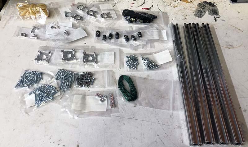
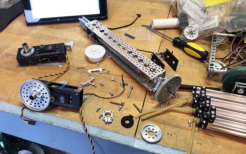
The cascading X-Rail slide kit.
Blast from the Past
Bridge launching vehicles have real historical precedent dating back to World War I and the advent of tank warfare. Armored and tracked tanks could handle a variety of terrain, but could be stymied by the notorious trenches crisscrossing the battlefields of the Great War. If the trench was wider than the length of the tank’s tracks, the armored behemoth could suffer the ignominious fate of face-planting into the trench, tracks spinning helplessly like an overturned turtle.
The simplest solution to this problem was for the vehicle to carry a bundle of something it could use to fill in the trench; something as low tech as a bundle of sticks could provide enough fill so that the vehicle could cross the obstacle. Bridge launching vehicles saw more widespread use in World War II, where tanks and other armored vehicles were ubiquitous. With heavy tanks and other transports advancing across the battlefield together, and some bridges unable to take the weight of the heavy war machines, another solution for crossing terrain was necessary.
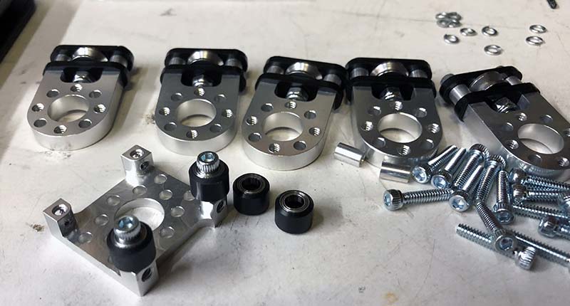
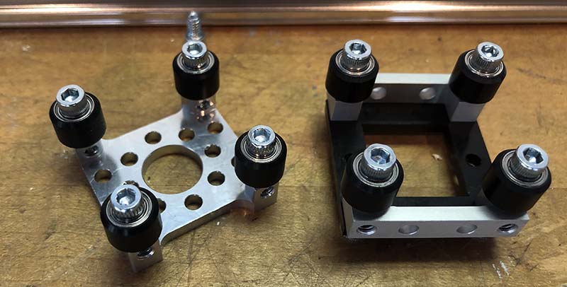
Assembling the sliders and pulleys.
Dedicated bridge launching vehicles were often based on existing tank chassis, with some carrying a two-stage bridge while others were integral to the bridge itself.
Modern bridge launching vehicles can deploy their bridges in a number of ways. Some launchers slide the bridge out linearly on rollers and tracks. Others launch the bridge accordion style, with the whole assembly rotating over a pivot at the outset before the stages separate like an albatross extending its mighty wingspan. Most bridge launchers use two stages, with some variation possible in the stage sizes to achieve different bridge lengths.
Bridge launching is a real engineering problem sometimes solved through linear actuation. Our bridge launcher wouldn’t have to perform under a hail of bullets, but would the cascading X-Rail slide kit be up to the task?
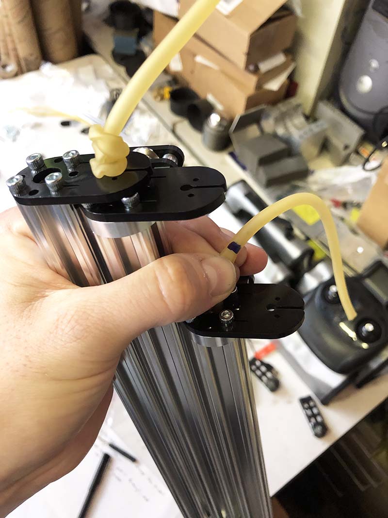
Inserting the tubing.
Riding the X-Rails
Fans of Actobotics (like us) will find a lot of familiarity in the cascading X-Rail slide kit. The kit comes with individually bagged parts, all labeled for easy reference. The machined aluminum parts feature the classic overlapping hole patterns, and the primary fasteners are various lengths of 6-32 screws. As with every Actobotics kit, the instructions for the cascading X-Rail slide kit are online in the form of a well-paced and slickly produced YouTube video.
This video makes more use of 3D animations than a camera watching a human assembler, but the animated steps probably give a better closer-up view of the components than would be possible otherwise. The assembly will — for the most part — feel familiar with Actobotics aficionados. Even for the uninitiated, the instructions are clear and easy to follow.
The video gives a rundown of the parts needed for each step, though at such a quick pace it often sent us fumbling for the pause button as we fished the requisite length of 6-32 screws out of the bag.
The assembly of the cascading rail kit is repetitive in the same comforting sense as the consistent cast of characters in a long-running TV show. The steps go stage by stage, and they are all pretty similar. There are the slide plates made from a shiny machined aluminum piece, some screws, and some rollers. There are the endcaps, made from oblong plastic bits with orientations that become intuitive once you realize how the whole device fits together.
Plotting how to motorize.
The instructional video gives a mix of zoomed-in views, so you can see precisely where the mounting holes on the X-Rails line up with the hole pattern on the endcaps, along with wide perspective views so you can get a sense of how all the stages fit together.
One of the unusual and challenging parts of working with the kit is the soft stuff: the latex surgical tubing and the string used to rig the pulleys. The most distinctive feature of the Actobotics kit is the hole pattern: a regular, predictable pattern where everything lines up and fits together like you’d expect. The soft components are another animal, with the fixed regularity of the hole pattern gone in favor of stretchy unpredictability.
The tubing (at least) is forgiving to work with. The kit comes with one long length of tubing that you need to cut into fourths. The kit only requires three lengths, so it’s comforting to know there’s a spare at the ready.
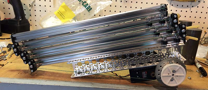
A completed X-Rail slide.
We did diverge a bit from the instructions with how we installed the tubing into the X-Rails. The instructions recommend putting a double knot into one end of the tubing, measuring 10 inches out from that knot, and tying another double knot. The second knot leaves a long strand at the end, which is supposed to assist the builder in snaking the tubing through the hollow center of the X-Rails.
We found, however, that the double knots were too chunky to fit through the hollow center of the X-Rails. So, we tied the first end, marked the second end, and didn’t put in the second knot until the tubing was all the way through the X-Rail, the pulley block, and the endcap.
After working through four stages of assembly, the cascading X-Rail slide is structurally complete and ready to have the pulleys rigged with a long, waxy green string that also comes in an abundant length. The video instructions don’t actually cover the rigging, but the ServoCity website provides an easy-to-follow PDF diagram.
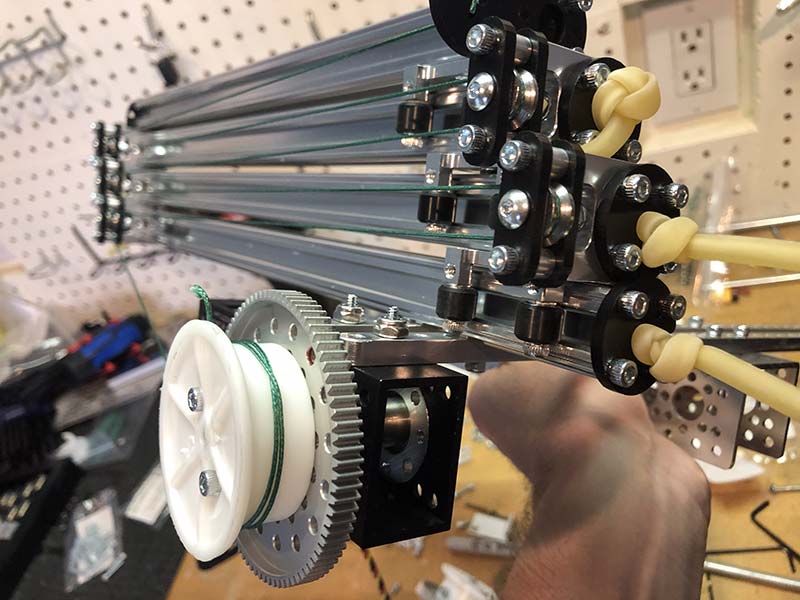
A closer look at the rigging.
The waxy string has a little bit of rigidity to it, so it’s more like stringing an al dente spaghetti noodle through the pulleys rather than the floppy nightmare that a well-cooked noodle would be. It’s actually way easier than using even the most perfectly cooked piece of pasta because the instructions are clear and the string isn’t too fiddly.
With the pulleys rigged up, the X-Rail slide is ready for motorization. Well, almost ready.
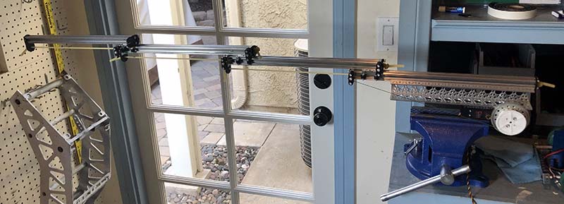
Impressive reach!
Since our bridge design involved two cascading X-Rail slide kits, we had to do the assembly all over again on the second one. It started out faster than before, benefitting from the speed that accompanies experience. Unfortunately, we were soon stymied by an unexpected but all too common problem.
The kit comes with three aluminum plates that form the backbone of the slides that allow the X-Rails to move along each other. We put the first two slide panels together no problem. As we began on the third, disaster struck. We dropped the plate. Or rather, pushed it off the workbench somehow.
In one moment it was chilling in our pile of parts, patiently awaiting assembly, and in the next it was gone. We didn’t even hear it hit the ground and bounce, so we couldn’t even use that sonar sense that many builders have honed over the years by tracking down errant screws that always seem to attempt escape when you’re all out of spares.
Bodging a substitute.
We spent the obligatory time on hands and knees looking for it, but to no avail. It must have bounced into that same alternate dimension where all of the 10 mm sockets go to hide. However, our ordeal simply brings us to one more benefit of the regularity and predictability of the Actobotics system. All the missing plate needed to do was provide support for some slider wheels, and to mount them at the right height in a square pattern.
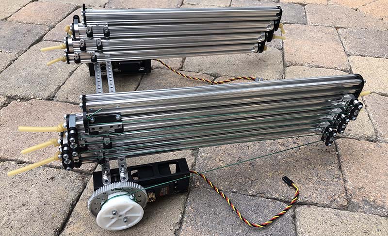
Dual X-Rail slides.
The regular Actobotics hole pattern meant that a piece from another kit had precisely the hole spacing we needed. Two other small aluminum parts gave the wheels the height they needed, and on the whole we thought our bodged-together replacement didn’t look too bad. We were quicker with the tubing and the string this time, and soon we had mirror twin cascading X-Rail slides.
Reach Out and Touch ... Something
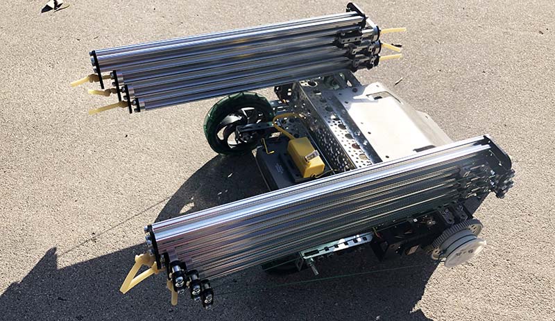
With the X-Rail slides structurally complete, we now had to solve the riddle of motorizing them. The kits themselves do not come with a motor, but the ServoCity website offers a few select pairings, like an expert sommelier hoping to help bring out the best flavors in your entrée with the ideal wine accompaniment. But like the guys that order a Bud Light in spite of the expert recommendations, we decided to go a different route. We opted to use the servo gearboxes from ServoCity that we had used with great success with our can-crushing robot (in the March 2018 issue).
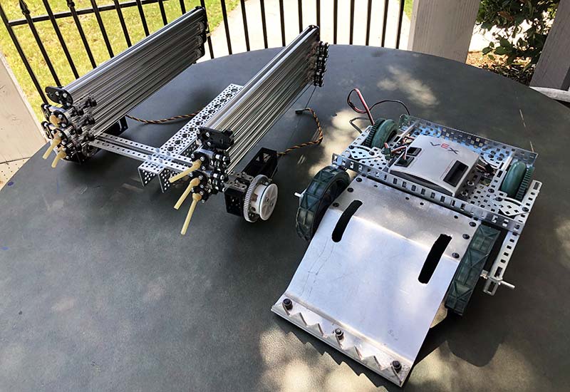
Finding our bot base.
The gearboxes gave the servos great torque that we were confident could fully extend the bridge, and the gearboxes themselves provided some nice structural mounting points for attaching the gearboxes to the bridge and the whole assembly to a driving base. We also favored the servo solution because we already had the answer for power, drive, and control: our trusty VEX kit. The original VEX Robotics Design System is a bit of a dinosaur now, but we keep coming back to it like how Hollywood keeps going back to timeworn franchise material like The Terminator. The VEX controller is an easy way to source the 5V that most servos hunger for, and the six-channel radio is easily programmed. For us, it has been a trustworthy prototyping platform for years.
Before settling on our driving base design, we wanted to test the X-Rail slides to ensure that they worked. Actobotics does offer elegant solutions for the rail locomotion, including specialized pulley wheels that attach to motors with a simple hub. We used a length of channel as a structural piece and fashioned our own spool out of a random plastic hub we had floating around the workshop. It was easy to mark out and drill the hole pattern onto the plastic hub, and adding a screw to the wall of the hub provided an anchor point for the pulley string. We locked the whole assembly into a vice, wired it up to the VEX brain and power, and crossed our fingers that we could reach out and touch something.
Reprogramming the VEX.
The X-Rail slide extended quicker and smoother than we had expected. The servo gearbox was also able to achieve a holding position when we eased off the throttle. The stretch of the tubing — while providing a fair amount of tension — didn’t immediately force the stages to collapse.
When fully extended, the X-Rail slide could reach almost to the wall facing the vice, nearly spanning the doorway. Per the specs on the ServoCity website, the kit is capable of holding a two pound load at the end of the fully extended slide. Given the apparent soundness of our half of a bridge, we thought that number was (if anything) conservative. We guessed that too heavy a load on the end would cause a failure in one of two ways: either the X-Rail would simply pop loose from the slide plate; or the slotted end of the plastic endcaps would come loose. That’s all just conjecture though, because the slides remained unscathed for the duration of our project.
Mind the Gap
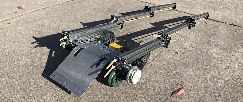
With the functionality of the slides confirmed, we next turned to the driving base. Instead of figuring out a way to Frankenstein the slides onto the top of the existing VEX robot, we opted to disassemble it and start from scratch, like a caterpillar dissolved to goo in the pupa before becoming a beautiful butterfly. We positioned the drive base so that the slides were on the outer edges, giving us a nice wide bridge. Mating the Actobotics and VEX parts together was easy enough — there was plenty of overlap between the hole patterns so that we could pick up a few mounting points.
Ready for a test drive.
We had a bit of an unexpected challenge when it came to mapping the controls. One reason we still use the dinosaur of the original VEX kit is because the control solution is so easy. There’s a nice six-channel radio with a surprising amount of functionality. You can do mixing, and there are preset modes for arcade style (mixed to one stick) and tank style (two sticks) driving.
We wanted our drive mixed on one stick, with the bridge mixed to the other. Sadly, no matter what mode we put the radio on, the radio could only ever either make the bot drive or the bridge extend — not both. We realized that the controller itself had been reprogrammed many moons ago when the VEX kit was being used in the VEX Challenge competition. Could we change it back? We could, but it would take another dinosaur.
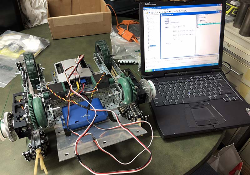
This one was an old laptop, thick and heavy like a slab of concrete. It ran Windows XP and made a variety of mildly alarming noises when first turning it on. Bafflingly it still worked, and we were able to open Easy C to reprogram the VEX bot. Just a few simple changes were all it took, and soon we had the drive working on one stick and the bridge working on the other.
The robot drove surprisingly well with the bridge mechanism on top. The base became unbalanced when we extended the bridge too far, but that could be fixed with some ballast under the entrance ramp at the back of the bot. Our invisible bridge would not be nearly as effective as the one Indiana Jones crossed on his way to the Holy Grail in The Last Crusade, so we still needed to figure out a way to turn our pair of slides into a real causeway.
Extending the slides.
One option would be to put rigid plates at each stage, but that would create a stepped bridge that might be difficult for a small vehicle to cross. We envisioned something flexible, unfurling gracefully as the slides extended. We wanted some kind of fabric, something that could be pulled taut by the extended bridge so that a vehicle could cross safely.
Given the reach of the slides and the fairly wide wheelbase of the robot, we needed a good sized piece of fabric. Knowing that using a perfectly good sheet would be frowned upon, we hunted around Robot Central and found an old pillow case.
The black stains on the yellowed fabric indicated that it was used as a painting mat in a previous life, so we figured being reincarnated into a bridge would be an upgrade.
We marked out the dimensions, making it just shorter than the fully extended length of the bridge to ensure it would be stretched taut. We fastened one end of the bridge to the driving base under the entrance ramp, and we attached the other end to the end caps on the last stage of the slides. We fashioned an exit ramp from a thin sheet of aluminum, and our bridge launcher was ready for testing.
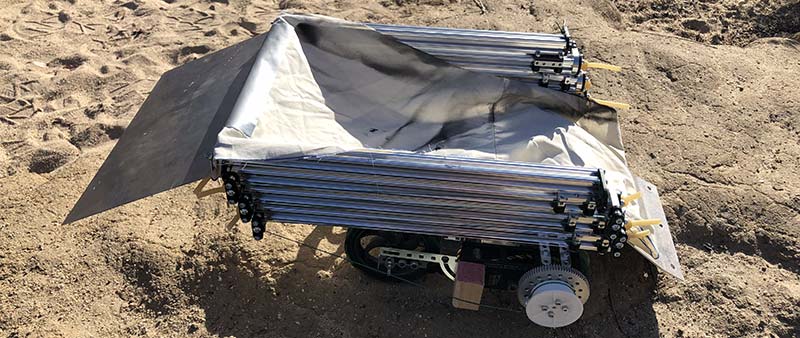
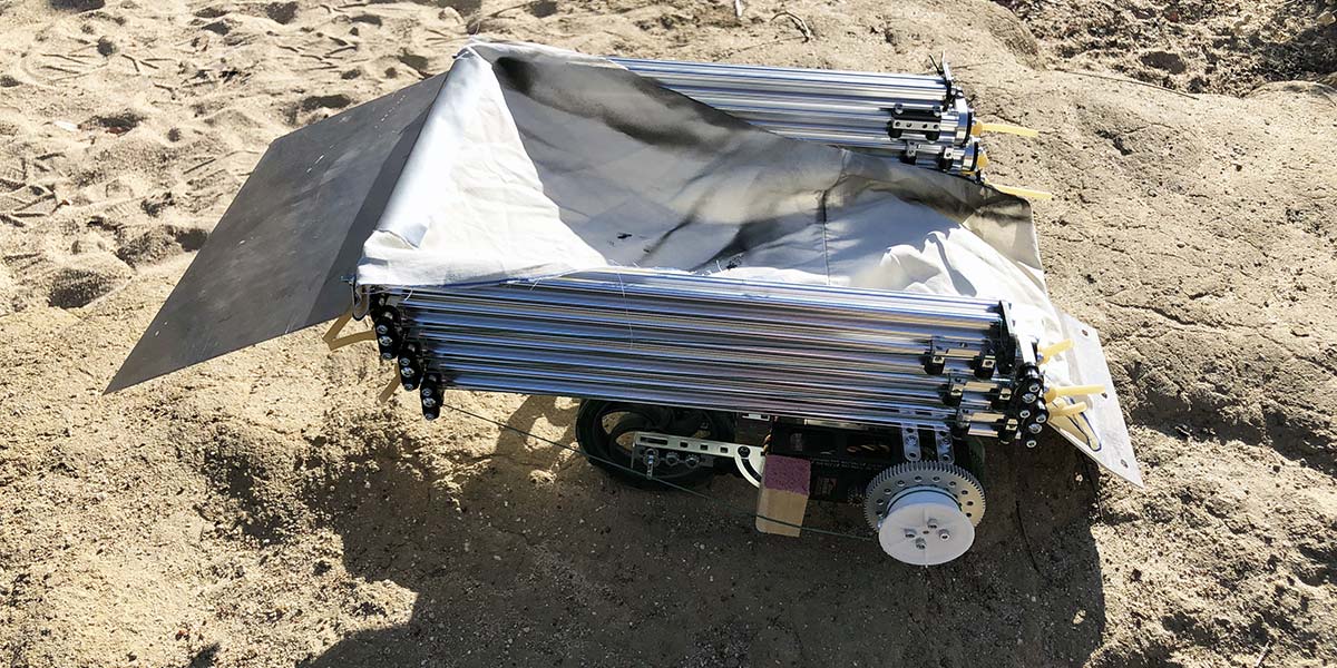
Ready to bridge the gap.
We brought the bot out to the driveway; no crevasses to span there, but still a good place to see whether the bridge extended properly. We hoped the slides would extend in concert. If one slide was quicker than the other, the fabric bridge could hinder further extension. We slowly ramped up the throttle and were delighted to see the slides extend in unison. But would it really work as a bridge? We needed a small vehicle to drive across it to find out, so we scoured Robot Central for small bots and RC cars.
The first complete pairing of bot and remote we found was actually one of the old BattleBots toys; Killerhurtz to be exact. We removed the shell to give the RC car a bit more ground clearance to make it up the entrance ramp. Now all we needed was some treacherous terrain to cross.
Robot Central is only a short walk away from a lovely meadow. It’s a perfect place to ride a bike, run with dogs, and ponder robot design ideas while on a serene nature walk. Part of the landscape is dominated by a dry creek bed, with smaller tributaries having cut crevasses that crisscross the meadow. One of these smaller washes (much less intimidating than a World War I trench) would be an ideal spot to test our bridge launcher.
We found a spot with some reasonably flat and driveable areas on either side of a small crevasse. We positioned the bridge launcher in place and extended the bridge. The long arms of the X-Rail slides spanned the gap easily and pulled our fabric bridge taut. We drove the naked Killerhurtz up the ramp, over the bridge, and to the other side. Any unsuspecting German fortifications would have been doomed.
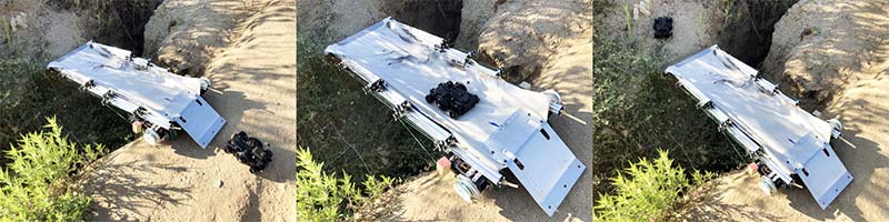
Bridge launching success.
Overall, we were very pleased with the cascading X-Rail slides. The unit has an impressive reach that is long enough to be useful without being too clunky or slow. Other Actobotics kits like the servo gearboxes were a breeze to mate with the slides, and even the dinosaur of a VEX robot proved to be a worthy base.
Even so, we know it’s time for an upgrade for our go-to driving platform. Picking up another Agent 390 tracked base from Actobotics might be in order because that would be an ideal platform for all of the crazy and awesome mechanisms in the Actobotics repertory.
The only thing you need to bridge the gap between the versatility of Actobotics and your next cool robot is your imagination. SV
Article Comments